EP1233092A1 - Zungennadel mit fixierter Feder - Google Patents
Zungennadel mit fixierter Feder Download PDFInfo
- Publication number
- EP1233092A1 EP1233092A1 EP02000417A EP02000417A EP1233092A1 EP 1233092 A1 EP1233092 A1 EP 1233092A1 EP 02000417 A EP02000417 A EP 02000417A EP 02000417 A EP02000417 A EP 02000417A EP 1233092 A1 EP1233092 A1 EP 1233092A1
- Authority
- EP
- European Patent Office
- Prior art keywords
- leaf spring
- tongue
- spring
- needle
- latch
- Prior art date
- Legal status (The legal status is an assumption and is not a legal conclusion. Google has not performed a legal analysis and makes no representation as to the accuracy of the status listed.)
- Granted
Links
- 238000009940 knitting Methods 0.000 claims description 4
- 230000000087 stabilizing effect Effects 0.000 claims 1
- 210000002105 tongue Anatomy 0.000 description 86
- 230000036316 preload Effects 0.000 description 4
- 230000007704 transition Effects 0.000 description 4
- 230000002411 adverse Effects 0.000 description 2
- 230000006735 deficit Effects 0.000 description 2
- 230000000694 effects Effects 0.000 description 2
- 238000004519 manufacturing process Methods 0.000 description 2
- 230000004323 axial length Effects 0.000 description 1
- 238000007664 blowing Methods 0.000 description 1
- 238000004140 cleaning Methods 0.000 description 1
- 238000006073 displacement reaction Methods 0.000 description 1
- 230000009760 functional impairment Effects 0.000 description 1
- 238000011282 treatment Methods 0.000 description 1
Images



Classifications
-
- D—TEXTILES; PAPER
- D04—BRAIDING; LACE-MAKING; KNITTING; TRIMMINGS; NON-WOVEN FABRICS
- D04B—KNITTING
- D04B35/00—Details of, or auxiliary devices incorporated in, knitting machines, not otherwise provided for
- D04B35/02—Knitting tools or instruments not provided for in group D04B15/00 or D04B27/00
- D04B35/04—Latch needles
Definitions
- the invention relates in particular to a latch needle for knitting machines.
- Some knitting machines require latch needles, whose Tongues other than their reserve and your closed position at least have a further pivot position in which the tongue is resilient and not on the hook or the Fit the needle shaft.
- tongue slot pivoted tongue with one in the tongue slot arranged leaf spring in contact.
- the latch needle disclosed here has a bottom side arched tongue slit with a breakthrough leading to the needle back stands.
- the arched leaf spring rests one end of the pivoted tongue that the Tongue storage is immediately adjacent.
- the two Ends of the leaf spring lie on the bottom of the tongue slot and bridge the breakthrough.
- At least one end of the leaf spring is at least in one embodiment with respect to the longitudinal direction of the leaf spring the needle body. This is in the tongue slot a small hole or opening is formed into the one angled end of the leaf spring engages.
- the latch needle according to the invention has one in the Tongue slot arranged elongated leaf spring, the Ends are held at corresponding bearing seats.
- the Bearing seats are on the narrow sides or front sides of the Tongue slot arranged and each have one Contact surface and at least one of the contact surface in the essentially opposite counter surface.
- the Leaf spring end is thus between the contact surface and the counter surface and can therefore not from the Escape camp seat.
- the counter surface can be on one connected to the narrow side of the tongue slot Projection as well as on one or more on the flank of the tongue slot provided projections his.
- the spring end of the leaf spring form-fitting with little play in the bearing seat held.
- the leaf spring can thus both freely some axial movement as well, at least in one sufficient area to perform a swivel movement.
- the Leaf spring installed under tension so that its ends without axial play, under tension, held in the bearing seat are.
- the ends of the leaf spring are at both Possibilities in this respect loose (i.e. swiveling within limits and axially displaceable) clamped. Even so, one will accidental loss of the leaf spring safely locked out. Consequently, the function of the Receiving a latch needle. Errors or functional impairments, otherwise by losing the leaf spring can occur are avoided.
- the spring keeps in despite the securing of its ends the bearing seats their spring characteristics. impairments the spring characteristics as they would appear when the ends of the leaf spring are welded to the bearing seats or otherwise fixed axially immovable would be excluded.
- the latch needle lies in the greater scope for design in determining the shape of the leaf spring and its Spring characteristic.
- the leaf spring can be designed so that they do not end with the end of the Tongue is in contact. This can cause friction between the leaf spring and the tongue are reduced, so that needles with particularly smooth spring-assisted Tongue that can be produced.
- the needle according to the invention is not only regarding different operating conditions, but about it also regarding unforeseen treatments, like blowing out with compressed air, for example for Cleaning the knitting machine, insensitive.
- the leaf springs are due to the special design of the bearing seat held tight so that by the action of the compressed air only slip insignificantly and not out the tongue slot can be blown out.
- the Leaf spring on the bearing seats held so that they are limited axial, i.e. slidable in its longitudinal direction is.
- the axial position of the leaf spring is then for example by a V-shaped or otherwise bent area of the leaf spring set with the bearing end of the tongue is in contact.
- the influence of production tolerances with regard to the precise arrangement of the tongue bearing and the length of the leaf spring on the function of the Tongue needle can be reduced.
- a Impairment or influence on the spring characteristic avoided by clamping effect on or in the bearing seat another embodiment, the ends of the Leaf spring held under tension on the bearing seats.
- the leaf spring is then in axial, d. H. longitudinal not movable. This makes it possible to To influence the preload of the leaf spring. Also at In this embodiment, it is critical that the The ends of the leaf spring are not permanently or firmly fixed are. They are under tension but movable in the Bearing seats.
- the bearing seats are preferably designed that the leaf spring is not clamped to the bearing seats is.
- the leaf spring is movably mounted. This serves also the functional reliability and quality of the Latch needle. The characteristic of the spring characteristic is not affected by the bearing seats.
- the counter surface and the contact surface can be one Form pocket into the relevant end of the leaf spring protrudes. This represents a particularly safe storage of the Leaf spring.
- the latch needle can be designed so that the Leaf spring in one existing between its ends Area is permanently against the tongue and therefore below Preload is there.
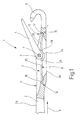
- a tongue needle 1 is illustrated in FIG. 1, which has a needle body 2 with a tongue slot 3.
- a tongue 4 which is with her End 5 extends into the tongue slot 3, pivotally mounted.
- the tongue 4 forms with one end of the needle body 2 trained hook 6 a thread space it opens and closes. Serves to store the tongue 4 a extending across the tongue slot 3 Pin 7.
- the tongue slot 3 extends through the Needle body 2 through. He is in the preferred embodiment both on the needle top 29 and open at the needle back 30.
- a leaf spring 8 is arranged in the tongue slot 3, which is roughly parallel to the longitudinal direction (Arrow 9) of the needle body 2 and / or parallel to the Side cheeks of the tongue slot 3 extends.
- the leaf spring 8 has the task of the tongue 4 to bring out their end positions; e.g. serves the leaf spring 8 to lift the tongue 4 from the hook 6 and into the to transfer position illustrated in Figure 1. This serves to open it up to another tongue Facility, such as a brush to facilitate to come into engagement with the tongue 4.
- the tongue slot 3 has two through the slot cheeks formed long sides and two narrow sides 11, 12 on which bearing seats 14, 15 are formed. This serve to grasp ends 16, 17 of the leaf spring 8, so that the leaf spring 8 in the tongue slot 3 captive is held.
- the bearing seats 14, 15 are approximately mirror images of one another educated.
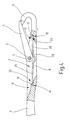
- the bearing seat 14 is shown in FIG. 2 representative of both bearing seats 14, 15 illustrated. The following description of the bearing seat 14 therefore also applies to bearing seat 15.
- the bearing seat 14 has a bearing surface 18, which are aligned essentially parallel to the leaf spring 8 is.
- the contact surface can be a flat surface or be a somewhat domed surface. Your across to the width measured in the longitudinal direction (arrow 9) is somewhat greater than the width of the leaf spring 8.
- the width of the Leaf spring 8 is slightly less than that of the tongue slot 3, so that the leaf spring between the slotted cheeks is mobile.
- the bearing surface 18 is opposite one on the narrow side 11 formed projection 19 a Counter surface 21 formed.
- the projection 19 engages the end 16 of the leaf spring 8 and thus forms with the Bearing surface 18 a pocket 22 whose depth is so great that the end 16 is held securely.
- the leaf spring go through a certain stroke H, which at the ends 16, 17th leads to certain length changes L1, L2.
- the location of the Pockets 22 formed on the bearing seats 14, 15 are arranged (embodiment according to FIG. 3), that the leaf spring 8 when it is its largest Has longitudinal extension, with its ends 16, 17 not at the Bottoms 23 of the pockets 22 abuts.
- the pockets 22 are moreover so deep, i.e. the counter surfaces 21 are like this long that the leaf spring 8 even at maximum deflection or displacement do not fall out of the pockets 22 can.
- the depth of the pocket 22 is at least as great like the axial play of the leaf spring 8 plus the two Length changes L1 and L2.
- the leaf spring 8 has, as is also shown in FIG. 1 one can see in an approximately middle range e.g. Section or area 24 bent in a V-shape, which rests resiliently at the end 5 of the tongue 4. From the V-shaped Section 24 extends two legs 25, 26 of the leaf spring 8 away. A transition 27 of the V-shaped Section 24 to the leg 25 serves the tongue 4 support when it is in reserve. A corresponding one Transition 28 supports, as Figure 1 illustrates Tongue 4 when they are close to their closed position located.
- FIGs. 8 and 9 Another embodiment is in Figs. 8 and 9 shown.
- the bearing seat 15 becomes representative illustrated for both camp seats.
- the following Description of the bearing seat 15 thus also applies to the Bearing seat 14 accordingly.
- the leaf spring 8 is under Bias is held in the bearing seat 15. Thereby lies its end 17 on the bottom 23 of the pockets 22 under Tension. Performs the leaf spring 8 in its Starting position the tongue 4 not or only insignificantly touched, a stroke H in the direction of the needle back, so move due to the resulting Length changes L1, L2 the ends 16, 17 of the leaf spring 8 away from the bottoms 23 of the pockets 22.
- the leaf spring 8 is then free to move.
- the pockets 22 are above out so deep, i.e. the counter surfaces 21 are so long that the leaf spring 8 is not at maximum deflection can fall out of the pockets 22. That is the depth the pocket 22 at least as large as that Length changes L1 and L2.
- the latch needle 1 described in FIGS. 1 to 6 works as follows:
- the leaf spring 8 rests on the tongue 4. Due to the reciprocating movement of the latch needle 1 in the direction of arrow 9, as well as against the direction the same, and possibly by the effect of additional Actuating means, such as brushes or the like, the Tongue 4 constantly moved back and forth. Slides one Loop over the tongue 4, this will briefly like Figure 4 illustrates, pressed against the hook 6.
- the tongue 4 deflects the leaf spring 8 in the direction the needle back 30 by the leaf spring 8th at the transition 28 in the direction of the needle back 30.
- the leaf spring 8 is thereby deformed resiliently. Thereby also pivot the legs 25, 26 somewhat about their respective Bearing seat 14, 15.
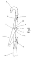
- the illustrated stable position is one in which the transition 27 the Tongue 4 supports and prevents the needle body 2 to rest. By deflecting the leaf spring 8, the Tongue 4 are pressed against the needle body 2. The the tongue 4 transfers resilient action of the leaf spring 8 then back to the illustrated stable position.
- FIG. 6 shows a modified embodiment of the Tongue needle 1 illustrated.
- the latch needle 1 is an elongated in the latch slot 3
- Leaf spring 8 ' without the V-shaped section 24 arranged.
- the leaf spring 8 ' can either completely be straight or slightly curved.
- the tongue 4 at its end 5 has more suitable Place arranged flats 31, 32 on the in the desired stable positions of the tongue 4 flat rest on the leaf spring 8 '.
- the leaf spring 8 ' apply the above statements.
- FIG a latch needle 1 illustrates.
- the camp seat is marked by a the narrow side or end face 11 of the tongue slot 3 formed paragraph set. With this goes Support surface 18 in one step, the pocket bottom 23 can be seen in the remaining course of the narrow-sided Limiting the tongue slot 3 over.
- the tongue slot serves at least one projection 33 which from the Slot flank can be pushed out and at its the Leaf spring 8, 8 'side facing the counter surface 21 having.
- slot flank also such projection 33 may be formed.
- FIG. 8 and 9 is a latch needle 1 illustrated in which the leaf spring 8 below Preload is installed.
- the leaf spring 8 initially contacts the tongue 4 Not. Only when the tongue 4 z Stitch is moved towards hook 6, leaf spring come 8 and tongue 4 in mutual engagement.
- the leaf spring 4 then, due to the stroke H performed, moves in Direction of the needle back 30.
- the move Ends 16, 17 of the leaf spring 8 from the bottoms 23 of the pockets 22 gone.
- the leaf spring 8 is then freely movable in the Pockets 22 (Fig. 9)
- the spring characteristic of the leaf spring 8 is not adversely affected by this. Otherwise it is the basic sequence of movements of a latch needle 1 according to 8 and 9 the same as described above.
- a latch needle 1 has one assigned to the latch 4 Leaf spring 8, 8 'arranged in the tongue slot 3 and on the narrow sides 11, 12 in corresponding Bearing seats 14, 15 is held.
- Each camp seat points a support surface 18 and at least one counter surface 21 on, the relevant end 16, 17 of the leaf spring 8 reaches between these two surfaces and held here is.
- the axial or longitudinal play is the Leaf spring 8, 8 'so low that leaf spring 8, 8' even with a greater deflection, not from the gap can fall out between the bearing surface 18 and the counter surface 21 is present. So that's it Leaf spring 8, 8 'in the tongue slot 3 captive held.
Landscapes
- Engineering & Computer Science (AREA)
- Textile Engineering (AREA)
- Knitting Machines (AREA)
- Dental Tools And Instruments Or Auxiliary Dental Instruments (AREA)
- Infusion, Injection, And Reservoir Apparatuses (AREA)
- Purses, Travelling Bags, Baskets, Or Suitcases (AREA)
Abstract
Description
- Figur 1
- die erfindungsgemäße Zungennadel in teilweise längs geschnittener schematisierter Darstellung,
- Figur 2
- die Zungennadel nach Figur 1 in geschnittener Darstellung in einem anderen Maßstab,
- Figur 3
- die Zungennadel nach Figur 1 und 2 in ausschnittsweiser Darstellung mit Veranschaulichung der geometrischen Verhältnisse an der Blattfeder,
- Figur 4
- die Zungennadel nach Figur 1 mit Zunge in Schließlage in teilweise geschnittener schematisierter Darstellung,
- Figur 5
- die Zungennadel nach Figur 1 mit Zunge in einer stabilen Rücklage in teilweise geschnittener schematisierter Darstellung,
- Figur 6
- eine abgewandelte Ausführungsform der Zungennadel in teilweise geschnittener schematisierter Darstellung und
- Figur 7
- eine weitere Ausführungsform einer erfindungsgemäßen Zungennadel in ausschnittsweiser, längs geschnittener, schematisierter Darstellung.
- Figur 8
- die Zungennadel nach Figur 1 mit vorgespannter Blattfeder in teilweise geschnittener schematisierter Darstellung.
- Figur 9
- die Zungennadel nach Figur 1 mit entspannter Blattfeder und der Zunge in Schließlage in teilweise geschnittener schematisierter Darstellung.
- 1
- Zungennadel
- 2
- Nadelkörper
- 3
- Zungenschlitz
- 4
- Zunge
- 5
- Ende
- 6
- Haken
- 7
- Zapfen
- 8
- Blattfeder
- 9
- Pfeil
- 11, 12
- Schmalseiten
- 14, 15
- Lagersitze
- 16, 17
- Enden
- 18
- Auflagefläche
- 19
- Vorsprung
- 21
- Gegenfläche
- 22
- Tasche
- 23
- Boden
- 24
- Abschnitt
- 25, 26
- Schenkel
- 27, 28
- Übergang
- 29
- Nadeloberseite
- 30
- Nadelrücken
- 31, 32
- Abflachung
- 33
- Vorsprung
- H
- Hub
- L1, L2
- Längenveränderung
Claims (11)
- Zungennadel (1), insbesondere für Strickmaschinen,
mit einem Nadelkörper (2), der einen länglichen Zungenschlitz (3) mit zwei Schmalseiten (11, 12) aufweist,
mit einer Zunge (4), die sich mit einem Ende (5) in den Zungenschlitz (3) erstreckt und in diesem schwenkbar gelagert ist,
mit einer länglichen Blattfeder (8), die in dem Zungenschlitz (3) angeordnet und an den Schmalseiten (11, 12) des Zungenschlitzes (3) in Lagersitzen (14, 15) gehalten ist,
wobei die Lagersitze (14, 15) jeweils eine Auflagefläche (18) für die Blattfeder (8) und eine der Auflagefläche (18) gegenüberliegende Gegenfläche (21) aufweisen. - Zungennadel nach Anspruch 1, dadurch gekennzeichnet, dass die Auflagefläche (18) und die Gegenfläche (21) wenigstens eines Lagersitzes (14, 15) derart ausgebildet ist, dass die Blattfeder (8) an dem betreffenden Lagersitz (14, 15) in Längsrichtung (9) verschiebbar gehalten ist.
- Zungennadel nach Anspruch 1, dadurch gekennzeichnet, dass die Auflagefläche (18) und die Gegenfläche (21) beider Lagersitze (14, 15) derart ausgebildet ist, dass die Blattfeder (8) an den betreffenden Lagersitzen (14, 15) in Längsrichtung (9) begrenzt verschiebbar gehalten ist.
- Zungennadel nach Anspruch 1, dadurch gekennzeichnet, dass die Blattfeder (1) zwischen der Auflagefläche (18) und der Gegenfläche (21) mit Spiel gehalten ist.
- Zungennadel nach Anspruch 1, dadurch gekennzeichnet, dass die Auflagefläche (18) und die Gegenfläche (21) eine Tasche (22) zur Aufnahme eines Endes (16) der Blattfeder (8) bilden.
- Zungennadel 1 nach Anspruch 5 dadurch gekennzeichnet, dass die Auflagefläche (18) und die Gegenfläche (21) der Tasche (22), in dem die Blattfeder (8) aufgenommen wird, durch einen Boden (23) begrenzt werden.
- Zungennadel 1 nach Anspruch 6 dadurch gekennzeichnet, dass die Blattfeder (8) mit dem Boden (23) der Tasche (22) in Berührung steht.
- Zungennadel nach Anspruch 1, dadurch gekennzeichnet, dass die Blattfeder (8) mit einem zwischen ihren Enden vorhandenen Bereich (24) an der Zunge (4) anliegt.
- Zungennadel nach Anspruch 1, dadurch gekennzeichnet, dass die Zunge (4) zur Stabilisierung einer ausgewählten Schwenkposition wenigstens eine abgeflachte Stelle (32) aufweist, die in der Schwenkposition an der Feder (8) anliegt.
- Zungennadel nach Anspruch 1, dadurch gekennzeichnet, dass die Blattfeder (8) einen gebogenen Abschnitt (24) aufweist, der an der Zunge (4) anliegt.
- Zungennadel nach Anspruch 1, dadurch gekennzeichnet, dass die Länge der Gegenfläche (21) in Längsrichtung (9) der Blattfeder (8) eine Länge aufweist, die den Federhub (L1+L2) in Längsrichtung (9) übersteigt.
Applications Claiming Priority (2)
| Application Number | Priority Date | Filing Date | Title |
|---|---|---|---|
| DE10106989 | 2001-02-15 | ||
| DE10106989A DE10106989C2 (de) | 2001-02-15 | 2001-02-15 | Zungennadel mit fixierter Feder |
Publications (2)
| Publication Number | Publication Date |
|---|---|
| EP1233092A1 true EP1233092A1 (de) | 2002-08-21 |
| EP1233092B1 EP1233092B1 (de) | 2005-06-29 |
Family
ID=7674108
Family Applications (1)
| Application Number | Title | Priority Date | Filing Date |
|---|---|---|---|
| EP02000417A Expired - Lifetime EP1233092B1 (de) | 2001-02-15 | 2002-01-08 | Zungennadel mit fixierter Feder |
Country Status (6)
| Country | Link |
|---|---|
| US (1) | US6510714B2 (de) |
| EP (1) | EP1233092B1 (de) |
| JP (1) | JP4108346B2 (de) |
| AT (1) | ATE298813T1 (de) |
| DE (2) | DE10106989C2 (de) |
| ES (1) | ES2242794T3 (de) |
Cited By (2)
| Publication number | Priority date | Publication date | Assignee | Title |
|---|---|---|---|---|
| EP1645670A1 (de) * | 2004-10-08 | 2006-04-12 | Groz-Beckert KG | Zungennadel |
| CN101514509B (zh) * | 2008-02-05 | 2011-11-30 | 格罗兹-贝克特公司 | 舌针 |
Families Citing this family (4)
| Publication number | Priority date | Publication date | Assignee | Title |
|---|---|---|---|---|
| JPH07271681A (ja) * | 1994-03-28 | 1995-10-20 | Nec Corp | 半導体メモリのバックアップ回路 |
| DE10232884B4 (de) * | 2002-07-19 | 2004-05-27 | Groz-Beckert Kg | Zungennadel |
| EP1731651B1 (de) * | 2005-06-09 | 2010-04-21 | Groz-Beckert KG | Zungennadel für Textilmaschinen |
| EP3604651A1 (de) * | 2018-08-03 | 2020-02-05 | Groz-Beckert KG | Zungennadel |
Citations (5)
| Publication number | Priority date | Publication date | Assignee | Title |
|---|---|---|---|---|
| GB315185A (en) * | 1928-12-08 | 1929-07-11 | Hakon Thormahlen | Improvements in needles for knitting machines or the like |
| US3050968A (en) * | 1959-06-16 | 1962-08-28 | Masujima Ryozo | Knitting needles |
| DE1410312A1 (de) * | 1958-04-19 | 1969-04-10 | Karl Steinhof App Fabrik | Zungennadel,insbesondere fuer Handstrickapparate |
| US4127013A (en) * | 1974-12-07 | 1978-11-28 | Peter Fleischhacker | Knitting machine and needle for manufacture of knit plush fabric having a nap, or pile loops |
| DE3702019C1 (de) * | 1987-01-24 | 1987-09-24 | Groz & Soehne Theodor | Zungennadel fuer maschenbildende Textilmaschinen |
Family Cites Families (6)
| Publication number | Priority date | Publication date | Assignee | Title |
|---|---|---|---|---|
| DE1113537B (de) | 1954-06-25 | 1961-09-07 | Karl Steinhof App Fabrik | Handstrickapparat, Zungennadel fuer einen Handstrickapparat, und Verfahren zur Herstellung der Zungennadel |
| JPS509403A (de) | 1973-05-22 | 1975-01-30 | ||
| DE3629334A1 (de) * | 1986-08-28 | 1988-03-10 | Stoll & Co H | Flachstrickmaschine |
| DE4142003C1 (de) * | 1991-12-19 | 1993-07-22 | Theodor Groz & Soehne & Ernst Beckert Nadelfabrik Kg, 7470 Albstadt, De | |
| DE19712124C2 (de) | 1997-03-22 | 1999-07-01 | Groz Beckert Kg | Zungennadel für maschenbildende Textilmaschinen |
| DE10051029C1 (de) * | 2000-10-14 | 2002-07-11 | Groz Beckert Kg | Zungennadel mit federnder Zungenunterstützung |
-
2001
- 2001-02-15 DE DE10106989A patent/DE10106989C2/de not_active Expired - Fee Related
-
2002
- 2002-01-08 DE DE50203476T patent/DE50203476D1/de not_active Expired - Lifetime
- 2002-01-08 EP EP02000417A patent/EP1233092B1/de not_active Expired - Lifetime
- 2002-01-08 ES ES02000417T patent/ES2242794T3/es not_active Expired - Lifetime
- 2002-01-08 AT AT02000417T patent/ATE298813T1/de not_active IP Right Cessation
- 2002-02-15 JP JP2002038017A patent/JP4108346B2/ja not_active Expired - Fee Related
- 2002-06-07 US US10/163,371 patent/US6510714B2/en not_active Expired - Fee Related
Patent Citations (5)
| Publication number | Priority date | Publication date | Assignee | Title |
|---|---|---|---|---|
| GB315185A (en) * | 1928-12-08 | 1929-07-11 | Hakon Thormahlen | Improvements in needles for knitting machines or the like |
| DE1410312A1 (de) * | 1958-04-19 | 1969-04-10 | Karl Steinhof App Fabrik | Zungennadel,insbesondere fuer Handstrickapparate |
| US3050968A (en) * | 1959-06-16 | 1962-08-28 | Masujima Ryozo | Knitting needles |
| US4127013A (en) * | 1974-12-07 | 1978-11-28 | Peter Fleischhacker | Knitting machine and needle for manufacture of knit plush fabric having a nap, or pile loops |
| DE3702019C1 (de) * | 1987-01-24 | 1987-09-24 | Groz & Soehne Theodor | Zungennadel fuer maschenbildende Textilmaschinen |
Cited By (6)
| Publication number | Priority date | Publication date | Assignee | Title |
|---|---|---|---|---|
| EP1645670A1 (de) * | 2004-10-08 | 2006-04-12 | Groz-Beckert KG | Zungennadel |
| DE102004049061A1 (de) * | 2004-10-08 | 2006-04-20 | Groz-Beckert Kg | Zungennadel |
| DE102004049061B4 (de) * | 2004-10-08 | 2006-08-24 | Groz-Beckert Kg | Zungennadel |
| US7191620B2 (en) | 2004-10-08 | 2007-03-20 | Groz-Beckert Kg | Latch needle |
| KR100740023B1 (ko) * | 2004-10-08 | 2007-07-18 | 그로츠-베케르트 카게 | 래치 니들 |
| CN101514509B (zh) * | 2008-02-05 | 2011-11-30 | 格罗兹-贝克特公司 | 舌针 |
Also Published As
| Publication number | Publication date |
|---|---|
| DE10106989A1 (de) | 2002-09-19 |
| US20020157428A1 (en) | 2002-10-31 |
| JP2002285455A (ja) | 2002-10-03 |
| EP1233092B1 (de) | 2005-06-29 |
| ES2242794T3 (es) | 2005-11-16 |
| ATE298813T1 (de) | 2005-07-15 |
| US6510714B2 (en) | 2003-01-28 |
| JP4108346B2 (ja) | 2008-06-25 |
| DE10106989C2 (de) | 2003-04-24 |
| DE50203476D1 (de) | 2005-08-04 |
Similar Documents
| Publication | Publication Date | Title |
|---|---|---|
| DE60101076T2 (de) | Schieber für eine Rettungsleine | |
| DE10116821B4 (de) | Verstellbare Armlehnenanordnung mit einem einzigen Verstellhebel | |
| EP1589136B1 (de) | Systemteil mit Bremsfeder | |
| DE69704529T2 (de) | Steckverbinder zum Halten von Gelenkgestängen ohne Kopf | |
| DE2612030A1 (de) | Verstelleinrichtung zur laengenverstellung eines gurtes oder dergleichen | |
| EP0725197B1 (de) | Flachschlüssel für Zylinderschloss | |
| DE19833508B4 (de) | Nadelwählvorrichtung, insbesondere zur Auswahl der Rippnadeln in Rundstrickmaschinen, Rundwirkmaschinen oder Strumpfwirkmaschinen zur Herstellung von Strick- und Strumpfwaren | |
| EP3909477A1 (de) | Vorhangaufhänger | |
| WO2008067875A1 (de) | Verschliessbare fadenöse | |
| WO2007118868A1 (de) | Selbstöffnendes handwerkzeug | |
| DE3310723C1 (de) | Fadenfuehrer fuer Flachstrickmaschinen | |
| EP0123820B1 (de) | Vorrichtung zur Längsverstellung von Skibindungen | |
| EP1233092B1 (de) | Zungennadel mit fixierter Feder | |
| DE69605851T2 (de) | Verriegelungsvorrichtung für eine Zahnstange | |
| DE60009642T2 (de) | Flachschlüssel und Zylinderschloss | |
| EP1241287B1 (de) | Systemteil | |
| EP2009160A1 (de) | Schneidnadel mit wechselbarem Messer | |
| WO1998009831A1 (de) | Spannschloss für gleitschutzketten | |
| EP0142681B1 (de) | Hubeinheit einer Rotations-Schaftmaschine | |
| EP3192931A1 (de) | Betätigungseinheit | |
| EP1197591B1 (de) | Zungennadel mit federnder Zungenunterstützung | |
| EP1731651B1 (de) | Zungennadel für Textilmaschinen | |
| EP1270785B1 (de) | Schiebernadel mit verbessertem Schieber | |
| EP3670793B1 (de) | Schliesszylinderschlüssel und schliesssystem | |
| DE4324232C2 (de) | Zungennadel für Maschinen zur Herstellung von Maschenware |
Legal Events
| Date | Code | Title | Description |
|---|---|---|---|
| PUAI | Public reference made under article 153(3) epc to a published international application that has entered the european phase |
Free format text: ORIGINAL CODE: 0009012 |
|
| AK | Designated contracting states |
Kind code of ref document: A1 Designated state(s): AT BE CH CY DE DK ES FI FR GB GR IE IT LI LU MC NL PT SE TR |
|
| AX | Request for extension of the european patent |
Free format text: AL;LT;LV;MK;RO;SI |
|
| 17P | Request for examination filed |
Effective date: 20030122 |
|
| AKX | Designation fees paid |
Designated state(s): AT DE ES FR GB IT |
|
| GRAP | Despatch of communication of intention to grant a patent |
Free format text: ORIGINAL CODE: EPIDOSNIGR1 |
|
| GRAS | Grant fee paid |
Free format text: ORIGINAL CODE: EPIDOSNIGR3 |
|
| GRAA | (expected) grant |
Free format text: ORIGINAL CODE: 0009210 |
|
| AK | Designated contracting states |
Kind code of ref document: B1 Designated state(s): AT DE ES FR GB IT |
|
| REG | Reference to a national code |
Ref country code: GB Ref legal event code: FG4D Free format text: NOT ENGLISH |
|
| GBT | Gb: translation of ep patent filed (gb section 77(6)(a)/1977) |
Effective date: 20050629 |
|
| REF | Corresponds to: |
Ref document number: 50203476 Country of ref document: DE Date of ref document: 20050804 Kind code of ref document: P |
|
| REG | Reference to a national code |
Ref country code: ES Ref legal event code: FG2A Ref document number: 2242794 Country of ref document: ES Kind code of ref document: T3 |
|
| PG25 | Lapsed in a contracting state [announced via postgrant information from national office to epo] |
Ref country code: AT Free format text: LAPSE BECAUSE OF NON-PAYMENT OF DUE FEES Effective date: 20060108 |
|
| ET | Fr: translation filed | ||
| PLBE | No opposition filed within time limit |
Free format text: ORIGINAL CODE: 0009261 |
|
| STAA | Information on the status of an ep patent application or granted ep patent |
Free format text: STATUS: NO OPPOSITION FILED WITHIN TIME LIMIT |
|
| 26N | No opposition filed |
Effective date: 20060330 |
|
| PGFP | Annual fee paid to national office [announced via postgrant information from national office to epo] |
Ref country code: DE Payment date: 20131219 Year of fee payment: 13 |
|
| PGFP | Annual fee paid to national office [announced via postgrant information from national office to epo] |
Ref country code: IT Payment date: 20140129 Year of fee payment: 13 Ref country code: ES Payment date: 20140129 Year of fee payment: 13 Ref country code: FR Payment date: 20140123 Year of fee payment: 13 |
|
| PGFP | Annual fee paid to national office [announced via postgrant information from national office to epo] |
Ref country code: GB Payment date: 20140121 Year of fee payment: 13 |
|
| REG | Reference to a national code |
Ref country code: DE Ref legal event code: R119 Ref document number: 50203476 Country of ref document: DE |
|
| GBPC | Gb: european patent ceased through non-payment of renewal fee |
Effective date: 20150108 |
|
| PG25 | Lapsed in a contracting state [announced via postgrant information from national office to epo] |
Ref country code: GB Free format text: LAPSE BECAUSE OF NON-PAYMENT OF DUE FEES Effective date: 20150108 Ref country code: DE Free format text: LAPSE BECAUSE OF NON-PAYMENT OF DUE FEES Effective date: 20150801 |
|
| REG | Reference to a national code |
Ref country code: FR Ref legal event code: ST Effective date: 20150930 |
|
| PG25 | Lapsed in a contracting state [announced via postgrant information from national office to epo] |
Ref country code: FR Free format text: LAPSE BECAUSE OF NON-PAYMENT OF DUE FEES Effective date: 20150202 |
|
| PG25 | Lapsed in a contracting state [announced via postgrant information from national office to epo] |
Ref country code: IT Free format text: LAPSE BECAUSE OF NON-PAYMENT OF DUE FEES Effective date: 20150108 |
|
| REG | Reference to a national code |
Ref country code: ES Ref legal event code: FD2A Effective date: 20160226 |
|
| PG25 | Lapsed in a contracting state [announced via postgrant information from national office to epo] |
Ref country code: ES Free format text: LAPSE BECAUSE OF NON-PAYMENT OF DUE FEES Effective date: 20150109 |