EP1229775A2 - Serverrack - Google Patents
Serverrack Download PDFInfo
- Publication number
- EP1229775A2 EP1229775A2 EP02001454A EP02001454A EP1229775A2 EP 1229775 A2 EP1229775 A2 EP 1229775A2 EP 02001454 A EP02001454 A EP 02001454A EP 02001454 A EP02001454 A EP 02001454A EP 1229775 A2 EP1229775 A2 EP 1229775A2
- Authority
- EP
- European Patent Office
- Prior art keywords
- rack
- server
- head
- foot
- server rack
- Prior art date
- Legal status (The legal status is an assumption and is not a legal conclusion. Google has not performed a legal analysis and makes no representation as to the accuracy of the status listed.)
- Granted
Links
- 238000013459 approach Methods 0.000 description 1
- 238000010276 construction Methods 0.000 description 1
- 238000004519 manufacturing process Methods 0.000 description 1
Images


Classifications
-
- H—ELECTRICITY
- H05—ELECTRIC TECHNIQUES NOT OTHERWISE PROVIDED FOR
- H05K—PRINTED CIRCUITS; CASINGS OR CONSTRUCTIONAL DETAILS OF ELECTRIC APPARATUS; MANUFACTURE OF ASSEMBLAGES OF ELECTRICAL COMPONENTS
- H05K7/00—Constructional details common to different types of electric apparatus
- H05K7/14—Mounting supporting structure in casing or on frame or rack
- H05K7/1485—Servers; Data center rooms, e.g. 19-inch computer racks
- H05K7/1488—Cabinets therefor, e.g. chassis or racks or mechanical interfaces between blades and support structures
Definitions
- the invention relates to a server rack with four rack columns, a head and foot section, with the four rack columns one below the other identical and the head and foot section also with each other are identical.
- the publication DE 198 11 714 A1 shows plug approaches in the four corner areas of the bottom part arranged, over the vertical Frame profiles can be inserted.
- the vertical Frame profiles are designed as square hollow profiles, the Internal cross-section roughly the outer cross-section of the plug-in lugs equivalent.
- Server racks must be inexpensive to manufacture. To do that It is the same rack to use for different sizes cheap to build this modular and to each other, respectively to be able to stack on top of each other.
- the invention is therefore based on the object of the generic type Serverrack to train that it is not only inexpensive producible, but also arrangements for stackability having.
- This object is achieved in that in the head or A piece of knot from the outside towards the rack column is used, which is connected to the rack column and the node piece a floor / ceiling piece and at least two of which has flanges bent at right angles and the bottom or cover piece of the knot part a hole having.
- server racks can be equipped with a ball foot and the ball feet automatically center in the holes. This makes it suitable for high-priced devices such as server racks important, aligned alignment ensured. With riveting with the rack column automatically becomes the head or head Foot section over the knot on the rack column established.
- the node piece advantageously has a bottom or Cover piece with at least two of them at right angles bent t-shaped flanges with a wider area and a narrower area.
- a bottom or Cover piece with at least two of them at right angles bent t-shaped flanges with a wider area and a narrower area.
- the floor or ceiling piece of the knot piece advantageously has a bore in which Use a corresponding ball foot as a base piece and which when used as a ceiling piece serves that the ball foot when stacking the server racks on each other is taken up and centered in the bore.
- server racks can easily be stacked on top of one another and the ball feet in the upper server rack become exact in the holes of the ceiling piece in the knot part of the lower one Server racks added.
- the server racks stacked on top of one another are preferred via a bezel frame that also covers the panel represents connected with each other.
- Figure 1 shows an oblique view of the upper corner of a lower one Server racks and the lower corner of an upper server rack in the stacked condition.
- the server racks each consist of a header or Foot section 1, four rack columns each arranged at the corners 2, and a node piece 3, which on the one hand for connection of the head or foot section 1 and the rack columns 2 and the stackability of the server racks guaranteed.
- To stack the server racks are between the so-called ball feet 4 are each arranged in the node pieces 3.
- the bottom or head part 1 is with the rack columns 2 riveted on the outer long sides via the holes 5.
- the inner sides of the rack columns are with the knot piece 3, as explained in more detail in Figure 2, riveted.
- the head part or bottom part 1 consists of a Plate 6 and side walls 7 angled perpendicularly therefrom, see above altogether more or less a tub is formed.
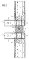
- Figure 2 shows the view of Figure 1 in a sectional view with a cut through the center of the ball foot 4.
- the node part 3 each consists of a bottom or Ceiling piece 8 and four of them bent at right angles Flanges 9, which are each T-shaped and one wider area 10 and a narrower area 11 exhibit.
- Flanges 9 which are each T-shaped and one wider area 10 and a narrower area 11 exhibit.
- the narrower area 11 is at the top a bore 12 is provided, via which riveting with the inside of the rack column 2.
- slots 13 are formed through which each the narrower areas 11 of the flanges 9 inserted and which are dimensioned so that the wider areas 10 of the flanges 9 on the base plate 6 support.
- This construction ensures that Rivet through the holes 12 to the inside of the rack columns 2 the head or footboard 1 to the Rack columns 2 is fixed.
- the stackability of the server racks is between the node pieces 3 of the server racks each provided a ball foot 4, which is fixed to the upper node 3 by a screw 14 is.
- the ball foot On the lower side, the ball foot has a spherical segment-like Bulge 15, which in a corresponding Hole 16 in the node piece when stacking the server racks added and thus the server racks when stacked on top of each other centered.
- the hole 16 also takes place in the upper node 3 Screw connection with the ball foot 4.
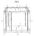
- Figure 3 is a complete server rack in an oblique view shown.
- the ball feet 4 are connected via a frame 17, which at Stack the server racks in between is.
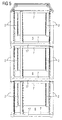
- Figure 4 shows two stacked server racks and figure 5 three server racks stacked on top of each other, each with an intermediate one Stacking frame 17 in side view.
- the rack shown in the figures is for 12 height units each designed.
- the racks When stacked, the racks are only provided on the outside with a bezel frame, which on the one hand represents a disguise and on the other hand it slips the server racks, despite the locking of the ball foot 4 in the bore 16 in the knot part 3, excludes.
Landscapes
- Engineering & Computer Science (AREA)
- Computer Hardware Design (AREA)
- General Engineering & Computer Science (AREA)
- Microelectronics & Electronic Packaging (AREA)
- Combinations Of Kitchen Furniture (AREA)
- Assembled Shelves (AREA)
- Automatic Analysis And Handling Materials Therefor (AREA)
Abstract
Description
Claims (8)
- Serverrack mit vier Racksäulen (2) einem Kopf- und einem Fußteil (1), wobei
die vier Racksäulen (2) untereinander identisch und das Kopfund Fußteil (1) ebenfalls untereinander identisch ausgebildet sind.
dadurch gekennzeichnet, daßa) in das Kopf- beziehungsweise Fußteil (1) von außen in Richtung Racksäule (2) ein Knotenstück (3) eingesteckt ist, das mit der Racksäule (2) verbunden ist undb) das Knotenstück (3) ein Boden-/Deckenstück (8) und zumindest zwei davon rechtwinklig abgebogene Flansche (9) aufweist undc) das Boden- beziehungsweise Deckenstück (8) des Knotenteiles (3) eine Bohrung (16) aufweist. - Serverrack nach Anspruch 1,
dadurch gekennzeichnet, daß
die Racksäulen (2) mit dem Kopf- beziehungweise Fußteil (1) zu vernieten sind. - Serverrack nach Anspruch 1,
dadurch gekennzeichnet, daß
die t-förmigen Flansche aus breiten Bereichen (10) und sich daran anschließenden schmalen Bereichen (11) gebildet sind und die schmalen Bereiche (11) durch entsprechende Schlitze (13) im Kopf- beziehungsweise Fußteil (1) gesteckt sind und sich die breiten Bereiche (10) an dem Kopf- beziehungsweise Fußteil (1) abstützen. - Serverrack nach Anspruch 3,
dadurch gekennzeichnet, daß
eine Vernietung zwischen den schmalen Bereichen (11) der t-förmigen Flansche (9) des Knotenteiles (3) und der Racksäule (2) erfolgt. - Serverrack nach Anspruch 1,
dadurch gekennzeichnet, daß
das Serverrack zur Stapelbarkeit am Bodenstück (8) über die Bohrung (16) mit einem Kugelfuß (4) verbunden ist, welcher mit der Bohrung (16) im Deckenteil (8) des darunter liegenden Serverracks derart zusammenwirkt, daß das darauf liegenden Serverrack in seiner Lage ausgerichtet beziehungsweise zentriert ist. - Stapel bestehend aus Serverracks nach einem der Ansprüche 1 bis 5,
dadurch gekennzeichnet, daß
diese mit einem Blendenrahmen (17) versehen sind, durch welche die einzelnen Serverracks verbunden sind. - Serverrack nach Anspruch 6,
dadurch gekennzeichnet, daß
die Kugelfüße (4) in einem Stapelrahmen (17) integriert sind. - Serverrack nach Anspruch 6 oder 7,
dadurch gekennzeichnet, daß
die gestapelten Serverracks über einen Blendenrahmen verbunden sind.
Applications Claiming Priority (2)
| Application Number | Priority Date | Filing Date | Title |
|---|---|---|---|
| DE2001105287 DE10105287C1 (de) | 2001-02-06 | 2001-02-06 | Serverrack |
| DE10105287 | 2001-02-06 |
Publications (3)
| Publication Number | Publication Date |
|---|---|
| EP1229775A2 true EP1229775A2 (de) | 2002-08-07 |
| EP1229775A3 EP1229775A3 (de) | 2006-08-09 |
| EP1229775B1 EP1229775B1 (de) | 2010-06-09 |
Family
ID=7673002
Family Applications (1)
| Application Number | Title | Priority Date | Filing Date |
|---|---|---|---|
| EP20020001454 Expired - Lifetime EP1229775B1 (de) | 2001-02-06 | 2002-01-21 | Serverrack |
Country Status (2)
| Country | Link |
|---|---|
| EP (1) | EP1229775B1 (de) |
| DE (1) | DE10105287C1 (de) |
Cited By (3)
| Publication number | Priority date | Publication date | Assignee | Title |
|---|---|---|---|---|
| WO2012004453A1 (en) * | 2010-07-09 | 2012-01-12 | Suomen Cnc-Metal Oy | Box-like structure for electric center |
| CN113179677A (zh) * | 2019-06-28 | 2021-07-27 | 西部数据技术公司 | 模块化可调节计算机架 |
| EP4124187A1 (de) * | 2021-07-16 | 2023-01-25 | Google LLC | Gesicherter baugruppenträger-netzwerkträgerbaustein |
Families Citing this family (3)
| Publication number | Priority date | Publication date | Assignee | Title |
|---|---|---|---|---|
| KR101604426B1 (ko) | 2015-01-28 | 2016-03-17 | 주식회사 어니언소프트웨어 | 안내판과 굴뚝 형태의 배기부를 구비하는 서버 랙 |
| PL3500076T3 (pl) | 2017-12-13 | 2020-07-27 | Ovh | Sposób do pozycjonowania stojaka na konstrukcji podstawy |
| CN110799012B (zh) * | 2019-11-06 | 2022-04-05 | 苏州朗威电子机械股份有限公司 | 一种服务器机柜的安装主架及其安装方法 |
Citations (4)
| Publication number | Priority date | Publication date | Assignee | Title |
|---|---|---|---|---|
| DE9421484U1 (de) | 1994-11-23 | 1995-12-21 | Philips Patentverwaltung GmbH, 22335 Hamburg | Gestellschrank |
| DE29814721U1 (de) | 1998-08-17 | 1998-11-05 | Albert Ackermann GmbH & Co. KG, 51643 Gummersbach | Gestell für einen 19" Verteilerschrank |
| DE19811714A1 (de) | 1998-03-18 | 1999-09-30 | Loh Kg Rittal Werk | Bausatz für einen Schaltschrank |
| US6036290A (en) | 1998-03-13 | 2000-03-14 | Hoffman Enclosures, Inc. | Seismic subframe for electrical enclosure |
Family Cites Families (5)
| Publication number | Priority date | Publication date | Assignee | Title |
|---|---|---|---|---|
| FR2495705A1 (fr) * | 1980-12-10 | 1982-06-11 | Hazemeyer Sa | Dispositif d'assemblage rapide et installation electrique comportant une pluralite de coffrets assembles a l'aide de ce dispositif |
| DE4012652A1 (de) * | 1989-06-29 | 1991-01-10 | Hella Kg Hueck & Co | Elektrisches geraet, insbesondere fuer kraftfahrzeuge |
| JP3234860B2 (ja) * | 1996-02-05 | 2001-12-04 | 株式会社日立製作所 | 計算機システム |
| FI961735A0 (fi) * | 1996-04-22 | 1996-04-22 | Control Ab Oy Ensto | Moduluppbyggd kaopa |
| DE19962659C2 (de) * | 1999-12-23 | 2002-03-28 | Knuerr Mechanik Ag | Geräteschrank |
-
2001
- 2001-02-06 DE DE2001105287 patent/DE10105287C1/de not_active Expired - Fee Related
-
2002
- 2002-01-21 EP EP20020001454 patent/EP1229775B1/de not_active Expired - Lifetime
Patent Citations (4)
| Publication number | Priority date | Publication date | Assignee | Title |
|---|---|---|---|---|
| DE9421484U1 (de) | 1994-11-23 | 1995-12-21 | Philips Patentverwaltung GmbH, 22335 Hamburg | Gestellschrank |
| US6036290A (en) | 1998-03-13 | 2000-03-14 | Hoffman Enclosures, Inc. | Seismic subframe for electrical enclosure |
| DE19811714A1 (de) | 1998-03-18 | 1999-09-30 | Loh Kg Rittal Werk | Bausatz für einen Schaltschrank |
| DE29814721U1 (de) | 1998-08-17 | 1998-11-05 | Albert Ackermann GmbH & Co. KG, 51643 Gummersbach | Gestell für einen 19" Verteilerschrank |
Cited By (4)
| Publication number | Priority date | Publication date | Assignee | Title |
|---|---|---|---|---|
| WO2012004453A1 (en) * | 2010-07-09 | 2012-01-12 | Suomen Cnc-Metal Oy | Box-like structure for electric center |
| CN113179677A (zh) * | 2019-06-28 | 2021-07-27 | 西部数据技术公司 | 模块化可调节计算机架 |
| EP4124187A1 (de) * | 2021-07-16 | 2023-01-25 | Google LLC | Gesicherter baugruppenträger-netzwerkträgerbaustein |
| US12309959B2 (en) | 2021-07-16 | 2025-05-20 | Google Llc | Secured, sub-rack network rack building block |
Also Published As
| Publication number | Publication date |
|---|---|
| EP1229775A3 (de) | 2006-08-09 |
| EP1229775B1 (de) | 2010-06-09 |
| DE10105287C1 (de) | 2002-08-29 |
Similar Documents
| Publication | Publication Date | Title |
|---|---|---|
| DE10105287C1 (de) | Serverrack | |
| DE102016212860B4 (de) | Profil zum Verbinden einer Palette mit mindestens einem Palettenaufsetzrahmen sowie Transportsystem umfassend ein derartiges Profil | |
| DE19837184C2 (de) | Gestell für einen 19"-Verteilerschrank | |
| CH687050A5 (de) | Staender fuer die Aufnahme von Gegenstaenden einheitlicher Gestalt. | |
| DE3704042C2 (de) | ||
| DE2161889A1 (de) | Steck- und riegelverbindung | |
| DE202008001486U1 (de) | Zaunsystem | |
| EP0471111B1 (de) | Stapelbare Palette | |
| EP0459135A1 (de) | Bodenplatte für Doppelböden in belüfteten Räumen, insbesondere Reinräumen | |
| EP1171674A1 (de) | Satz von konstruktionselementen zur bildung einer gitterförmigen tragstruktur | |
| DE9409448U1 (de) | Verkaufsaufsteller | |
| DE10206970B4 (de) | Absperrschranke | |
| DE4022747A1 (de) | Verkaufs- und praesentationsregal | |
| DE3118755A1 (de) | "bauelement, sowie hieraus hergestellte baugruppen" | |
| DE4405977A1 (de) | Gerüst mit aufeinanderlegbaren Teilen | |
| DE2038877A1 (de) | Regal | |
| DE29917925U1 (de) | Regalaufbau | |
| DE4417896A1 (de) | Für den Laden- und/oder Ausstellungsbau dienendes Rahmenelement | |
| WO2024240815A1 (de) | Werkstückträgerrahmen und werkstückträgerrahmensystem | |
| DE9315180U1 (de) | Pfosten mit Verbindungsteilen aus Wellpappe oder Pappe | |
| DE20110964U1 (de) | Konstruktionssystem | |
| DE8708765U1 (de) | Einrichtung zum Verbinden der Einlegeböden zweier sich rechtwinklig zueinander erstreckender Regale | |
| DE20202608U1 (de) | Absperrschranke | |
| DE2657210A1 (de) | Regal | |
| DE29705613U1 (de) | Verbindungselement für Gerüst |
Legal Events
| Date | Code | Title | Description |
|---|---|---|---|
| PUAI | Public reference made under article 153(3) epc to a published international application that has entered the european phase |
Free format text: ORIGINAL CODE: 0009012 |
|
| AK | Designated contracting states |
Kind code of ref document: A2 Designated state(s): AT BE CH CY DE DK ES FI FR GB GR IE IT LI LU MC NL PT SE TR |
|
| AX | Request for extension of the european patent |
Free format text: AL;LT;LV;MK;RO;SI |
|
| RAP1 | Party data changed (applicant data changed or rights of an application transferred) |
Owner name: FUJITSU SIEMENS COMPUTERS GMBH |
|
| PUAL | Search report despatched |
Free format text: ORIGINAL CODE: 0009013 |
|
| AK | Designated contracting states |
Kind code of ref document: A3 Designated state(s): AT BE CH CY DE DK ES FI FR GB GR IE IT LI LU MC NL PT SE TR |
|
| AX | Request for extension of the european patent |
Extension state: AL LT LV MK RO SI |
|
| 17P | Request for examination filed |
Effective date: 20070201 |
|
| AKX | Designation fees paid |
Designated state(s): DE FR GB |
|
| 17Q | First examination report despatched |
Effective date: 20090604 |
|
| GRAP | Despatch of communication of intention to grant a patent |
Free format text: ORIGINAL CODE: EPIDOSNIGR1 |
|
| GRAS | Grant fee paid |
Free format text: ORIGINAL CODE: EPIDOSNIGR3 |
|
| GRAA | (expected) grant |
Free format text: ORIGINAL CODE: 0009210 |
|
| AK | Designated contracting states |
Kind code of ref document: B1 Designated state(s): FR GB |
|
| PLBE | No opposition filed within time limit |
Free format text: ORIGINAL CODE: 0009261 |
|
| STAA | Information on the status of an ep patent application or granted ep patent |
Free format text: STATUS: NO OPPOSITION FILED WITHIN TIME LIMIT |
|
| 26N | No opposition filed |
Effective date: 20110310 |
|
| REG | Reference to a national code |
Ref country code: GB Ref legal event code: 746 Effective date: 20110527 |
|
| REG | Reference to a national code |
Ref country code: FR Ref legal event code: PLFP Year of fee payment: 15 |
|
| REG | Reference to a national code |
Ref country code: FR Ref legal event code: PLFP Year of fee payment: 16 |
|
| REG | Reference to a national code |
Ref country code: GB Ref legal event code: 732E Free format text: REGISTERED BETWEEN 20171026 AND 20171101 |
|
| REG | Reference to a national code |
Ref country code: GB Ref legal event code: 732E Free format text: REGISTERED BETWEEN 20171102 AND 20171108 |
|
| REG | Reference to a national code |
Ref country code: FR Ref legal event code: TP Owner name: FUJITSU LIMITED, JP Effective date: 20171113 Ref country code: FR Ref legal event code: CD Owner name: FUJITSU LIMITED, JP Effective date: 20171113 |
|
| REG | Reference to a national code |
Ref country code: FR Ref legal event code: PLFP Year of fee payment: 17 |
|
| PGFP | Annual fee paid to national office [announced via postgrant information from national office to epo] |
Ref country code: FR Payment date: 20191216 Year of fee payment: 19 |
|
| PGFP | Annual fee paid to national office [announced via postgrant information from national office to epo] |
Ref country code: GB Payment date: 20200113 Year of fee payment: 19 |
|
| GBPC | Gb: european patent ceased through non-payment of renewal fee |
Effective date: 20210121 |
|
| PG25 | Lapsed in a contracting state [announced via postgrant information from national office to epo] |
Ref country code: FR Free format text: LAPSE BECAUSE OF NON-PAYMENT OF DUE FEES Effective date: 20210131 |
|
| PG25 | Lapsed in a contracting state [announced via postgrant information from national office to epo] |
Ref country code: GB Free format text: LAPSE BECAUSE OF NON-PAYMENT OF DUE FEES Effective date: 20210121 |