EP1226953A2 - Drucksystem - Google Patents
Drucksystem Download PDFInfo
- Publication number
- EP1226953A2 EP1226953A2 EP02250611A EP02250611A EP1226953A2 EP 1226953 A2 EP1226953 A2 EP 1226953A2 EP 02250611 A EP02250611 A EP 02250611A EP 02250611 A EP02250611 A EP 02250611A EP 1226953 A2 EP1226953 A2 EP 1226953A2
- Authority
- EP
- European Patent Office
- Prior art keywords
- printing
- printing system
- printed
- unit
- Prior art date
- Legal status (The legal status is an assumption and is not a legal conclusion. Google has not performed a legal analysis and makes no representation as to the accuracy of the status listed.)
- Withdrawn
Links
- 238000000034 method Methods 0.000 claims abstract description 16
- 238000004140 cleaning Methods 0.000 claims description 15
- 238000004891 communication Methods 0.000 claims description 12
- 230000004044 response Effects 0.000 claims description 9
- 238000012790 confirmation Methods 0.000 claims description 8
- 238000001514 detection method Methods 0.000 claims description 8
- 230000000007 visual effect Effects 0.000 claims description 5
- 230000005236 sound signal Effects 0.000 claims description 3
- 230000004913 activation Effects 0.000 claims description 2
- 239000012530 fluid Substances 0.000 description 3
- 230000002745 absorbent Effects 0.000 description 2
- 239000002250 absorbent Substances 0.000 description 2
- 230000008901 benefit Effects 0.000 description 2
- 230000000881 depressing effect Effects 0.000 description 2
- 230000000694 effects Effects 0.000 description 2
- 230000006870 function Effects 0.000 description 2
- 239000000463 material Substances 0.000 description 2
- 238000004590 computer program Methods 0.000 description 1
- 230000000994 depressogenic effect Effects 0.000 description 1
- 238000001035 drying Methods 0.000 description 1
- 238000003780 insertion Methods 0.000 description 1
- 230000037431 insertion Effects 0.000 description 1
- 108091008695 photoreceptors Proteins 0.000 description 1
- 238000012545 processing Methods 0.000 description 1
- 230000000284 resting effect Effects 0.000 description 1
Images
Classifications
-
- B—PERFORMING OPERATIONS; TRANSPORTING
- B41—PRINTING; LINING MACHINES; TYPEWRITERS; STAMPS
- B41J—TYPEWRITERS; SELECTIVE PRINTING MECHANISMS, i.e. MECHANISMS PRINTING OTHERWISE THAN FROM A FORME; CORRECTION OF TYPOGRAPHICAL ERRORS
- B41J3/00—Typewriters or selective printing or marking mechanisms characterised by the purpose for which they are constructed
- B41J3/28—Typewriters or selective printing or marking mechanisms characterised by the purpose for which they are constructed for printing downwardly on flat surfaces, e.g. of books, drawings, boxes, envelopes, e.g. flat-bed ink-jet printers
-
- B—PERFORMING OPERATIONS; TRANSPORTING
- B41—PRINTING; LINING MACHINES; TYPEWRITERS; STAMPS
- B41J—TYPEWRITERS; SELECTIVE PRINTING MECHANISMS, i.e. MECHANISMS PRINTING OTHERWISE THAN FROM A FORME; CORRECTION OF TYPOGRAPHICAL ERRORS
- B41J13/00—Devices or arrangements of selective printing mechanisms, e.g. ink-jet printers or thermal printers, specially adapted for supporting or handling copy material in short lengths, e.g. sheets
- B41J13/10—Sheet holders, retainers, movable guides, or stationary guides
- B41J13/14—Aprons or guides for the printing section
Definitions
- the present invention relates to printing systems and in particular printing systems comprising a printing unit and a base station.
- Printing systems are already known that comprise an electronic printing unit and a base station. Such printing systems are most commonly used for printing short, predefined messages or information onto existing documents in a manner analogous to using a rubber stamp. For example, such printing systems may be used to print "Confirmation Copy" on a letter originally sent by facsimile. Such printing systems are more versatile over previously used rubber stamps because a number of different messages may be printed by the same printing system, thus eliminating the need to store a large number of rubber stamps.
- the printing unit comprises a fixed housing with an open face aligning a print location within which an ink jet point head is movable in two dimensions to print an image.
- a printing system comprising a printer unit having housing in which a print head is mounted for movement over a print face defined by the housing and a base station arranged to receive said printer unit, said base station having an opening for receiving an image receiving medium, said opening being located within said base station such that at least a portion of said image receiving medium received within said opening is adjacent said print face, wherein a printing operation can be executed when the printer unit is received in said base station.
- the base station comprises a sensor arranged to provide a detection signal in response to an image receiving medium being placed within said opening and in response to the detection signal the printer unit executes a printing operation a predefined timed time period after the detection signal is provided.
- a confirmation signal may be provided to indicate that a printing operation may be manually initiated.
- the confirmation signal may be a visual signal or an audio signal.
- the base station comprises an alignment device having alignment guides whereby alignment of the image-receiving medium in the opening with the alignment guides facilitates alignment of the image-receiving medium with the print face.
- the alignment device may comprise at least two alignment guides whereby each of the alignment guides facilitates alignment of a different sized image-receiving medium.
- a method of selecting a symbol to be printed by a printer unit from a set of symbols, said set of symbols comprising a plurality of subsets of symbol types, each subset comprising a plurality of symbols of one type comprising: sequentially displaying a first symbol from one or more of said subsets of symbol types and selecting a said subset when a desired symbol type is displayed; sequentially displaying the symbols comprising said selective subset and selecting a desired symbol to be printed.
- Each subset can comprises a plurality of alphabetic characters, a plurality of numeric characters, or a plurality of special characters including a number of punctuation symbols and a number of mathematical symbols.
- each of the alphabetic subsets comprises a plurality of symbols, each symbol being a different representation of the same alphabetic character.
- the sequential display steps are performed in response to the operation of one or more scroll keys located on said printer unit.
- Two scroll keys may be provided, a first scroll key causing the sequential display steps to be formed in a first sequence and a second scroll key causing the sequential display steps to be formed in a second sequence.
- selecting operations are executed by the activation of a select key located on said printer unit.
- a printing system comprising a printing unit connected to a print processor, said print processor arranged to generate a sequence of images to be printed, and said printing unit comprising a communication unit operable to communicate to said print processor information relating to the previously printed image whereby said print processor is further operable to store said communicated information in a memory unit wherein if printing of said sequence of images is interrupted printing can be resumed at the point in the sequence at which the interruption occurred at.
- the sequence of images includes at least one data item having a value that varies in consecutive images in the sequence in a predefined manner and the information communicated from the printing unit to the print processor comprises the value of the at least one data item.
- the information communicated from the printing unit to the print processor comprises the number of images in the sequence that have been printed.
- the communication unit communicates the information to the print processor after each of the images has been printed.
- the communication unit communicates the information to the print processor whenever printing is interrupted.
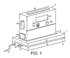
- Figure 1 shows a perspective view of a printing system according to an embodiment of the present invention.
- the system comprises a base station 1 and a print unit 2.
- the base station 1 is substantially rectangular in shape, although it will be appreciated by those skilled in the art that other shapes would equally suffice.
- the base station is intended to be placed on a work surface such as a desk, or the like.
- a recess 4 In what is thus the uppermost surface of the base station 1 there is located a recess 4.
- the recess 4 is shaped to receive a correspondingly shaped portion of the print unit 2.
- the print unit 2 is also substantially rectangular, although again, it will be appreciated by those skilled in the art that the print unit may be of virtually any shape provided that the recess 4 within the base station 1 is correspondingly shaped to receive the appropriate portion of the print unit.
- the base station 1 is connectable to a power supply via a power cable 6.
- the base station 1 also comprises a slot 8 that is dimensioned to be able to receive an image receiving medium of a most commonly used size, for example A4.
- the slot 8 may extend across the full width of the base station 1, as shown in Figure 1, or the base station 1 may be of such a size that the slot 8 forms a discrete opening within the base station, in a manner similar to a letter box.
- the slot 8 extends sufficiently into the base station 1 such that at least a portion of it extends under the print unit 2 when the print unit is located within the recess 4 of the base station 1.
- the recess 4 extends through the base station 1 such that it communicates with the slot 8.
- means are provided (not shown) to prevent the print unit 2 from resting on the lower surface of the slot 8 when the print unit 2 is located within the recess 4 of the base station 1.
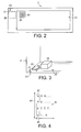
- the bottom surface of the print unit 2 that is the surface that is inserted into the recess 4 of the base station 1, is illustrated in Figure 2.
- an aperture 20, or print face that defines the area over which printing may be executed by the print unit 2.
- a print head 24 which in the embodiment shown, is of the ink jet type and comprises a plurality of individual ink drop outlets 26 that allow a discrete image to be created, for example a single alphanumeric character.
- the print head 24 is moveable by transport means (not shown) such that it may move across the plane of the print face 20 in two orthogonal directions.
- the printer 24 allows a plurality of lines of images to be generated by the printer 24 such that a plurality of lines of discrete characters may be printed or alternatively characters larger than the print head 24 itself may also be generated. It will be appreciated that the print head 24 may also be limited to movement across the print face 20 in a single direction only, thus only having the ability to print a single line of characters.
- the print face 20 does not extend across the entirety of the lower surface of the print head 2 and located on part of a remaining portion of the lower surface and located within the body of the print unit 2, is a print head cleaning station 22.
- the print head 24 is moveable to the print head cleaning station 22 and in doing so effects a cleaning operation on the lowermost surface of the print head 24.
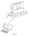
- the print head cleaning station 22 may comprise a pad of felt or other similar absorbent material that removes any excess printing fluid from the printer 24 when it is brought into registration with the print head cleaning station 22. Such a pad of absorbent material is shown in Figure 3, which shows an enlarged view of the print head cleaning station and print head of Figure 2.
- the print unit 2 may be removed from the recess 4 in the base station 1 and placed on the piece of paper so that the print face is at the location at which the printing is desired to appear.
- the printing operation is then manually initiated by depressing the print button 14 located on the uppermost surface of the print unit 2.
- the print unit 2 may then be returned to the base station 1.
- a sensor for example a microswitch, (not shown) located within the recess 4 of the base station 1
- a print head cleaning operation is executed by the print head 24 of the print unit 2 being driven across the print head cleaning station 22, thereby removing any excess printing fluid from the print head 24.
- a signal may be generated by the print unit that indicates to the user that the print unit should be replaced on the base station 1. This signal may be generated either after a predetermined time period after the last printing operation has been executed, or after a predetermined number of printing operations have been executed, and has the purpose of reminding the user to replace the print unit 2 in the base station 1 to enable a print head cleaning operation to be executed, thus avoiding the print head from drying out, or becoming clogged with printing fluid.
- the signal denoted the head-cleaning signal may either be a visual signal or an audio signal.
- An alternative method of printing onto a piece of paper or document is also possible with embodiments of the present invention.
- the print unit 2 remains, or is replaced, in the recess 4 of the base station 1 and a piece of paper or a document is introduced into the slot 8 within the base station 1.
- the paper is fully introduced into the slot 8 such that it underlies the print face of the print unit 2 that is located in the recess 4 of the base station 1.
- a sensor may be provided within the base station 1 that detects when a piece of paper has been introduced into the slot 8.
- the sensor may be, for example, a simple light emitting diode/photo receptor arrangement that simply detects the insertion of a piece of paper into the slot 8, or it may be a micro switch located at the far extremity of the slot 8 and arranged to be activated by the leading edge of the paper that is introduced into the slot.
- the sensor produces a signal when a piece of paper is detected in the slot 8, the signal alternatively either being transmitted to the print unit 2 and causing a print operation to be executed automatically, or may cause a audible or visual signal to be generated by the printing system as confirmation to the user that the printing operation may be initiated by depressing the print operation button 14.
- an LED 16 is shown on the base station 1 that provides a visual confirmation signal.
- an alignment device 10 is provided on the base station 1 and comprises an essentially flat element attached to the base station 1 so that an edge of a piece of paper inserted into the slot 8 closely overlies a portion of the alignment device 10.
- the alignment device includes at least one alignment mark 12 that is positioned on the alignment device such that when the edge of a piece of paper of a normal size, for example A4 or quarto, is aligned with the alignment mark 12 the printing operation will be executed in the centre of the piece of paper, or document.
- the alignment device 10 may be removable from the base station 1 such that other alignment devices corresponding to other sizes of pieces of paper, for example envelopes, may be inserted to facilitate the alignment of the print unit 2 with such other sized pieces of paper.
- the print unit 2 may be connected to the base station 1 by a power cable (not shown) that conveys power from the base station to the print unit, enabling operation of the print unit 2.
- a more preferred arrangement is that the print unit 2 incorporates a battery pack 18.
- the battery pack 18 may be arranged to receive conventional batteries in a known manner to provide power to the print unit 2, or may comprise, or be arranged to receive, a rechargeable battery unit.
- the base station 1 may incorporate a power connector (not shown) that engages with a corresponding connector (not shown) on the print unit 2 such that the battery pack 18 may receive a recharging current via the base station 1 whenever the print unit 2 is located within the recess 4 of base station 1.
- the system is arranged to be capable of printing a number of different information items.
- information items that may be printed include "Confidential”, “Received”, the current time and/or date, or even a bar code.
- the print information required to drive the print head 24 of the print unit 2 to print such information items is stored in a memory unit within the print unit 2.
- Scroll buttons 28;29 and a select button 30 are provided on a face of the print unit 2 and are used in conjunction with a display 32, also mounted on the print unit 2.
- the scroll buttons 28; 29 are operated by the user to sequentially display on the display 32 the desired data items that may be printed.
- the print unit 2 may be arranged to receive a memory card 34 of a known type, the memory card containing the information items to be printed, or alternatively additional data items that may be printed. It is envisaged that the data items held on the data memory card 34, or the memory unit within the print unit 2, are predetermined items selected by the manufacturer. It will also be appreciated that a number of different memory cards 34 may be supplied, each bearing different data items covering a wide range of applications.
- the scroll buttons 28;29, select button 30 and display screen 32 can also be used to select or adjust the print properties of the printed data items or certain functions of the print unit 2.
- the buttons and display screen 32 may be used to adjust or set the time and/or date, or the format of the date i.e. DD/MM/YYYY, for example.
- pictograms are displayed on the display screen 32 that denote the function to be executed if selected by the select button 30.
- a pictogram of an alphanumeric character displayed so as to be a particularly dark, or in relief may indicate that the selected data item is to be printed in bold print.
- the pictograms are the same as, or similar to, existing pictograms used in existing word processing or other computer programs.
- users may define their own data items that are to be printed, the defined data items being subsequently stored on either a memory card 34 or the memory unit of the print unit 2, as applicable.
- a data item for printing individual alphanumeric characters or symbols are selected from a pre-stored menu using the scroll buttons 28;29, select button 30 and display screen 32.
- the number of characters and symbols that may be used is potentially quite large and is unlikely to be able to display them all at once on the display screen 32. Therefore, to minimise the number of scrolling and selecting operations the user must perform to select each character or symbol the characters and symbols are arranged in the menu in a particular manner.
- the characters and symbols are grouped together into subsets according to the type of character or symbol. For example, a subset may comprise of a number of versions of the letter "A", each one having the various accents applied to it that are used in the various different languages. A further subset may comprise of a number of the letters "E" with such accents also applied and a further subset may also comprise of numeric digits 0-9 and for mathematical symbols, and so on.
- this method has the further advantage that symbol sets for various different languages can be stored and displayed without any particular bias as to which language is displayed first. That is to say that a user wishing to define a data item in the French language is not required to scroll past all of the symbols that are appropriate to use only in a different language, such as German for example.
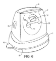
- the printing system has the additional capability of communicating with an auxiliary image generating processor, such as a desk top PC or the like, as illustrated in Figure 5.
- the means for communicating between the processor 45 and the printing system may be any known method such as a cable connection, infrared connection, or radio communications system, such as Bluetooth.
- the communication means may be connected to either the base station 1 or the print unit 2. In these embodiments the image or data item that is desired to be printed is generated by the processor 45 and transmitted to the print unit 2.
- One application for such an arrangement is the generation and printing of a sequence of data items in which only a single piece of information changes between each data item within the sequence.
- One such example is the generation and printing of bar codes that include a sequentially increasing serial number for an item.
- either the print unit 2 or the base station 1 includes what will be referred to hereinafter as a counter module.
- the counter module is operable to maintain a record of the value of the last printed piece of variable data within a sequence of data items and to communicate this information via communication means back to the image generating processor 45.
- the counter module may comprise a further processor and communication interface (not shown). Communication of the state of the previously printed data variable may be communicated to the image generating processor 45 after each data item in a sequence is printed, or alternatively may be only communicated to the image generating processor 45 whenever the printing of the sequence of data items is interrupted. It will of course be appreciated that other schemes of communicating the information may also be adopted.
- the communicated information is stored by the image generating processor 45 and is thus available to restart printing of a sequence at the appropriate point after the sequence has been previously interrupted.
- the counter module may simply maintain track of the total number of data items within a sequence that have been printed, this information also being usable by the image generating processor 45 to restart an interrupted sequence at the appropriate point.
- the printing of any sequence of data items may be interrupted and restarted regardless of the information content of the data items.
- one such application would be the printing of address details from a database where although the information content of each record in the database differs entirely, as the records are in a structured order then by maintaining a count of the number of records printed an interrupted print operation may be successfully resumed at the correct point.
Landscapes
- Accessory Devices And Overall Control Thereof (AREA)
- Printers Characterized By Their Purpose (AREA)
Applications Claiming Priority (2)
| Application Number | Priority Date | Filing Date | Title |
|---|---|---|---|
| GB0102360 | 2001-01-30 | ||
| GB0102360A GB2372480A (en) | 2001-01-30 | 2001-01-30 | Portable inkjet printer having a printer unit and a base station wherein the station includes an opening to receive an image receiving medium for printing |
Publications (2)
| Publication Number | Publication Date |
|---|---|
| EP1226953A2 true EP1226953A2 (de) | 2002-07-31 |
| EP1226953A3 EP1226953A3 (de) | 2003-10-22 |
Family
ID=9907795
Family Applications (1)
| Application Number | Title | Priority Date | Filing Date |
|---|---|---|---|
| EP02250611A Withdrawn EP1226953A3 (de) | 2001-01-30 | 2002-01-29 | Drucksystem |
Country Status (4)
| Country | Link |
|---|---|
| US (1) | US20020101610A1 (de) |
| EP (1) | EP1226953A3 (de) |
| DE (1) | DE20111008U1 (de) |
| GB (1) | GB2372480A (de) |
Families Citing this family (3)
| Publication number | Priority date | Publication date | Assignee | Title |
|---|---|---|---|---|
| EP1977341A2 (de) * | 2006-01-24 | 2008-10-08 | ZIH Corporation | Globales drucksystem und verwendungsverfahren dafür |
| JP6969359B2 (ja) * | 2017-12-21 | 2021-11-24 | カシオ計算機株式会社 | 印刷ユニット |
| AT16843U1 (de) | 2019-11-22 | 2020-11-15 | Colop Digital Gmbh | Zubehörvorrichtung für ein elektronisches Markiergerät |
Family Cites Families (17)
| Publication number | Priority date | Publication date | Assignee | Title |
|---|---|---|---|---|
| US4428065A (en) * | 1979-06-28 | 1984-01-24 | Xerox Corporation | Data processing system with multiple display apparatus |
| US5171092A (en) * | 1987-07-06 | 1992-12-15 | Canon Kabushiki Kaisha | Printing apparatus that stores externally supplied fonts |
| FR2675739A1 (fr) * | 1991-04-26 | 1992-10-30 | Aem Megras | Timbre programmable pour imprimer des signes sur un support. |
| JP2551876Y2 (ja) * | 1991-09-06 | 1997-10-27 | ローム株式会社 | 携帯式プリンタを使用したテーププリンタ装置 |
| GB9207287D0 (en) * | 1992-04-02 | 1992-05-13 | Esselte Dymo Nv | Printing device |
| JP3600634B2 (ja) * | 1994-05-18 | 2004-12-15 | ペンタックス株式会社 | 感熱プリンタ |
| US5634730A (en) * | 1995-11-06 | 1997-06-03 | Bobry; Howard H. | Hand-held electronic printer |
| US5923763A (en) * | 1996-03-21 | 1999-07-13 | Walker Asset Management Limited Partnership | Method and apparatus for secure document timestamping |
| US5832331A (en) * | 1996-04-08 | 1998-11-03 | Minolta Co., Ltd. | Image forming apparatus resuming an interrupted image forming job when power is restored and at timings dependent upon detection and non-detection of a new image forming job |
| GB2314957A (en) * | 1996-07-05 | 1998-01-14 | Esselte Nv | Label printer |
| JPH1029345A (ja) * | 1996-07-16 | 1998-02-03 | Brother Ind Ltd | 印字装置 |
| JPH1158848A (ja) * | 1997-08-26 | 1999-03-02 | Brother Ind Ltd | 手動走査兼用画像形成装置 |
| GB2343656B (en) * | 1998-11-13 | 2002-11-13 | Esselte Nv | A manually positioned printer with an alignment means |
| DE69904434T2 (de) * | 1999-02-19 | 2003-10-30 | Hewlett-Packard Co. (N.D.Ges.D.Staates Delaware), Palo Alto | Automatische Druckträgerhandhabung |
| US6145376A (en) * | 1999-03-25 | 2000-11-14 | Hewlett-Packard Company | Paper size detection using ultrasound |
| JP3335991B2 (ja) * | 2000-08-21 | 2002-10-21 | オリンパス光学工業株式会社 | プリンタ装置 |
| US7310156B2 (en) * | 2001-02-01 | 2007-12-18 | Canon Kabushiki Kaisha | Printing system, printing method, digital camera, storage medium and program for printing method, and printing control apparatus |
-
2001
- 2001-01-30 GB GB0102360A patent/GB2372480A/en not_active Withdrawn
- 2001-07-03 DE DE20111008U patent/DE20111008U1/de not_active Expired - Lifetime
- 2001-08-02 US US09/919,842 patent/US20020101610A1/en not_active Abandoned
-
2002
- 2002-01-29 EP EP02250611A patent/EP1226953A3/de not_active Withdrawn
Also Published As
| Publication number | Publication date |
|---|---|
| US20020101610A1 (en) | 2002-08-01 |
| GB0102360D0 (en) | 2001-03-14 |
| EP1226953A3 (de) | 2003-10-22 |
| DE20111008U1 (de) | 2001-10-11 |
| GB2372480A (en) | 2002-08-28 |
Similar Documents
| Publication | Publication Date | Title |
|---|---|---|
| US20030174177A1 (en) | Printing apparatus, menu-adding method for the printing apparatus, printing system, and storage media | |
| US6644873B2 (en) | Printing apparatus and printing method | |
| EP1739628A3 (de) | Bedienfeldetikett für eine Frankierungsdruckvorrichtung | |
| US8670160B2 (en) | Printing device for printing conceal pattern on character string printed on printed object based on said character string, and printing method and recording medium for the same | |
| US20020105673A1 (en) | Printing apparatus and printing method | |
| US6115024A (en) | Image display device | |
| EP1226953A2 (de) | Drucksystem | |
| CN104781079A (zh) | 打印装置 | |
| WO2000074941A1 (en) | Device to id photographs | |
| SG138461A1 (en) | Interactive printer | |
| JP5321898B2 (ja) | テープ印刷装置、ラベルの印刷方法、ラベルの印刷方法のプログラムが記憶された記憶媒体 | |
| EP0455336B1 (de) | Datenverarbeitungsgerät und Verfahren | |
| US20030011808A1 (en) | Printable personal digital assistant | |
| JP2005059293A (ja) | 印刷装置 | |
| EP1607226B1 (de) | Drucksteuerung und drucksteuerprogramm | |
| EP0372592A2 (de) | Vorrichtung mit geringer Abmessung zur Zeicheneingabe und Verfahren dafür | |
| JPH06314137A (ja) | ハンディ情報処理装置 | |
| JP2001001295A (ja) | シールカッティングマシン | |
| JP2021157710A (ja) | テープ印刷装置、情報処理装置、テープ印刷装置の制御方法、およびプログラム | |
| EP1857281B1 (de) | Eingabevorrichtung, drucker und kartengehäuse mit druckfunktion | |
| US20180170069A1 (en) | Recording medium, label image preparing method, and label image preparing apparatus | |
| EP1231561B1 (de) | Drucksystem | |
| CA2508668C (en) | Systems, methods and apparatuses for real-time tracking of packages | |
| EP1615161A2 (de) | Systeme, Verfahren und Geräte zur Echtzeitverfolgung von Paketen | |
| CN1983072A (zh) | 设置有安装在可拆卸组件上的存储设备的图像形成装置 |
Legal Events
| Date | Code | Title | Description |
|---|---|---|---|
| PUAI | Public reference made under article 153(3) epc to a published international application that has entered the european phase |
Free format text: ORIGINAL CODE: 0009012 |
|
| AK | Designated contracting states |
Kind code of ref document: A2 Designated state(s): AT BE CH CY DE DK ES FI FR GB GR IE IT LI LU MC NL PT SE TR |
|
| AX | Request for extension of the european patent |
Free format text: AL;LT;LV;MK;RO;SI |
|
| PUAL | Search report despatched |
Free format text: ORIGINAL CODE: 0009013 |
|
| AK | Designated contracting states |
Kind code of ref document: A3 Designated state(s): AT BE CH CY DE DK ES FI FR GB GR IE IT LI LU MC NL PT SE TR |
|
| AX | Request for extension of the european patent |
Extension state: AL LT LV MK RO SI |
|
| RAP1 | Party data changed (applicant data changed or rights of an application transferred) |
Owner name: ESSELTE |
|
| 17P | Request for examination filed |
Effective date: 20040422 |
|
| AKX | Designation fees paid |
Designated state(s): AT BE CH CY DE DK ES FI FR GB GR IE IT LI LU MC NL PT SE TR |
|
| 17Q | First examination report despatched |
Effective date: 20040705 |
|
| STAA | Information on the status of an ep patent application or granted ep patent |
Free format text: STATUS: THE APPLICATION IS DEEMED TO BE WITHDRAWN |
|
| 18D | Application deemed to be withdrawn |
Effective date: 20041106 |