EP1226588B1 - Elektrisch leitende härtbare harzzusammensetzung , daraus hergestelltes gehärtetes produkt und unter verwendung der zusammensetzung hergestelltes produkt - Google Patents
Elektrisch leitende härtbare harzzusammensetzung , daraus hergestelltes gehärtetes produkt und unter verwendung der zusammensetzung hergestelltes produkt Download PDFInfo
- Publication number
- EP1226588B1 EP1226588B1 EP01934556A EP01934556A EP1226588B1 EP 1226588 B1 EP1226588 B1 EP 1226588B1 EP 01934556 A EP01934556 A EP 01934556A EP 01934556 A EP01934556 A EP 01934556A EP 1226588 B1 EP1226588 B1 EP 1226588B1
- Authority
- EP
- European Patent Office
- Prior art keywords
- curable resin
- resin composition
- component
- electroconductive
- less
- Prior art date
- Legal status (The legal status is an assumption and is not a legal conclusion. Google has not performed a legal analysis and makes no representation as to the accuracy of the status listed.)
- Expired - Lifetime
Links
- 239000011342 resin composition Substances 0.000 title claims abstract description 83
- 239000000203 mixture Substances 0.000 title description 20
- OKTJSMMVPCPJKN-UHFFFAOYSA-N Carbon Chemical compound [C] OKTJSMMVPCPJKN-UHFFFAOYSA-N 0.000 claims abstract description 157
- 229920005989 resin Polymers 0.000 claims abstract description 61
- 239000011347 resin Substances 0.000 claims abstract description 61
- 229910002804 graphite Inorganic materials 0.000 claims abstract description 48
- 239000010439 graphite Substances 0.000 claims abstract description 48
- ZOXJGFHDIHLPTG-UHFFFAOYSA-N Boron Chemical compound [B] ZOXJGFHDIHLPTG-UHFFFAOYSA-N 0.000 claims abstract description 39
- 229910052796 boron Inorganic materials 0.000 claims abstract description 36
- 239000013078 crystal Substances 0.000 claims abstract description 12
- 238000000034 method Methods 0.000 claims description 57
- 239000002245 particle Substances 0.000 claims description 57
- 239000000843 powder Substances 0.000 claims description 40
- 239000000835 fiber Substances 0.000 claims description 30
- 239000003822 epoxy resin Substances 0.000 claims description 23
- 229920000647 polyepoxide Polymers 0.000 claims description 23
- 239000002041 carbon nanotube Substances 0.000 claims description 22
- 229910021393 carbon nanotube Inorganic materials 0.000 claims description 22
- -1 allyl ester Chemical class 0.000 claims description 21
- 230000008569 process Effects 0.000 claims description 21
- VNWKTOKETHGBQD-UHFFFAOYSA-N methane Chemical compound C VNWKTOKETHGBQD-UHFFFAOYSA-N 0.000 claims description 20
- 239000005011 phenolic resin Substances 0.000 claims description 20
- 239000000178 monomer Substances 0.000 claims description 18
- 229920000049 Carbon (fiber) Polymers 0.000 claims description 17
- 239000004917 carbon fiber Substances 0.000 claims description 17
- 238000010079 rubber tapping Methods 0.000 claims description 17
- 229920001567 vinyl ester resin Polymers 0.000 claims description 17
- 229920001568 phenolic resin Polymers 0.000 claims description 16
- KXGFMDJXCMQABM-UHFFFAOYSA-N 2-methoxy-6-methylphenol Chemical compound [CH]OC1=CC=CC([CH])=C1O KXGFMDJXCMQABM-UHFFFAOYSA-N 0.000 claims description 15
- 238000000748 compression moulding Methods 0.000 claims description 15
- 239000000446 fuel Substances 0.000 claims description 13
- 239000012808 vapor phase Substances 0.000 claims description 13
- PPBRXRYQALVLMV-UHFFFAOYSA-N Styrene Chemical group C=CC1=CC=CC=C1 PPBRXRYQALVLMV-UHFFFAOYSA-N 0.000 claims description 8
- 239000003795 chemical substances by application Substances 0.000 claims description 8
- 238000001721 transfer moulding Methods 0.000 claims description 8
- 238000001746 injection moulding Methods 0.000 claims description 7
- 230000035699 permeability Effects 0.000 claims description 7
- 239000007870 radical polymerization initiator Substances 0.000 claims description 7
- 229920006337 unsaturated polyester resin Polymers 0.000 claims description 7
- QTWJRLJHJPIABL-UHFFFAOYSA-N 2-methylphenol;3-methylphenol;4-methylphenol Chemical compound CC1=CC=C(O)C=C1.CC1=CC=CC(O)=C1.CC1=CC=CC=C1O QTWJRLJHJPIABL-UHFFFAOYSA-N 0.000 claims description 5
- 229930003836 cresol Natural products 0.000 claims description 5
- 125000005396 acrylic acid ester group Chemical group 0.000 claims description 4
- 125000005397 methacrylic acid ester group Chemical group 0.000 claims description 4
- 239000000945 filler Substances 0.000 abstract description 2
- 239000000571 coke Substances 0.000 description 36
- 239000000523 sample Substances 0.000 description 24
- 238000005087 graphitization Methods 0.000 description 18
- 229910052799 carbon Inorganic materials 0.000 description 14
- 238000001723 curing Methods 0.000 description 13
- 239000000463 material Substances 0.000 description 11
- 238000010438 heat treatment Methods 0.000 description 10
- 238000006243 chemical reaction Methods 0.000 description 9
- 238000002156 mixing Methods 0.000 description 8
- 238000010298 pulverizing process Methods 0.000 description 8
- 239000007858 starting material Substances 0.000 description 8
- 239000007789 gas Substances 0.000 description 7
- 238000004519 manufacturing process Methods 0.000 description 6
- 238000005259 measurement Methods 0.000 description 6
- XLYOFNOQVPJJNP-UHFFFAOYSA-N water Chemical compound O XLYOFNOQVPJJNP-UHFFFAOYSA-N 0.000 description 6
- 239000003054 catalyst Substances 0.000 description 5
- 230000006835 compression Effects 0.000 description 5
- 238000007906 compression Methods 0.000 description 5
- 238000009826 distribution Methods 0.000 description 5
- 239000004071 soot Substances 0.000 description 5
- KKEYFWRCBNTPAC-UHFFFAOYSA-N Terephthalic acid Chemical compound OC(=O)C1=CC=C(C(O)=O)C=C1 KKEYFWRCBNTPAC-UHFFFAOYSA-N 0.000 description 4
- 239000002253 acid Substances 0.000 description 4
- 230000015572 biosynthetic process Effects 0.000 description 4
- IISBACLAFKSPIT-UHFFFAOYSA-N bisphenol A Chemical compound C=1C=C(O)C=CC=1C(C)(C)C1=CC=C(O)C=C1 IISBACLAFKSPIT-UHFFFAOYSA-N 0.000 description 4
- INAHAJYZKVIDIZ-UHFFFAOYSA-N boron carbide Chemical compound B12B3B4C32B41 INAHAJYZKVIDIZ-UHFFFAOYSA-N 0.000 description 4
- 230000000052 comparative effect Effects 0.000 description 4
- 230000003247 decreasing effect Effects 0.000 description 4
- 239000006185 dispersion Substances 0.000 description 4
- 239000003999 initiator Substances 0.000 description 4
- QQVIHTHCMHWDBS-UHFFFAOYSA-N isophthalic acid Chemical compound OC(=O)C1=CC=CC(C(O)=O)=C1 QQVIHTHCMHWDBS-UHFFFAOYSA-N 0.000 description 4
- 230000000704 physical effect Effects 0.000 description 4
- 239000002861 polymer material Substances 0.000 description 4
- 239000002994 raw material Substances 0.000 description 4
- 238000000926 separation method Methods 0.000 description 4
- NIXOWILDQLNWCW-UHFFFAOYSA-M Acrylate Chemical compound [O-]C(=O)C=C NIXOWILDQLNWCW-UHFFFAOYSA-M 0.000 description 3
- IJGRMHOSHXDMSA-UHFFFAOYSA-N Atomic nitrogen Chemical compound N#N IJGRMHOSHXDMSA-UHFFFAOYSA-N 0.000 description 3
- 229910052580 B4C Inorganic materials 0.000 description 3
- UHOVQNZJYSORNB-UHFFFAOYSA-N Benzene Chemical compound C1=CC=CC=C1 UHOVQNZJYSORNB-UHFFFAOYSA-N 0.000 description 3
- RYGMFSIKBFXOCR-UHFFFAOYSA-N Copper Chemical compound [Cu] RYGMFSIKBFXOCR-UHFFFAOYSA-N 0.000 description 3
- LYCAIKOWRPUZTN-UHFFFAOYSA-N Ethylene glycol Chemical compound OCCO LYCAIKOWRPUZTN-UHFFFAOYSA-N 0.000 description 3
- DNIAPMSPPWPWGF-UHFFFAOYSA-N Propylene glycol Chemical compound CC(O)CO DNIAPMSPPWPWGF-UHFFFAOYSA-N 0.000 description 3
- XUIMIQQOPSSXEZ-UHFFFAOYSA-N Silicon Chemical compound [Si] XUIMIQQOPSSXEZ-UHFFFAOYSA-N 0.000 description 3
- YXFVVABEGXRONW-UHFFFAOYSA-N Toluene Chemical compound CC1=CC=CC=C1 YXFVVABEGXRONW-UHFFFAOYSA-N 0.000 description 3
- 229910052782 aluminium Inorganic materials 0.000 description 3
- XAGFODPZIPBFFR-UHFFFAOYSA-N aluminium Chemical compound [Al] XAGFODPZIPBFFR-UHFFFAOYSA-N 0.000 description 3
- 238000004458 analytical method Methods 0.000 description 3
- 239000012298 atmosphere Substances 0.000 description 3
- 229910052790 beryllium Inorganic materials 0.000 description 3
- ATBAMAFKBVZNFJ-UHFFFAOYSA-N beryllium atom Chemical compound [Be] ATBAMAFKBVZNFJ-UHFFFAOYSA-N 0.000 description 3
- 125000004432 carbon atom Chemical group C* 0.000 description 3
- 230000008859 change Effects 0.000 description 3
- 229910052802 copper Inorganic materials 0.000 description 3
- 239000010949 copper Substances 0.000 description 3
- 230000007797 corrosion Effects 0.000 description 3
- 238000005260 corrosion Methods 0.000 description 3
- 238000011156 evaluation Methods 0.000 description 3
- 238000001095 inductively coupled plasma mass spectrometry Methods 0.000 description 3
- 238000011835 investigation Methods 0.000 description 3
- 239000010410 layer Substances 0.000 description 3
- NJPPVKZQTLUDBO-UHFFFAOYSA-N novaluron Chemical compound C1=C(Cl)C(OC(F)(F)C(OC(F)(F)F)F)=CC=C1NC(=O)NC(=O)C1=C(F)C=CC=C1F NJPPVKZQTLUDBO-UHFFFAOYSA-N 0.000 description 3
- 150000001451 organic peroxides Chemical class 0.000 description 3
- BASFCYQUMIYNBI-UHFFFAOYSA-N platinum Chemical compound [Pt] BASFCYQUMIYNBI-UHFFFAOYSA-N 0.000 description 3
- 238000000790 scattering method Methods 0.000 description 3
- 229910052710 silicon Inorganic materials 0.000 description 3
- 239000010703 silicon Substances 0.000 description 3
- 239000002356 single layer Substances 0.000 description 3
- 239000000243 solution Substances 0.000 description 3
- 238000003860 storage Methods 0.000 description 3
- 238000001149 thermolysis Methods 0.000 description 3
- MYRTYDVEIRVNKP-UHFFFAOYSA-N 1,2-Divinylbenzene Chemical compound C=CC1=CC=CC=C1C=C MYRTYDVEIRVNKP-UHFFFAOYSA-N 0.000 description 2
- XMNIXWIUMCBBBL-UHFFFAOYSA-N 2-(2-phenylpropan-2-ylperoxy)propan-2-ylbenzene Chemical compound C=1C=CC=CC=1C(C)(C)OOC(C)(C)C1=CC=CC=C1 XMNIXWIUMCBBBL-UHFFFAOYSA-N 0.000 description 2
- FUGYGGDSWSUORM-UHFFFAOYSA-N 4-hydroxystyrene Chemical compound OC1=CC=C(C=C)C=C1 FUGYGGDSWSUORM-UHFFFAOYSA-N 0.000 description 2
- 239000004641 Diallyl-phthalate Substances 0.000 description 2
- LFQSCWFLJHTTHZ-UHFFFAOYSA-N Ethanol Chemical compound CCO LFQSCWFLJHTTHZ-UHFFFAOYSA-N 0.000 description 2
- VZCYOOQTPOCHFL-OWOJBTEDSA-N Fumaric acid Chemical compound OC(=O)\C=C\C(O)=O VZCYOOQTPOCHFL-OWOJBTEDSA-N 0.000 description 2
- PEDCQBHIVMGVHV-UHFFFAOYSA-N Glycerine Chemical compound OCC(O)CO PEDCQBHIVMGVHV-UHFFFAOYSA-N 0.000 description 2
- QIGBRXMKCJKVMJ-UHFFFAOYSA-N Hydroquinone Chemical compound OC1=CC=C(O)C=C1 QIGBRXMKCJKVMJ-UHFFFAOYSA-N 0.000 description 2
- QAOWNCQODCNURD-UHFFFAOYSA-N Sulfuric acid Chemical compound OS(O)(=O)=O QAOWNCQODCNURD-UHFFFAOYSA-N 0.000 description 2
- 238000002441 X-ray diffraction Methods 0.000 description 2
- 239000000654 additive Substances 0.000 description 2
- 230000000996 additive effect Effects 0.000 description 2
- WNLRTRBMVRJNCN-UHFFFAOYSA-N adipic acid Chemical compound OC(=O)CCCCC(O)=O WNLRTRBMVRJNCN-UHFFFAOYSA-N 0.000 description 2
- XXROGKLTLUQVRX-UHFFFAOYSA-N allyl alcohol Chemical compound OCC=C XXROGKLTLUQVRX-UHFFFAOYSA-N 0.000 description 2
- QUDWYFHPNIMBFC-UHFFFAOYSA-N bis(prop-2-enyl) benzene-1,2-dicarboxylate Chemical compound C=CCOC(=O)C1=CC=CC=C1C(=O)OCC=C QUDWYFHPNIMBFC-UHFFFAOYSA-N 0.000 description 2
- WERYXYBDKMZEQL-UHFFFAOYSA-N butane-1,4-diol Chemical compound OCCCCO WERYXYBDKMZEQL-UHFFFAOYSA-N 0.000 description 2
- DJKGDNKYTKCJKD-UHFFFAOYSA-N chlorendic acid Chemical compound ClC1=C(Cl)C2(Cl)C(C(=O)O)C(C(O)=O)C1(Cl)C2(Cl)Cl DJKGDNKYTKCJKD-UHFFFAOYSA-N 0.000 description 2
- 239000002131 composite material Substances 0.000 description 2
- 150000001875 compounds Chemical class 0.000 description 2
- 230000000694 effects Effects 0.000 description 2
- 238000005516 engineering process Methods 0.000 description 2
- 238000011049 filling Methods 0.000 description 2
- 230000005484 gravity Effects 0.000 description 2
- 239000011261 inert gas Substances 0.000 description 2
- 238000004898 kneading Methods 0.000 description 2
- 238000001000 micrograph Methods 0.000 description 2
- 229920003986 novolac Polymers 0.000 description 2
- 150000002978 peroxides Chemical class 0.000 description 2
- 229920000642 polymer Polymers 0.000 description 2
- 239000011802 pulverized particle Substances 0.000 description 2
- CYIDZMCFTVVTJO-UHFFFAOYSA-N pyromellitic acid Chemical compound OC(=O)C1=CC(C(O)=O)=C(C(O)=O)C=C1C(O)=O CYIDZMCFTVVTJO-UHFFFAOYSA-N 0.000 description 2
- 239000010948 rhodium Substances 0.000 description 2
- 238000007493 shaping process Methods 0.000 description 2
- 239000002904 solvent Substances 0.000 description 2
- 239000000126 substance Substances 0.000 description 2
- CIHOLLKRGTVIJN-UHFFFAOYSA-N tert‐butyl hydroperoxide Chemical compound CC(C)(C)OO CIHOLLKRGTVIJN-UHFFFAOYSA-N 0.000 description 2
- 229920001187 thermosetting polymer Polymers 0.000 description 2
- VZCYOOQTPOCHFL-UHFFFAOYSA-N trans-butenedioic acid Natural products OC(=O)C=CC(O)=O VZCYOOQTPOCHFL-UHFFFAOYSA-N 0.000 description 2
- ARCGXLSVLAOJQL-UHFFFAOYSA-N trimellitic acid Chemical compound OC(=O)C1=CC=C(C(O)=O)C(C(O)=O)=C1 ARCGXLSVLAOJQL-UHFFFAOYSA-N 0.000 description 2
- 238000002604 ultrasonography Methods 0.000 description 2
- KNDQHSIWLOJIGP-UMRXKNAASA-N (3ar,4s,7r,7as)-rel-3a,4,7,7a-tetrahydro-4,7-methanoisobenzofuran-1,3-dione Chemical compound O=C1OC(=O)[C@@H]2[C@H]1[C@]1([H])C=C[C@@]2([H])C1 KNDQHSIWLOJIGP-UMRXKNAASA-N 0.000 description 1
- ROLAGNYPWIVYTG-UHFFFAOYSA-N 1,2-bis(4-methoxyphenyl)ethanamine;hydrochloride Chemical compound Cl.C1=CC(OC)=CC=C1CC(N)C1=CC=C(OC)C=C1 ROLAGNYPWIVYTG-UHFFFAOYSA-N 0.000 description 1
- VZXTWGWHSMCWGA-UHFFFAOYSA-N 1,3,5-triazine-2,4-diamine Chemical compound NC1=NC=NC(N)=N1 VZXTWGWHSMCWGA-UHFFFAOYSA-N 0.000 description 1
- 239000012956 1-hydroxycyclohexylphenyl-ketone Substances 0.000 description 1
- KWVGIHKZDCUPEU-UHFFFAOYSA-N 2,2-dimethoxy-2-phenylacetophenone Chemical compound C=1C=CC=CC=1C(OC)(OC)C(=O)C1=CC=CC=C1 KWVGIHKZDCUPEU-UHFFFAOYSA-N 0.000 description 1
- JAHNSTQSQJOJLO-UHFFFAOYSA-N 2-(3-fluorophenyl)-1h-imidazole Chemical compound FC1=CC=CC(C=2NC=CN=2)=C1 JAHNSTQSQJOJLO-UHFFFAOYSA-N 0.000 description 1
- UHFFVFAKEGKNAQ-UHFFFAOYSA-N 2-benzyl-2-(dimethylamino)-1-(4-morpholin-4-ylphenyl)butan-1-one Chemical compound C=1C=C(N2CCOCC2)C=CC=1C(=O)C(CC)(N(C)C)CC1=CC=CC=C1 UHFFVFAKEGKNAQ-UHFFFAOYSA-N 0.000 description 1
- SBYMUDUGTIKLCR-UHFFFAOYSA-N 2-chloroethenylbenzene Chemical compound ClC=CC1=CC=CC=C1 SBYMUDUGTIKLCR-UHFFFAOYSA-N 0.000 description 1
- XMLYCEVDHLAQEL-UHFFFAOYSA-N 2-hydroxy-2-methyl-1-phenylpropan-1-one Chemical compound CC(C)(O)C(=O)C1=CC=CC=C1 XMLYCEVDHLAQEL-UHFFFAOYSA-N 0.000 description 1
- CEXQWAAGPPNOQF-UHFFFAOYSA-N 2-phenoxyethyl 2-methylprop-2-enoate Chemical compound CC(=C)C(=O)OCCOC1=CC=CC=C1 CEXQWAAGPPNOQF-UHFFFAOYSA-N 0.000 description 1
- AGBXYHCHUYARJY-UHFFFAOYSA-N 2-phenylethenesulfonic acid Chemical compound OS(=O)(=O)C=CC1=CC=CC=C1 AGBXYHCHUYARJY-UHFFFAOYSA-N 0.000 description 1
- FRIBMENBGGCKPD-UHFFFAOYSA-N 3-(2,3-dimethoxyphenyl)prop-2-enal Chemical compound COC1=CC=CC(C=CC=O)=C1OC FRIBMENBGGCKPD-UHFFFAOYSA-N 0.000 description 1
- ZVZFHCZCIBYFMZ-UHFFFAOYSA-N 6-methylheptoxybenzene Chemical compound CC(C)CCCCCOC1=CC=CC=C1 ZVZFHCZCIBYFMZ-UHFFFAOYSA-N 0.000 description 1
- FIHBHSQYSYVZQE-UHFFFAOYSA-N 6-prop-2-enoyloxyhexyl prop-2-enoate Chemical compound C=CC(=O)OCCCCCCOC(=O)C=C FIHBHSQYSYVZQE-UHFFFAOYSA-N 0.000 description 1
- XFZOHDFQOOTHRH-UHFFFAOYSA-N 7-methyloctyl 2-methylprop-2-enoate Chemical compound CC(C)CCCCCCOC(=O)C(C)=C XFZOHDFQOOTHRH-UHFFFAOYSA-N 0.000 description 1
- 239000004925 Acrylic resin Substances 0.000 description 1
- 229920000178 Acrylic resin Polymers 0.000 description 1
- 238000004438 BET method Methods 0.000 description 1
- 239000004342 Benzoyl peroxide Substances 0.000 description 1
- OMPJBNCRMGITSC-UHFFFAOYSA-N Benzoylperoxide Chemical compound C=1C=CC=CC=1C(=O)OOC(=O)C1=CC=CC=C1 OMPJBNCRMGITSC-UHFFFAOYSA-N 0.000 description 1
- 229930185605 Bisphenol Natural products 0.000 description 1
- UFHFLCQGNIYNRP-UHFFFAOYSA-N Hydrogen Chemical compound [H][H] UFHFLCQGNIYNRP-UHFFFAOYSA-N 0.000 description 1
- MHAJPDPJQMAIIY-UHFFFAOYSA-N Hydrogen peroxide Chemical compound OO MHAJPDPJQMAIIY-UHFFFAOYSA-N 0.000 description 1
- 229920000106 Liquid crystal polymer Polymers 0.000 description 1
- 239000004977 Liquid-crystal polymers (LCPs) Substances 0.000 description 1
- 239000004640 Melamine resin Substances 0.000 description 1
- 229920000877 Melamine resin Polymers 0.000 description 1
- CTQNGGLPUBDAKN-UHFFFAOYSA-N O-Xylene Chemical compound CC1=CC=CC=C1C CTQNGGLPUBDAKN-UHFFFAOYSA-N 0.000 description 1
- ISWSIDIOOBJBQZ-UHFFFAOYSA-N Phenol Chemical compound OC1=CC=CC=C1 ISWSIDIOOBJBQZ-UHFFFAOYSA-N 0.000 description 1
- 239000004642 Polyimide Substances 0.000 description 1
- 239000004721 Polyphenylene oxide Substances 0.000 description 1
- OFOBLEOULBTSOW-UHFFFAOYSA-N Propanedioic acid Natural products OC(=O)CC(O)=O OFOBLEOULBTSOW-UHFFFAOYSA-N 0.000 description 1
- 229920001807 Urea-formaldehyde Polymers 0.000 description 1
- 239000001361 adipic acid Substances 0.000 description 1
- 235000011037 adipic acid Nutrition 0.000 description 1
- 125000002723 alicyclic group Chemical group 0.000 description 1
- 239000004844 aliphatic epoxy resin Substances 0.000 description 1
- 229920000180 alkyd Polymers 0.000 description 1
- XYLMUPLGERFSHI-UHFFFAOYSA-N alpha-Methylstyrene Chemical compound CC(=C)C1=CC=CC=C1 XYLMUPLGERFSHI-UHFFFAOYSA-N 0.000 description 1
- 239000002518 antifoaming agent Substances 0.000 description 1
- 239000003963 antioxidant agent Substances 0.000 description 1
- 230000003078 antioxidant effect Effects 0.000 description 1
- 239000007864 aqueous solution Substances 0.000 description 1
- 238000001241 arc-discharge method Methods 0.000 description 1
- 239000011324 bead Substances 0.000 description 1
- 238000005452 bending Methods 0.000 description 1
- 229960000686 benzalkonium chloride Drugs 0.000 description 1
- RWCCWEUUXYIKHB-UHFFFAOYSA-N benzophenone Chemical compound C=1C=CC=CC=1C(=O)C1=CC=CC=C1 RWCCWEUUXYIKHB-UHFFFAOYSA-N 0.000 description 1
- 239000012965 benzophenone Substances 0.000 description 1
- 235000019400 benzoyl peroxide Nutrition 0.000 description 1
- AOJOEFVRHOZDFN-UHFFFAOYSA-N benzyl 2-methylprop-2-enoate Chemical compound CC(=C)C(=O)OCC1=CC=CC=C1 AOJOEFVRHOZDFN-UHFFFAOYSA-N 0.000 description 1
- CADWTSSKOVRVJC-UHFFFAOYSA-N benzyl(dimethyl)azanium;chloride Chemical compound [Cl-].C[NH+](C)CC1=CC=CC=C1 CADWTSSKOVRVJC-UHFFFAOYSA-N 0.000 description 1
- 239000011230 binding agent Substances 0.000 description 1
- ZDNFTNPFYCKVTB-UHFFFAOYSA-N bis(prop-2-enyl) benzene-1,4-dicarboxylate Chemical compound C=CCOC(=O)C1=CC=C(C(=O)OCC=C)C=C1 ZDNFTNPFYCKVTB-UHFFFAOYSA-N 0.000 description 1
- MQDJYUACMFCOFT-UHFFFAOYSA-N bis[2-(1-hydroxycyclohexyl)phenyl]methanone Chemical compound C=1C=CC=C(C(=O)C=2C(=CC=CC=2)C2(O)CCCCC2)C=1C1(O)CCCCC1 MQDJYUACMFCOFT-UHFFFAOYSA-N 0.000 description 1
- KGBXLFKZBHKPEV-UHFFFAOYSA-N boric acid Chemical compound OB(O)O KGBXLFKZBHKPEV-UHFFFAOYSA-N 0.000 description 1
- 150000001639 boron compounds Chemical class 0.000 description 1
- 150000001721 carbon Chemical group 0.000 description 1
- 239000002134 carbon nanofiber Substances 0.000 description 1
- 239000003575 carbonaceous material Substances 0.000 description 1
- 150000001732 carboxylic acid derivatives Chemical class 0.000 description 1
- 239000003093 cationic surfactant Substances 0.000 description 1
- 239000000919 ceramic Substances 0.000 description 1
- 238000002425 crystallisation Methods 0.000 description 1
- 230000008025 crystallization Effects 0.000 description 1
- DTPCFIHYWYONMD-UHFFFAOYSA-N decaethylene glycol Polymers OCCOCCOCCOCCOCCOCCOCCOCCOCCOCCO DTPCFIHYWYONMD-UHFFFAOYSA-N 0.000 description 1
- 238000001514 detection method Methods 0.000 description 1
- 238000011161 development Methods 0.000 description 1
- LSXWFXONGKSEMY-UHFFFAOYSA-N di-tert-butyl peroxide Chemical compound CC(C)(C)OOC(C)(C)C LSXWFXONGKSEMY-UHFFFAOYSA-N 0.000 description 1
- JKWMSGQKBLHBQQ-UHFFFAOYSA-N diboron trioxide Chemical compound O=BOB=O JKWMSGQKBLHBQQ-UHFFFAOYSA-N 0.000 description 1
- 229910001873 dinitrogen Inorganic materials 0.000 description 1
- VFHVQBAGLAREND-UHFFFAOYSA-N diphenylphosphoryl-(2,4,6-trimethylphenyl)methanone Chemical compound CC1=CC(C)=CC(C)=C1C(=O)P(=O)(C=1C=CC=CC=1)C1=CC=CC=C1 VFHVQBAGLAREND-UHFFFAOYSA-N 0.000 description 1
- 239000012153 distilled water Substances 0.000 description 1
- 238000010891 electric arc Methods 0.000 description 1
- 229920006351 engineering plastic Polymers 0.000 description 1
- 230000002708 enhancing effect Effects 0.000 description 1
- 150000002148 esters Chemical class 0.000 description 1
- 238000001704 evaporation Methods 0.000 description 1
- 230000005284 excitation Effects 0.000 description 1
- 238000002474 experimental method Methods 0.000 description 1
- KTWOOEGAPBSYNW-UHFFFAOYSA-N ferrocene Chemical compound [Fe+2].C=1C=C[CH-]C=1.C=1C=C[CH-]C=1 KTWOOEGAPBSYNW-UHFFFAOYSA-N 0.000 description 1
- 239000001530 fumaric acid Substances 0.000 description 1
- 239000007849 furan resin Substances 0.000 description 1
- 239000003365 glass fiber Substances 0.000 description 1
- 235000011187 glycerol Nutrition 0.000 description 1
- 239000008187 granular material Substances 0.000 description 1
- 239000007770 graphite material Substances 0.000 description 1
- LNEPOXFFQSENCJ-UHFFFAOYSA-N haloperidol Chemical compound C1CC(O)(C=2C=CC(Cl)=CC=2)CCN1CCCC(=O)C1=CC=C(F)C=C1 LNEPOXFFQSENCJ-UHFFFAOYSA-N 0.000 description 1
- 238000013007 heat curing Methods 0.000 description 1
- 239000001307 helium Substances 0.000 description 1
- 229910052734 helium Inorganic materials 0.000 description 1
- SWQJXJOGLNCZEY-UHFFFAOYSA-N helium atom Chemical group [He] SWQJXJOGLNCZEY-UHFFFAOYSA-N 0.000 description 1
- PYGSKMBEVAICCR-UHFFFAOYSA-N hexa-1,5-diene Chemical group C=CCCC=C PYGSKMBEVAICCR-UHFFFAOYSA-N 0.000 description 1
- 238000001027 hydrothermal synthesis Methods 0.000 description 1
- 239000012535 impurity Substances 0.000 description 1
- 238000010348 incorporation Methods 0.000 description 1
- 239000003112 inhibitor Substances 0.000 description 1
- 238000009413 insulation Methods 0.000 description 1
- 230000001678 irradiating effect Effects 0.000 description 1
- 238000011068 loading method Methods 0.000 description 1
- 239000000314 lubricant Substances 0.000 description 1
- VZCYOOQTPOCHFL-UPHRSURJSA-N maleic acid Chemical compound OC(=O)\C=C/C(O)=O VZCYOOQTPOCHFL-UPHRSURJSA-N 0.000 description 1
- 239000011976 maleic acid Substances 0.000 description 1
- 230000007246 mechanism Effects 0.000 description 1
- LVHBHZANLOWSRM-UHFFFAOYSA-N methylenebutanedioic acid Natural products OC(=O)CC(=C)C(O)=O LVHBHZANLOWSRM-UHFFFAOYSA-N 0.000 description 1
- 239000012046 mixed solvent Substances 0.000 description 1
- 239000003345 natural gas Substances 0.000 description 1
- SLCVBVWXLSEKPL-UHFFFAOYSA-N neopentyl glycol Chemical compound OCC(C)(C)CO SLCVBVWXLSEKPL-UHFFFAOYSA-N 0.000 description 1
- 229910052757 nitrogen Inorganic materials 0.000 description 1
- 239000002736 nonionic surfactant Substances 0.000 description 1
- 150000002894 organic compounds Chemical class 0.000 description 1
- 239000003960 organic solvent Substances 0.000 description 1
- 230000003647 oxidation Effects 0.000 description 1
- 238000007254 oxidation reaction Methods 0.000 description 1
- 238000003921 particle size analysis Methods 0.000 description 1
- 239000008188 pellet Substances 0.000 description 1
- WXZMFSXDPGVJKK-UHFFFAOYSA-N pentaerythritol Chemical compound OCC(CO)(CO)CO WXZMFSXDPGVJKK-UHFFFAOYSA-N 0.000 description 1
- XNGIFLGASWRNHJ-UHFFFAOYSA-N phthalic acid Chemical compound OC(=O)C1=CC=CC=C1C(O)=O XNGIFLGASWRNHJ-UHFFFAOYSA-N 0.000 description 1
- 229910052697 platinum Inorganic materials 0.000 description 1
- 229920000515 polycarbonate Polymers 0.000 description 1
- 239000004417 polycarbonate Substances 0.000 description 1
- 229920001721 polyimide Polymers 0.000 description 1
- 239000003505 polymerization initiator Substances 0.000 description 1
- 238000006116 polymerization reaction Methods 0.000 description 1
- 229920006380 polyphenylene oxide Polymers 0.000 description 1
- 239000011148 porous material Substances 0.000 description 1
- 238000001556 precipitation Methods 0.000 description 1
- 238000002360 preparation method Methods 0.000 description 1
- HJWLCRVIBGQPNF-UHFFFAOYSA-N prop-2-enylbenzene Chemical compound C=CCC1=CC=CC=C1 HJWLCRVIBGQPNF-UHFFFAOYSA-N 0.000 description 1
- 239000005871 repellent Substances 0.000 description 1
- 230000002940 repellent Effects 0.000 description 1
- 239000011134 resol-type phenolic resin Substances 0.000 description 1
- 239000011369 resultant mixture Substances 0.000 description 1
- 229910052703 rhodium Inorganic materials 0.000 description 1
- MHOVAHRLVXNVSD-UHFFFAOYSA-N rhodium atom Chemical compound [Rh] MHOVAHRLVXNVSD-UHFFFAOYSA-N 0.000 description 1
- 239000010979 ruby Substances 0.000 description 1
- 229910001750 ruby Inorganic materials 0.000 description 1
- 238000007873 sieving Methods 0.000 description 1
- 239000007787 solid Substances 0.000 description 1
- 238000004611 spectroscopical analysis Methods 0.000 description 1
- 238000003756 stirring Methods 0.000 description 1
- 238000006467 substitution reaction Methods 0.000 description 1
- 150000005846 sugar alcohols Polymers 0.000 description 1
- 239000003826 tablet Substances 0.000 description 1
- GJBRNHKUVLOCEB-UHFFFAOYSA-N tert-butyl benzenecarboperoxoate Chemical compound CC(C)(C)OOC(=O)C1=CC=CC=C1 GJBRNHKUVLOCEB-UHFFFAOYSA-N 0.000 description 1
- 125000000999 tert-butyl group Chemical group [H]C([H])([H])C(*)(C([H])([H])[H])C([H])([H])[H] 0.000 description 1
- 229920002803 thermoplastic polyurethane Polymers 0.000 description 1
- 239000002562 thickening agent Substances 0.000 description 1
- 229910052723 transition metal Inorganic materials 0.000 description 1
- 150000003624 transition metals Chemical class 0.000 description 1
- GPRLSGONYQIRFK-MNYXATJNSA-N triton Chemical compound [3H+] GPRLSGONYQIRFK-MNYXATJNSA-N 0.000 description 1
- 238000000108 ultra-filtration Methods 0.000 description 1
- 239000000326 ultraviolet stabilizing agent Substances 0.000 description 1
- 239000008096 xylene Substances 0.000 description 1
Images

Classifications
-
- C—CHEMISTRY; METALLURGY
- C08—ORGANIC MACROMOLECULAR COMPOUNDS; THEIR PREPARATION OR CHEMICAL WORKING-UP; COMPOSITIONS BASED THEREON
- C08K—Use of inorganic or non-macromolecular organic substances as compounding ingredients
- C08K3/00—Use of inorganic substances as compounding ingredients
- C08K3/02—Elements
-
- H—ELECTRICITY
- H01—ELECTRIC ELEMENTS
- H01M—PROCESSES OR MEANS, e.g. BATTERIES, FOR THE DIRECT CONVERSION OF CHEMICAL ENERGY INTO ELECTRICAL ENERGY
- H01M8/00—Fuel cells; Manufacture thereof
- H01M8/02—Details
- H01M8/0202—Collectors; Separators, e.g. bipolar separators; Interconnectors
- H01M8/0204—Non-porous and characterised by the material
- H01M8/0223—Composites
- H01M8/0226—Composites in the form of mixtures
-
- H—ELECTRICITY
- H01—ELECTRIC ELEMENTS
- H01B—CABLES; CONDUCTORS; INSULATORS; SELECTION OF MATERIALS FOR THEIR CONDUCTIVE, INSULATING OR DIELECTRIC PROPERTIES
- H01B1/00—Conductors or conductive bodies characterised by the conductive materials; Selection of materials as conductors
- H01B1/20—Conductive material dispersed in non-conductive organic material
- H01B1/24—Conductive material dispersed in non-conductive organic material the conductive material comprising carbon-silicon compounds, carbon or silicon
-
- B—PERFORMING OPERATIONS; TRANSPORTING
- B82—NANOTECHNOLOGY
- B82Y—SPECIFIC USES OR APPLICATIONS OF NANOSTRUCTURES; MEASUREMENT OR ANALYSIS OF NANOSTRUCTURES; MANUFACTURE OR TREATMENT OF NANOSTRUCTURES
- B82Y30/00—Nanotechnology for materials or surface science, e.g. nanocomposites
-
- H—ELECTRICITY
- H01—ELECTRIC ELEMENTS
- H01M—PROCESSES OR MEANS, e.g. BATTERIES, FOR THE DIRECT CONVERSION OF CHEMICAL ENERGY INTO ELECTRICAL ENERGY
- H01M8/00—Fuel cells; Manufacture thereof
- H01M8/02—Details
- H01M8/0202—Collectors; Separators, e.g. bipolar separators; Interconnectors
- H01M8/0204—Non-porous and characterised by the material
-
- Y—GENERAL TAGGING OF NEW TECHNOLOGICAL DEVELOPMENTS; GENERAL TAGGING OF CROSS-SECTIONAL TECHNOLOGIES SPANNING OVER SEVERAL SECTIONS OF THE IPC; TECHNICAL SUBJECTS COVERED BY FORMER USPC CROSS-REFERENCE ART COLLECTIONS [XRACs] AND DIGESTS
- Y02—TECHNOLOGIES OR APPLICATIONS FOR MITIGATION OR ADAPTATION AGAINST CLIMATE CHANGE
- Y02E—REDUCTION OF GREENHOUSE GAS [GHG] EMISSIONS, RELATED TO ENERGY GENERATION, TRANSMISSION OR DISTRIBUTION
- Y02E60/00—Enabling technologies; Technologies with a potential or indirect contribution to GHG emissions mitigation
- Y02E60/30—Hydrogen technology
- Y02E60/50—Fuel cells
Definitions
- the present invention relates to a curable resin composition. More specifically, the present invention relates to an electroconductive curable resin composition and a cured (or hardened) product thereof having not only excellent electroconductivity but also an excellent heat-radiating property.
- thermosetting resins represented by epoxy resins, phenolic resins, etc.
- various engineering plastics represented by polyimides, polycarbonates, polyphenylene oxides and liquid crystal polymers, etc.
- the demand for a material comprehensively having all of the above-mentioned various performances is of course strong, but great difficulties are present for realizing such a polymer in view of the techniques to be used therefor, and often disadvantageous results appear in view of the cost thereof.
- One of the technical requirements is to develop a polymer material having electroconductivity (particularly, high electroconductivity such that the volume resistivity is 1 ⁇ cm or less) and at the same time a having heat-radiating property and heat resistance. It is an object of the present invention to develop such a material. More specific examples of the above material may include a highly electroconductive composition for use in various members to be used in the field of batteries, such as separators for fuel cells using hydrogen, alcohol or the like as the fuel therefor.
- JP-B-50-11355 the term “JP-B” as used herein means an “examined Japanese patent publication”
- JP-A-59-213610 the term “JP-A” as used herein means an "unexamined published Japanese patent application”
- the production process includes a step of heating the formed product to a high temperature of 1,000°C to 3,000°C for a long time for the purpose of obtaining a high electroconductivity, there arises a problem that the production takes a long time and that the production process becomes complicated so as to increase the production cost.
- the present invention has been made under these circumstances and a main object of the present invention is to provide an electroconductive curable resin composition which is capable of providing a cured product having an excellent electroconductivity, a high heat resistance, a good heat-radiating property and a superior polymer processability, even when the curable resin composition contains a relatively small amount of electroconductive filler charged therein.
- This object also includes providing a cured product of such a electroconductive curable resin and a formed product using the curable resin composition.
- an electroconductive curable resin composition comprising, as main starting materials, a graphite powder and a curable resin or a monomer composition therefor (if desired, further containing an initiator or the like), which can provide a cured product having an excellent electroconductivity, a high heat resistance and a good heat-radiating property.
- an electroconductive curable resin composition and a cured product achieving the object of the present invention have been accomplished by the combination of a specific graphite containing boron with a curable resin.
- the present invention relates to an electroconductive curable resin composition, a cured product thereof and a formed product using the curable resin composition, which typically include the following embodiments (1) to (17).
- the electroconductive curable resin composition according to the present invention comprises (A) a graphite powder containing boron in the graphite crystal, and (B) a curable resin and/or a curable resin composition.
- the graphite powder (A) for use in the present invention is characterized in that it contains boron in the graphite crystal thereof. If boron is not added to the material (s) for the graphite powder, the graphitization degree (i.e., crystallinity) is decreased at the time of the graphitization of the above material (s), and the lattice spacing (hereinafter referred to as a "Co value") is increased, whereby a graphite powder having a high electroconductivity cannot be obtained.
- the form or state of the boron contained in the graphite is not particularly limited, as long as boron and/or a boron compound is mixed in the graphite.
- boron atoms are present between layers of the graphite crystal, or a part of carbon atoms constituting the graphite crystal are substituted by boron atoms.
- the bonding between the boron atom and the carbon atom may be in any bonding form such as covalent bond or ionic bond.
- the specific surface area of the graphite powder (A) may preferably be 3 m 2 /g (according to a BET method according to ASTM D3037) or less. If the specific surface area exceeds 3 m 2 /g, the resultant electroconductivity or formability may disadvantageously be deteriorated in some cases.
- the factors playing an important role in reducing the specific surface area of the graphite powder (A) include the particle size, the particle shape, the particle size distribution, the surface properties or conditions, and the like. Among these factors, the particle shape may preferably be approximated to a spherical form as closely as possible.
- the graphite powder particles may preferably be not in the form of scales but may preferably be approximated to a spherical form as closely as possible.
- the graphite powder for use in the present invention may preferably have an aspect ratio of 6 or less, more preferably 5 or less.
- compression molding, injection molding, transfer molding or injection-compression molding is applied to such forming. At this time, if the aspect ratio of the graphite powder as the component (A) exceeds 6, the fluidity tends to be deteriorated and formation failure may occur in some cases.
- the aspect ratio is generally expressed by the ratio of the major axis length to the minor axis length (major axis length/minor axis length) of a particle, and the value of the ratio can be determined from a microphotograph of the particle, etc.
- the aspect ratio is calculated as follows.
- the graphite powder for use in the present invention may preferably have a tapping bulk density of 0.8 g/cm 3 or more, more preferably 0.9 g/cm 3 or more. If the tapping bulk density is less than 0.8 g/cm 3 , the loading property of the graphite powder can be deteriorated and the resultant electroconductivity or gas-permeability of a cured product can be decreased.
- the tapping bulk density is calculated from the relationship between the volume and the mass which have been measured according to a method such that a predetermined amount of graphite powder (6.0 g) is weighed, and charged into a 15-mm ⁇ (i.e., 15-mm diameter) measuring cell, and the measuring cell is set to a tapping apparatus and the tapping apparatus is operated so as to provide free fall of 400 times under the conditions that the drop height is 45 mm and the tapping speed is 2 sec/fall.
- the tapping bulk density of the graphite powder has a relationship with the particle size, shape and surface properties or conditions of the powder, and the tapping bulk density may vary depending on the particle size distribution even when the average particle size is the same. Therefore, if many particles are in the form of scales or in the form of fine powder, the tapping bulk density cannot be increased. For example, if a graphite material is merely pulverized to an average particle size of approximately from 10 to 30 ⁇ m, a fine powder is contained in the resultant pulverized product in a large proportion, and it is extremely difficult to increase the tapping bulk density to 0.8 g/cm 3 or more.
- the fine powder content in the graphite powder can be reduced to as little as possible, and the graphite powder has a broad particle size distribution, and has a relatively high tapping bulk density, but has a relatively small aspect ratio as graphite powder as described above.
- the graphite powder in a preferred. embodiment is in the form of scales or has a low degree of scale, and therefore, a cured product having a high filling density and a high electroconductivity can easily be obtained.
- the graphite powder as the component (A) for use in the present invention may preferably have a crystallinity as high as possible, and the above-mentioned Co value of the graphite structure where hexagonal network plane are stacked may preferably be 6.745 ⁇ or less, more preferably 6.730 ⁇ or less, still more preferably 6.720 ⁇ or less.
- the electric resistivity of the resultant cured product can be reduced by enhancing the crystallinity of the graphite powder in this manner.
- the graphite powder can contain boron, beryllium, aluminum, silicon or another graphitization catalyst.
- boron is effective, and when boron is added to carbon powder and graphitized, the degree of graphitization (crystallinity) is increased and the Co value is decreased.
- the temperature for the graphitization treatment can be lower compared with that in a case where no boron is added to carbon.
- the graphite powder for use in the present invention may preferably have a powder electric resistivity as low as possible, in terms of the powder electric resistivity in the right angle direction with respect to the direction of applied pressure in a state where a pressure is applied to the graphite powder so as to provide a bulk density of 1.5 g/cm 3 . More specifically, the powder electric resistivity may preferably be 0.06 ⁇ cm or less, more preferably 0.01 ⁇ cm or less. If the electric resistivity of the graphite powder exceeds 0.06 ⁇ cm, the electroconductivity of the cured product which has been obtained by curing a composition comprising a curable resin in combination with the graphite powder is reduced, and it becomes difficult to obtain a desired cured product.
- Fig. 1 sectional view
- Fig. 2 (shematic view) show a method of measuring the electric resistivity of the graphite powder.
- this device for measuring the electric resistivity comprises a pair of electrodes 1a and 1b for applying a voltage to a sample 5 (graphite powder), a compression rod 2 for applying a pressure to the sample 5, a pedestal for supporting the sample 5, side frames 4 for containing the sample 5, and a pair of taps 6 disposed at the lower end of the sample 5 for measuring the potential provided in the sample 5.
- each of the electrodes 1a and 1b comprises a copper plate
- each of the compression rod 2, pedestal 3, and side frame 4 comprises a resin.
- the taps 6 are provided on a position corresponding to a central part of the sample 5 with respect to the direction perpendicular to the plane of this drawing.
- the electric resistivity of a sample is measured by using the four-terminal method as shown in Fig. 1 in the following manner.
- the sample 5 of graphite powder is compressed by the compression rod 2, and an electric current (I) is passed from the electrode 1a to the electrode 1b.
- the voltage (V) between the taps 6 is measured by using the taps 6.
- the voltage to be used in the present invention is a value obtained when the sample 5 is compressed by the compression rod 2 so as to provide a bulk density of 1.5 g/cm 3 .
- the cross section of the sample 5 in the right angle direction has a width of about 1 cm, a length (height) of about 0.5 cm to 1 cm, and the length of the sample 5 in the direction of the electric current passing through the sample 5 is 4 cm, and the distance (L) between the taps 6 is 1 cm (SDK method).
- 4 - 6 g of a sample (capable of changing depending on the bulk of the sample) is charged into a cell, and the sample is compressed until it provides a bulk density of 1.5 g/cm 3 . This bulk density is calculated by using the amount of the charged sample and the volume of the cell.
- the crystallinity of the graphite may desirably be improved.
- it may be effective to use graphite produced from a raw material capable of easy graphitization, or to raise the graphitization temperature. It may also be effective to increase the crystallinity of the graphite by using a graphitization catalyst such as boron. Further, it may also be effective to reduce the number of the contact points between the respective graphite particles, namely, to lower the content of graphite fine powder.
- the graphite particle may preferably be large, but it is not desirable to use excessively large graphite particles because the surface of the resultant formed product becomes relatively rough. Therefore, the average particle size of the graphite powder may preferably be increased as much as possible within an extent wherein substantially no trouble is caused when the curable resin composition according to the present invention is formed and cured.
- the particle size of the graphite powder for use in the present invention may preferably be from 5 to 80 ⁇ m, more preferably from 20 to 50 ⁇ m in terms of the average particle size.
- the particle size is measured by the laser diffraction scattering method. More specifically, 50 mg of a sample is weighed and added to 50 ml of distilled water, 0.2 ml of an aqueous 2% Triton (nonionic surfactant, polyoxyethylene (10) isooctylphenyl ether; trade name: Triton-100X available from Aldich, wako, Tokyo Kasei, Junsei Kagaku, etc.) solution is added thereto, the resulting solution is dispersed by using an ultrasonic wave for 3 minutes and then the particle size is measured by means of a measuring apparatus (trade name: Microtrack HRA) mfd. by Nikkiso K.K.
- the graphite powder as the component (A) for use in the present invention can be produced as follows.
- coke is first produced.
- the starting material of the coke petroleum-type pitch, coal-type pitch or the like may be used. This starting material is carbonized into coke.
- a method of pulverizing and then graphitizing the coke there may be used a method of pulverizing and then graphitizing the coke, a method of graphitizing the coke per se and then pulverizing the graphitized coke, or a method of adding a binder to coke, forming and burning the resultant mixture to obtain a burned product (hereinafter, the coke and the burned product are collectively referred to as "coke and the like"), and graphitizing and then pulverizing the burned product into powder.
- the coke and the like are pulverized after the graphitization thereof, scaly powder is readily produced at the time of the pulverization because crystals are grown to a certain extent in the graphitized product. Accordingly, in order to obtain powder particles having a small aspect ratio and a shape closer to a spherical shape in the present invention, it is preferred to pulverize non-graphitized coke and the like, classify the resulting particles into a classified product having a predetermined particle size and a predetermined surface area, and then graphitize the classified product. It is preferred to use the starting material coke and the like wherein the growth of crystals are hindered as completely as possible, the starting material coke and the like may suitably be heat-treated at 2,000°C or less, preferably 1,200°C or less.
- the aspect ratio after the pulverization varies depending on the kind of the starting material coke. It is known that the coke includes a needle-type coke which may readily be graphitized, and a non-needle type coke of which graphitizing property is poorer than the needle-type coke. According to the investigations of the present inventors, it has been found that when the coke is pulverized into powder, the non-needle type coke is suitable for obtaining powder particles having a small aspect ratio. Therefore, the starting material coke may preferably be non-needle type coke which has been subjected to a heat treatment at 2,000°C or less, preferably 1,200°C or less.
- coke powder having an average particle size of 10 ⁇ m obtained by pulverizing coke has a surface area of about 14 m 2 /g.
- this coke powder is graphitized at 2,800°C or more, the resultant surface area is reduced to 2 m 2 /g to 3 m 2 /g.
- the surface area is at least 5 m 2 /g or more and sometimes 10 m 2 /g or more, though it may vary depending on the particle size.
- carbon atoms are reoriented at the time of graphitization and a part of the surface of the pulverized particles is vaporized at a high temperature, whereby the surface of the pulverized particles is cleaned or smoothened, and therefore the surface area is reduced.
- the coke and the like can be crushed or pulverized by using a high-speed rotary grinder (e.g., a hammer mill, a pin mill, a cage mill), various ball mills (e.g., roll mill, vibrating mill, planetary mill) or a stirring-type mill (e.g., beads mill, attritor, flow tube-type mill, annular mill).
- a fine grinder such as screen mill, turbo mill, super micron mill and jet mill may also be used by selecting the conditions to be used therefor.
- the coke and the like may be pulverized by using such a grinder by selecting the pulverization conditions and if desired, the pulverized powder may be classified so as to have an average particle size preferably in the range from 5 to 80 ⁇ m. More preferably, particles having a particle size of 3 ⁇ m or less and/or a particle size of above 80 ⁇ m may substantially be removed to reduce the contents of these particles so that the content of each of these particles becomes 5 mass % or less, more preferably 1 mass % or less.
- the method for classifying the coke powder and the like is not particularly limited as long as the separation can be attained thereby.
- sieving or an air classifier such as forced vortex-type centrifugal classifier (e.g., micron separator, Turboplex (trade name, mfd. by Hosokawa Micron K.K.), turbo classifier, super separator) and inertial classifier (e.g., improved-type virtual impactor, elbow jet) may be used.
- a wet-type precipitation/separation method, a centrifugal classification method or the like may be used.
- the graphite powder for use in the present invention, it is possible that B element, H 3 BO 3 , B 2 O 3 , B 4 C, BN or the like is added as a boron source to the powder of coke and the like before the graphitization treatment, and after sufficient mixing, the coke and the like are graphitized.
- the boron source may preferably be formed into powder having a particle size of about 50 ⁇ m or less, preferably about 20 ⁇ m or less, before the mixing with the powder of coke and the like.
- the content of boron in the component (A) according to the present invention may preferably be from 0.05 to 5.0 mass % based on the amount of graphite powder. If the boron content is less than 0.05 mass %, the desirable highly electroconductive graphite powder may not be obtained in some cases. Even if the boron content exceeds 5.0 mass %, the excessive portion of the boron have no effect to obtain a higher electroconductivity of the graphite powder.
- the temperature at the time of graphitizing the powder of coke and the like containing the boron source may preferably be relatively high. However, due to the restriction by the apparatus and the like to be used for the graphitization, the graphitizing temperature may preferably be in the range from 2,500°C to 3,200°C.
- the graphitization may be performed by a method of using an Acheson furnace where the powder is placed or enclosed in a graphite crucible and an electric current is directly passed therethrough, a method of heating the powder by means of a graphite heating element, or the like. (Vapor-phase process carbon fiber)
- the vapor-phase process carbon fiber which is usable as the component (C) in the present invention may be obtained, e.g., by using a raw material of an organic compounds such as benzene, toluene, and natural gas; and by subjecting the raw material to a thermolysis reaction together with hydrogen gas at 800-1300°C in the presence of a transition metal catalyst such as ferrocene. Further, it is preferred to subsequently graphitize the thus produced carbon fiber at about 2500-3200°C. It is more preferred to graphitize the carbon fiber at about 2500-3200°C in the presence of a graphitizing catalyst such as boron, boron carbide, beryllium, aluminum, and silicon.
- a graphitizing catalyst such as boron, boron carbide, beryllium, aluminum, and silicon.
- a vapor-phase process carbon fiber having a fiber diameter of 0.05-10 ⁇ m and a fiber length of 1-500 ⁇ m.
- the vapor-phase process carbon fiber may more preferably have a fiber diameter of 0.1-5 ⁇ m and a fiber length of 5-50 ⁇ m, further preferably a fiber diameter of 0.1-0.5 ⁇ m and a fiber length of 10-20 ⁇ m.
- carbon nanotube which is usable as the component (C) in the present invention
- This kind of carbon nanotube may also be referred to as graphite whisker, filamentous carbon, graphite fiber, extra-fine carbon tube, carbon tube, carbon fibril, carbon micro-tube, carbon nanofiber, etc.
- the carbon nanotubes include two types: a single-layer carbon nanotube wherein the graphite film constituting the tube is in the form of a single layer, and a multi-layer carbon nanotube wherein the graphite film constituting the tube is in the form of a multi-layer. In the present invention, both of these types can be used. However, when the single-layer carbon nanotube is used, a cured product having a higher electroconductivity and a higher mechanical strength may preferably be provided.
- the carbon nanotube may be produced, e.g., as described in "Basics of Carbon Nanotubes", P23 - P57 (1998), Corona Publishing Co., by an arc discharge method, a laser evaporation method and a thermolysis method, and the purity thereof may further be enhanced a hydrothermal method, a centrifugal separation method, an ultrafiltration method, an oxidation method, etc. More preferably, the carbon nanotube may be subjected to a high temperature treatment at about 2500-3200°C in an atmosphere of inert gas so as to remove any impurity contained therein.
- the carbon nanotube may be subjected to a high temperature treatment at about 2500-3200°C in an atmosphere of inert gas in the presence of a graphitizing catalyst such as boron, boron carbide, beryllium, aluminum, and silicon.
- a graphitizing catalyst such as boron, boron carbide, beryllium, aluminum, and silicon.
- a carbon nanotube having a fiber diameter of 0.5-100 nm and a fiber length of 0.01-10 ⁇ m.
- the carbon nanotube may more preferably have a fiber diameter of 1-10 nm and a fiber length of 0.05-5 ⁇ m, and further preferably a fiber diameter of 1-5 nm and a fiber length of 0.1-3 ⁇ m.
- the fiber diameter and fiber length of the vapor-phase process carbon fiber and carbon nanotube can be measured by means of an electron microscope. More specifically, the diameters and lengths of 100 fibers are randomly measured by using an election micrograph thereof, and these data are averaged.
- the electroconductivity and mechanical strength of a cured product according to the present invention may be enhanced by incorporating the vapor-phase process carbon fiber and/or carbon nanotube in combination with the component of (A) according to the present invention, preferably in an amount of at most 40 mass %.
- the amount of the vapor-phase process carbon fiber and/or carbon nanotube may more preferably be 30 mass % or less, particularly 20 mass % or less.
- the resultant shaping property may be undesirably lowered.
- the mass ratio of the component (A) (i.e., graphite powder containing boron in the graphite crystal) to the component (C) may preferably be 60 to 99.9 : 40 to 0.1, more preferably 70 to 99 : 30 to 1, particularly preferably 80 to 95 : 20 to 5, wherein the component (C) is vapor-phase process carbon fiber having a fiber diameter of 0.05-10 ⁇ m and a fiber length of 1-500 ⁇ m, and/or carbon nanotube having a fiber diameter of 0.5-100 nm and a fiber length of 0.1-10 ⁇ m.
- the electroconductive curable resin composition according to the present invention may further be enhanced when the composition includes the component(C).
- Examples of the curable resin as the component (B) for use in the present invention include: a phenolic resin, an unsaturated polyester resin, an epoxy resin, a vinyl ester resin, an alkyd resin, an acrylic resin, a melamine resin, a xylene resin, a guanamine resin, a diallyl phthalate resin, an allyl ester resin, a furan resin, an imido resin, a urethane resin, a urea resin, etc.
- At least one curable resin selected from a phenolic resin, an unsaturated polyester resin, an epoxy resin, a vinyl ester resin and an allyl ester resin may preferably be used.
- phenolic resin for use in the present invention include a resol-type phenolic resin and a novolak-type phenolic resin.
- the unsaturated polyester resin for use in the present invention include, according to the dibasic acid of the starting material therefor: ortho-phthalic acid type, isophthalic acid type, terephthalic acid type, adipic acid type, HET acid type (HET acid: hexachloro-3,6-endomethylene- ⁇ 4-tetrahydrophthalic anhydride), 3,6-endomethylene- ⁇ 4-tetrahydrophthalic anhydride type, maleic acid type, fumaric acid type, itaconic acid type, etc.
- ortho-phthalic acid type isophthalic acid type
- terephthalic acid type terephthalic acid type
- adipic acid type adipic acid type
- HET acid type HET acid: hexachloro-3,6-endomethylene- ⁇ 4-tetrahydrophthalic anhydride
- 3,6-endomethylene- ⁇ 4-tetrahydrophthalic anhydride type maleic acid type, fumaric acid type, itac
- epoxy resin for use in the present invention include: bisphenol A-type epoxy resin, brominated bisphenol A-type epoxy resin, phenol novolak-type epoxy resin, cresol novolak-type epoxy resin, alicyclic epoxy resin, aliphatic epoxy resin, etc.
- vinyl ester resin for use in the present invention include novolak-type vinyl ester resin and bisphenol-type vinyl ester resin.
- polyhydric carboxylic acid such as terephthalic acid, isophthalic acid, trimellitic acid and pyromellitic acid
- a polyhydric alcohol such as ethylene glycol, propylene glycol, 1,4-butanediol and neopentyl glycol
- an allyl alcohol such as ethylene glycol, propylene glycol, 1,4-butanediol and neopentyl glycol
- the above-mentioned curable resins can be used individually or in a combination of two or more kinds thereof.
- the amount thereof may be from 20 to 99.9 : from 80 to 0.1 in terms of the mass ratio of the sum of the component (A) and the component (C), to the curable resin and/or curable resin composition (B), i.e., in terms of the mass ratio of (A+C : B).
- the sum of the mass ratios is 100, and when the component (C) is not contained, this ratio becomes the mass ratio of A : B. If the addition amount of the component (B) exceeds 80 mass % and the addition amount of the graphite powder is less than 20 mass %, the electroconductivity of the cured product may be reduced.
- a resin which does not generate a gas at the curing reaction may preferably be selected, such as a combination of an epoxy resin and a phenol resin, an unsaturated polyester resin, a vinyl ester resin, an allyl ester resin, etc.
- a resin which does not generate a gas at the curing reaction may preferably be selected, such as a combination of an epoxy resin and a phenol resin, an unsaturated polyester resin, a vinyl ester resin, an allyl ester resin, etc.
- a resin having a molecular skeleton such as bisphenol A type, novolak type or cresol novolak type is preferred.
- the epoxy resin comprises a cresol novolak-type epoxy resin and the phenol resin comprises a novolak-type phenol resin are preferred because heat resistance, chemicals resistance and gas-tightness can be improved.
- the vinyl ester resin comprises a novolak-type vinyl ester resin are preferred because heat resistance, chemicals resistance, gas-tightness and formability or workability can be improved.
- a monomer such as allyl ester monomer, acrylic acid ester monomer, methacrylic acid ester monomer and styrene monomer can be added as a component of the curable resin composition in the component (B).
- allyl ester monomer for use in the present invention include: aromatic diallyl carboxylates such as diallyl phthalate, diallyl isophthalate, dimethallyl isophthalate, diallyl terephthalate, diallyl 2,6-naphthalenedicarboxylate, diallyl 1,5-naphthalenedicarboxylate, allyl 1,4-xylenedicarboxylate and diallyl 4,4'-diphenyldicarboxylate; and diallyl cyclohexanedicarboxylate.
- aromatic diallyl carboxylates such as diallyl phthalate, diallyl isophthalate, dimethallyl isophthalate, diallyl terephthalate, diallyl 2,6-naphthalenedicarboxylate, diallyl 1,5-naphthalenedicarboxylate, allyl 1,4-xylenedicarboxylate and diallyl 4,4'-diphenyldicarboxylate
- acrylic acid ester monomer and the methacrylic acid ester monomer include: phenoxyethyl methacrylate, isononyl methacrylate, benzyl methacrylate, dicyclopentenyloxyethyl (meth)acrylate, pentaerythritol tetra(meth)acrylate, glycerin di(meth)acrylate and 1,6-hexanediol diacrylate.
- a halogen-substituted compound of the above monomer may also be used.
- styrene monomer examples include: styrene, ⁇ -methylstyrene, chlorostyrene, styrenesulfonic acid, 4-hydroxystyrene, vinyltoluene and divinylbenzene. Among these, styrene is preferred.
- the curing agent for use in the present invention may preferably be a radical polymerization initiator, and the radical polymerization initiator may include organic peroxides and photopolymerization initiators, etc.
- the organic peroxide is preferred.
- Specific examples of the organic peroxide usable in the present invention include: known peroxides such as dialkyl peroxide, acyl peroxide, hydroperoxide, ketone peroxide and peroxyester.
- Specific examples thereof include: benzoyl peroxide, tert-butyl peroxy-2-ethylhexanate, 2,5-dimethyl 2,5-di(2-ethylhexanoylyl)peroxyhexane, tert-butyl peroxybenzoate, tert-butyl hydroperoxide, cumene hydroperoxide, dicumyl peroxide, di-tert-butyl peroxide and 2,5-dimethyl-2,5-dibutyl peroxyhexane.
- photopolymerization initiator examples include: 2,2-dimethoxy-1,2-diphenylethan-1-one, 1-hydroxycyclohexylphenyl ketone, benzophenone, 2-methyl-1-(4-methylthiophenyl)-2-morpholinopropane-1, 2-benzyl-2-dimethylamino-1-(4-morpholinophenyl)-butanone-1, 2-hydroxy-2-methyl-1-phenylpropan-1-one and 2,4,6-trimethylbenzoyldiphenylphosphine oxide.
- These radical polymerization initiators may be used individually or in combination of two or more thereof.
- the electroconductive curable resin composition of the present invention may further contain an additive such as glass fiber, carbon fiber (other than vapor-phase process carbon fiber; such as PAN-type, pitch-type), ultraviolet stabilizer, antioxidant, antifoaming agent, leveling agent, mold-releasing agent, lubricant, water repellent, thickener, low shrinking agent hydrophilicity-imparting agent, etc.
- an additive such as glass fiber, carbon fiber (other than vapor-phase process carbon fiber; such as PAN-type, pitch-type), ultraviolet stabilizer, antioxidant, antifoaming agent, leveling agent, mold-releasing agent, lubricant, water repellent, thickener, low shrinking agent hydrophilicity-imparting agent, etc.
- the above-described components may preferably be mixed uniformly while keeping a constant temperature so as not to initiate the curing, by using a mixer or kneader commonly used in the field of resin technique, such as roll, extruder, kneader, Banbury mixer, Henschel mixer or planetary mixer.
- a mixer or kneader commonly used in the field of resin technique, such as roll, extruder, kneader, Banbury mixer, Henschel mixer or planetary mixer.
- the radical polymerization initiator may preferably be added and mixed at the final stage, after all of the other components are uniformly mixed.
- the electroconductive curable resin composition according to the present invention may be formed (or shaped) into the shape of powder, granule, pellet, tablet, sheet or the like, and then subjected to the final forming step.
- the method for forming the electroconductive curable resin composition of the present invention is not particularly limited.
- the composition may be formed into a desired shape by using a generally known forming method such as compression molding, transfer molding, injection molding and injection-compression molding, and cured by heating.
- the resin may be cured by the irradiation of high-energy rays accompanied with the generation of radicals.
- the heat-curing conditions it is important to select and find an optimum temperature according to the kind of the composition.
- the conditions may be appropriately determined, for example, in the temperature range of from 120 to 200°C and in the heating period of time of from 30 to 1,200 seconds.
- After the composition is formed under heat, after-curing treatment may be applied to the product at a temperature of 150 to 200°C for 10 to 600 minutes, whereby complete curing can be achieved.
- the electroconductive curable resin composition of the present invention may easily be free of an organic solvent and such an embodiment is favored with good workability and operability. This point is extremely valuable in consideration of the recent tendency of taking seriously the safety of workers and conservation of the global environment.
- a solvent may be added so as to further improve the fluidity.
- the electroconductive cured product according to the present invention may preferably have the following properties. More specifically, the volume resistivity may preferably be 2 ⁇ 10 -2 ⁇ cm or less, more preferably 8 ⁇ 10 -3 ⁇ cm or less. Particularly, in a case where the cured product is used in a separator for fuel cells, the volume resistivity may preferably be 5 ⁇ 10 -3 ⁇ cm or less.
- the contact resistance may preferably be 2 ⁇ 10 -2 ⁇ cm 2 or less, more preferably 1 ⁇ 10 -2 ⁇ cm 2 or less, particularly preferably 7 ⁇ 10 -3 ⁇ cm 2 or less.
- the thermal conductivity of the cured product may preferably be 1.0 W/m ⁇ K or more, more preferably 4.0 W/m ⁇ K or more, still more preferably 10 W/m ⁇ K or more.
- the gas permeability which is an important characteristic value as a separator for fuel cells may preferably be 1 ⁇ 10 -6 cm 2 /sec or less, more preferably 1 ⁇ 10 -8 cm 2 /sec or less, particularly preferably 1 ⁇ 10 -9 cm 2 /sec or less.
- the cured product of the electroconductive curable resin composition of the present invention is an extremely high-performance composite material which can reproduce the electroconductivity or thermal conductivity of the graphite without particular limitation and can exhibit excellent properties in the heat resistance, corrosion resistance, forming precision and the like. Accordingly, the cured product is valuable in uses such as various parts in the field of electronics, electric parts, machine parts and vehicle parts.
- the cured product may particularly preferable be used as a separator material for fuel cells in one preferred embodiment.
- Component (A) (graphite powder)
- LPC-S Coke (hereinafter, referred to as "coke A") produced by Shin Nittetsu Kagaku K.K., which is a non-needle type coke (calcined product), was coarsely pulverized into a size of 2 to 3 mm or less by a pulverizer [mfd. by Hosokawa Micron K.K.].
- the coarsely pulverized product was finely pulverized by a jet mill (IDS2UR, mfd. by Nippon Neumatic K.K.). Thereafter, the thus obtained powder was classified so as to adjust the particle size thereof to a desired value.
- the particles of 5 ⁇ m or less were removed by air classification by using a turbo classifier (TC15N, mfd. by Nisshin Engineering K.K.).
- Coke A was coarsely pulverized by a pulverizer into a size of 2 to 3 mm and this coarsely pulverized product was finely pulverized by a jet mill. Thereafter, the powder obtained was adjusted by classification to the desired particle size. The particles of 5 ⁇ m or less were removed by air classification by using a turbo classifier. Then, the powder was enclosed in a graphite crucible with a cover having an inside diameter of 40 cm and a capacity of 40 liters. The crucible was sealed and placed in a graphitization furnace using a graphite heater and the powder was graphitized at a temperature of 2,900°C. After being allowed to cool, the powder was taken out to obtain 14 kg of graphite powder.
- Coke A was put, as it was, into a similar graphite furnace and graphitized at a temperature of 2,800°C. After being allowed to cool, the powder was taken out from the crucible, and a part (15 kg) of the thus obtained powder was coarsely pulverized by a pulverizer to a size of 2 to 3 mm. This coarsely pulverized product was finely pulverized by a jet mill. Thereafter, the thus obtained graphite powder was adjusted by classification to the desired particle size.
- LPC-UL produced by Shin Nittetsu Kagaku K.K., which is a needle type coke (calcined product), was put as it is in a similar graphite furnace and graphitized at a temperature of 2,800°C. After allowing to cool, the powder was taken out and a part (15 kg) of the powder was coarsely pulverized to a size of 2 to 3 mm by a pulverizer. This coarsely pulverized product was finely pulverized by a jet mill and thereafter adjusted by classification to the desired particle size. The particles of 5 ⁇ m or less were removed by air classification using a turbo classifier.
- Component (B) (curable resin and/or curable resin composition)
- Curable resin compositions were prepared by mixing the materials shown in Table 2 into a composition shown in Table 3, and curable resins shown in Table 2 were designated as B-1 to B-8 of component (B).
- VGCF-G Vapor-phase process carbon fiber mfd. by Showa Denko K.K. (fiber diameter 0.1-0.3 ⁇ m, fiber length 10-50 ⁇ m)
- C-2 Carbon nanotube
- Rh rhodium
- Pt platinum
- C graphite
- there was formed a cathode having a diameter of 13 mm and a length of 30mm which comprised graphite having a purity of 99.98%.
- Electrodes were disposed in a reaction container so that they were disposed opposite to each other, and the electrodes were connected to a direct current power supply.
- the inside of the reaction container was replaced with helium gas having a purity of 99.9%, and direct current arc discharge was conducted. Thereafter, the soot which had been attached to the inner wall of the reaction container (chamber soot), and the soot which had been accumulated on the cathode (cathode soot) were collected.
- the pressure in the reaction container and the electric current were 600 Torr and 70A, respectively.
- the anode and the cathode were operated so that the gap between the anode and the cathode was always 1-2 mm.
- the thus obtained sample was dispersed in a 0.1%-aqueous solution of benzalkonium chloride as a cationic surfactant by using ultrasound, and then was subjected to centrifugal separation at 5000 rpm for 30 min., and the resultant dispersion was collected. Further, the dispersion was purified by heat-treating the dispersion in air at 350°C for five hours, to thereby obtain carbon nanotubes having a fiber diameter of 1-10 nm and a fiber length of 0.05-5 ⁇ m.
- the gas permeability was measured by using nitrogen gas at 23°C in accordance with JIS K 7126 (Method A).
- the volume resistivity was measured by the four-probe method in accordance with JIS K 7194.
- the compressive strength was measured by using a specimen (20 mm ⁇ 20 mm ⁇ 2 mm) at a compressing rate of 1 mm/min in accordance with JIS K 7181.
- the flexural strength and the flexural modulus were measured by using a specimen (80 mm ⁇ 10 mm ⁇ 4 mm) at span intervals of 64 mm and at a bending rate of 2 mm/min by the three-point system flexural strength measuring method in accordance with JIS K 6911.
- the specific gravity was measured in accordance with JIS K 7112 (Method A; underwater substitution method).
- the thermal conductivity was measured by using a specimen (diameter ⁇ : 10 mm, thickness: 1.7 mm) at a temperature of 80°C in vacuum by irradiating a ruby laser beam (excitation voltage: 2.5 kV) according to the laser-flash method (t 1/2 method, thermal constant measuring apparatus for laser-flash method: LF/TCM FA8510B mfd. by Rigaku Denki Co.).
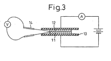
- the contact resistance value was determined as follows. A specimen 11 (20 mm ⁇ 20 mm ⁇ 2 mm) and a carbon plate 12 (1.5 ⁇ 10 -3 ⁇ cm, 20 mm ⁇ 20 mm ⁇ 1 mm) were contacted in an apparatus as shown in Fig. 3 and then the specimen 11 and carbon plate 12 were sandwiched between copper plates 13, and a load of 98N was applied thereon. A constant current of 1 A was passed in the through direction and terminals 14 were contacted to the interface between the specimen 11 and the carbon plate 12 to measure the voltage. From the voltage measured, the resistance value was calculated. The value obtained was integrated with the contacting cross-sectional area and the resulting value was designated as the contact resistance value.
- the heat resistance was measured and compared by the three-stage evaluation such that a bent specimen was left standing at a temperature of 140°C in a Perfect oven (trade name, mfd. by Tabai-Espec K.K.) for 2,000 hours in an air atmosphere and thereafter whether the rate of change in the flexural strength is 20% or less, from 20 to 50%, or 50% or more (three-stage evaluation) was determined.
- a Perfect oven trade name, mfd. by Tabai-Espec K.K.
- the acid resistance was measured and compared by the three-stage evaluation such that a specimen was dipped in an aqueous 5% sulfuric acid solution kept at a temperature of 90°C for 100 hours and thereafter, whether the rate of change in the flexural strength was 20% or less, from 20 to 50%, or 50% or more was determined.
- the spiral flow was determined by forming a sample under a pressure of 10 MPa by using a transfer molding machine 50t and measuring the spiral flow length (temp: 160°C, curing time: 3 min.).
- the resin composition was obtained by blending the components while kneading the components at a temperature of 40°C for 30 minutes by using a universal mixing stirrer having a mechanism such that the stirring blade autorotates and revolves.
- the resin compositions obtained were revealed to have excellent storage stability without undergoing any change in the properties, even after the storage at 23°C for 3 months (humidity: 50%, storage in dark place).
- hydroquinone was added in an amount of 0.05 parts by mass based on the total amount of the resin composition.
- each of the resin compositions obtained was cured by heating the composition at 140°C for 5 minutes under applied pressure (200 kg/cm 2 ) by using a compression molding machine to form a cured product of 100 mm (thickness) ⁇ 100 mm ⁇ 2 mm.
- the cured product was obtained by curing the composition while heating at 180°C for 4 minutes under applied pressure.
- the resin composition was obtained by kneading the components at a temperature of 80°C for 15 minutes by using a kneader.
- the resin compositions obtained each was cured by heating the composition at 180°C for 5 minutes under applied pressure (200 kg/cm 2 ) by using a compression molding machine to obtain a cured product.
- composition ratio (mass ratio) in each of the above-described Examples and Comparative Examples is shown in Tables 4, 6 and 8 and the results in the measurement of physical properties are shown in Tables 5, 7 and 9. Further, the results of the spiral flow performed in Examples 2 and 17 to 20 and Comparative Examples 16 to 18 are shown in Table 10.
- each of the B contents shows a data thereof remaining in the graphite powder after graphitization.
- This B contents were analyzed by means of an ICP-MS (inductively coupled plasma-mass spectrometry) apparatus (trade name: SPQ 9000, mfd. by Seiko-Denshi K.K.). With respect to the details of such a measurement, BROEKAETR J A C, PILGER C, POLLAMANN D, et al.; J. Anal. Chem. VOL. 349, NO. 1/3, p. 20 - 25, 1994; title: The use of plasma atomic spectrometric methods for the analysis of ceramic powders may be referred to.
- ICP-MS inductively coupled plasma-mass spectrometry
- thermolysis analysis In the measurement of the B content, in the present invention, X-ray diffraction, fluorescent X-ray analysis, ICP-MS analysis, thermolysis analysis may be used, as described in the following papers;
- the lattice spacing becomes narrow after the graphitization and the graphite obtained can have a high crystallinity.
- the cured product obtained from the electroconductive curable resin composition by using this graphite has a higher electroconductivity as compared with that in a case where graphite containing no boron is used.
- the graphite used has a large tapping bulk density or a broad particle size distribution and a large particle size, the cured product can have still higher electroconductivity.
- the fluidity is further improved by using a graphite powder having a small aspect ratio.
- a graphite powder having a particle size of 80 ⁇ m or more is present, the fluidity is decreased and formation failure occurs.
- the composition using a novolak-type epoxy resin, a vinyl ester resin or a phenolic resin as the curable resin is improved in the acid resistance and heat resistance.
- a phenolic resin is subjected to the reaction, water is generated in the reaction and a large number of pores are formed in the cured product, and as a result, the gas permeability becomes poorer.
- the electroconductive curable resin composition according to the present invention can provide a cured product having an excellent electroconductivity, a high heat resistance, a good heat-radiating property and superior corrosion resistance. Therefore, the composition according to can be widely applied to the fields of materials in which conventional materials have been difficult to use, for example, various uses and parts such as in the fields of electronics, electric products, machine parts and vehicle parts.
- the composition is useful as a raw material for a separator of fuel cells such as solid polymer-type fuel cell.
Landscapes
- Chemical & Material Sciences (AREA)
- Chemical Kinetics & Catalysis (AREA)
- Physics & Mathematics (AREA)
- Engineering & Computer Science (AREA)
- Manufacturing & Machinery (AREA)
- Sustainable Development (AREA)
- Sustainable Energy (AREA)
- Life Sciences & Earth Sciences (AREA)
- Electrochemistry (AREA)
- General Chemical & Material Sciences (AREA)
- Composite Materials (AREA)
- Dispersion Chemistry (AREA)
- Spectroscopy & Molecular Physics (AREA)
- Health & Medical Sciences (AREA)
- Medicinal Chemistry (AREA)
- Polymers & Plastics (AREA)
- Organic Chemistry (AREA)
- Compositions Of Macromolecular Compounds (AREA)
- Fuel Cell (AREA)
- Conductive Materials (AREA)
- Macromonomer-Based Addition Polymer (AREA)
- Manufacture Of Macromolecular Shaped Articles (AREA)
- Carbon And Carbon Compounds (AREA)
Claims (17)
- Elektrisch leitfähige härtbare Harzzusammensetzung, umfassend:(A) ein Graphitpulver, welches Bor in dem Graphitkristall enthält, und(B) ein härtbares Harz und/oder eine härtbare Harzzusammensetzung in einem Verhältnis von 20 bis 99,9 : 80 bis 0,1, ausgedrückt als Massenverhältnis des Bestandteils (A) zu Bestandteil (B), mit der Maßgabe, daß die Summe der Massenverhältnisse der Bestandteile (A) und (B) 100 ist.
- Elektrisch leitfähige härtbare Harzzusammensetzung, umfassend:(A) ein Graphitpulver, welches Bor in dem Graphitkristall enthält,(B) ein härtbares Harz und/oder eine härtbare Harzzusammensetzung, und(C) eine Gasphasenverfahren-Kohlenstofffaser mit einem Faserdurchmesser von 0,05-10 µm und einer Faserlänge von 1-500 µm und/oder ein Kohlenstoff-Nanoröhrchen mit einem Faserdurchmesser von 0,5-100 µm und einer Faserlänge von 0,01-10 µm.
- Elektrisch leitfähige härtbare Harzzusammensetzung nach Anspruch 2, wobei das Massenverhältnis der Summe des Bestandteils (A) und des Bestandteils (C) zu Bestandteil (B) (A+C : B) 20 bis 99,90 : 80 bis 0,01 beträgt, mit der Maßgabe, daß die Summe der Massenverhältnisse der Bestandteile (A), (B) und (C) 100 beträgt.
- Elektrisch leitfähige härtbare Harzzusammensetzung nach Anspruch 2 oder 3, wobei das Massenverhältnis des Bestandteils (A) zu Bestandteil (C) 60 bis 99,9 : 40 bis 0,1 beträgt, mit der Maßgabe, daß die Summe der Massenverhältnisse der Bestandteile (A) und (C) 100 beträgt.
- Elektrisch leitfähige härtbare Harzzusammensetzung nach einem der Ansprüche 1 bis 4, wobei der spezifische elektrische Widerstand des Pulvers des Bestandteils (A) in der Richtung des rechten Winkels, bezogen auf die Richtung des ausgeübten Drucks, in einem Zustand, bei dem das Graphitpulver als Bestandteil (A) zusammengedrückt wird, so dass eine Schüttdichte des Graphitpulvers von 1,5 g/cm3 bereitgestellt wird, 0,06 Ωcm oder weniger beträgt.
- Elektrisch leitfähige härtbare Harzzusammensetzung nach einem der Ansprüche 1 bis 5, wobei der Bestandteil (A) eine durchschnittliche Teilchengröße von 5 bis 80 µm aufweist.
- Elektrisch leitfähige härtbare Harzzusammensetzung nach einem der Ansprüche 1 bis 6, wobei der Bestandteil (A) ein Graphitpulver mit einem spezifischen Oberflächenbereich von 3 m2/g oder weniger, einem Aspektverhältnis von 6 oder weniger, einer Klopfschüttdichte von 0,8 g/cm3 oder mehr und einem Gitterabstand (Co-Wert) von 6,545 Å oder weniger ist.
- Elektrisch leitfähige härtbare Harzzusammensetzung nach einem der Ansprüche 1 bis 7, wobei der Bestandteil (B) mindestens ein Harz, das aus einem Phenolharz, einem ungesättigten Polyesterharz, einem Epoxyharz, einem Vinylesterharz und einem Allylesterharz ausgewählt ist, sowie einen Härter umfaßt.
- Elektrisch leitfähige härtbare Harzzusammensetzung nach Anspruch 8, wobei der Bestandteil (B) ein Epoxyharz und ein Phenolharz umfaßt.
- Elektrisch leitfähige härtbare Harzzusammensetzung nach Anspruch 9, wobei das Epoxyharz ein Cresol-Novolak-Typ-Epoxyharz umfaßt und das Phenolharz ein Novolak-Typ-Phenolharz umfaßt.
- Elektrisch leitfähige härtbare Harzzusammensetzung nach Anspruch 8, wobei der Bestandteil (B) ein Vinylesterharz und/oder ein Allylesterharz, mindestens ein Monomer, das aus einem Allylestermonomer, Acrylsäureestermonomer, Methacrylsäureestermonomer und Styrolmonomer ausgewählt ist, sowie einen Radikalpolymerisationsinitiator umfaßt.
- Elektrisch leitfähige härtbare Harzzusammensetzung nach Anspruch 11, wobei das Vinylesterharz ein Novolak-Typ-Vinylesterharz ist.
- Elektrisch leitfähige härtbare Harzzusammensetzung nach einem der Ansprüche 1 bis 12, wobei der Bestandteil (A) Graphitpulver ist, das 0,05 bis 5,0 Massen-% Bor enthält.
- Elektrisch leitfähiges gehärtetes Produkt, erhalten durch Härten einer elektrisch leitfähigen härtbaren Harzzusammensetzung nach einem der Ansprüche 1 bis 13, welches eine Volumenresistivität von 2x10⁻² Ωcm oder weniger, einen Kontaktwiderstand von 2x10⁻² Ωcm2 oder weniger und eine Wärmeleitfähigkeit von 1,0 W/m·K oder mehr aufweist.
- Verfahren zur Herstellung eines elektrisch leitfähigen gehärteten Produkts nach Anspruch 14, welches das Ausbilden des gehärteten Produkts durch eines der Verfahren Formpressen, Transferpressen, Spritzgießen und Spritzprägen umfaßt.
- Trennelement für Brennstoffzellen, erhalten durch Härten einer elektrisch leitfähigen härtbaren Harzzusammensetzung nach einem der Ansprüche 1 bis 13, welches eine elektrisch leitfähige härtbare Harzzusammensetzung ist, die 50 bis 95 Massen-% des Bestandteils (A) (oder 50 bis 95 Massen-% der Summe der Bestandteile (A) und des Bestandteils (C), wenn vorhanden) umfaßt, wobei das Trennelement eine Volumenresistivität von 2x10⁻² Ωcm oder weniger, einen Kontaktwiderstand von 2x10⁻² Ωcm2 oder weniger, eine Wärmeleitfähigkeit von 1,0 W/m·K oder mehr und eine Gasdurchlässigkeit von 1x10⁻⁶ cm2/s oder weniger aufweist.
- Verfahren zur Herstellung eines Trennelements für Brennstoffzellen, umfassend das Ausbilden eines Trennelements für Brennstoffzellen durch eines der Verfahren Formpressen, Transferpressen, Spritzgießen und Spritzprägen, wobei das Trennelement durch Härten einer elektrisch leitfähigen härtbaren Harzzusammensetzung nach einem der Ansprüche 1 bis 13 erhalten wird, welches eine elektrisch leitfähige härtbare Harzzusammensetzung ist, die 50 bis 95 Massen-% des Bestandteils (A) (oder 50 bis 95 Massen-% der Summe der Bestandteile (A) und des Bestandteils (C), wenn vorhanden) umfaßt, wobei das Trennelement eine Volumenresistivität von 2x10⁻² Ωcm oder weniger, einen Kontaktwiderstand von 2x10⁻² Ωcm2 oder weniger, eine Wärmeleitfähigkeit von 1,0 W/m·K oder mehr und eine Gasdurchlässigkeit von 1x10⁻⁶ cm2/s oder weniger aufweist.
Applications Claiming Priority (5)
| Application Number | Priority Date | Filing Date | Title |
|---|---|---|---|
| JP2000166965 | 2000-06-05 | ||
| JP2000166965 | 2000-06-05 | ||
| JP2001113764A JP3948217B2 (ja) | 2000-06-05 | 2001-04-12 | 導電性硬化性樹脂組成物、その硬化体、及びその成形体 |
| JP2001113764 | 2001-04-12 | ||
| PCT/JP2001/004751 WO2001095344A1 (en) | 2000-06-05 | 2001-06-05 | Electroconductive curable resin composition, cured product thereof and formed product using the composition |
Publications (2)
| Publication Number | Publication Date |
|---|---|
| EP1226588A1 EP1226588A1 (de) | 2002-07-31 |
| EP1226588B1 true EP1226588B1 (de) | 2004-10-06 |
Family
ID=56290135
Family Applications (1)
| Application Number | Title | Priority Date | Filing Date |
|---|---|---|---|
| EP01934556A Expired - Lifetime EP1226588B1 (de) | 2000-06-05 | 2001-06-05 | Elektrisch leitende härtbare harzzusammensetzung , daraus hergestelltes gehärtetes produkt und unter verwendung der zusammensetzung hergestelltes produkt |
Country Status (9)
| Country | Link |
|---|---|
| US (1) | US6627689B2 (de) |
| EP (1) | EP1226588B1 (de) |
| JP (1) | JP3948217B2 (de) |
| KR (1) | KR100458797B1 (de) |
| CN (1) | CN1225746C (de) |
| AT (1) | ATE279010T1 (de) |
| AU (1) | AU6072201A (de) |
| DE (1) | DE60106192T2 (de) |
| WO (1) | WO2001095344A1 (de) |
Cited By (2)
| Publication number | Priority date | Publication date | Assignee | Title |
|---|---|---|---|---|
| DE102009005629A1 (de) | 2009-01-21 | 2010-07-22 | Technische Universität Bergakademie Freiberg | Kohlenstoffgebundene feuerfeste Formkörper oder Massen mit einer hochfesten Bindephase und Verfahren zu ihrer Herstellung |
| DE102011103116A1 (de) | 2011-06-01 | 2012-12-06 | Technische Universität Bergakademie Freiberg | Kohlenstoffgebundene feuerfeste Formkörper oder Massen mit verbesserten thermomechanischen Eigenschaften |
Families Citing this family (71)
| Publication number | Priority date | Publication date | Assignee | Title |
|---|---|---|---|---|
| JP2002025572A (ja) * | 2000-07-10 | 2002-01-25 | Kureha Chem Ind Co Ltd | 固体高分子型燃料電池用溝付セパレータ |
| US20020086198A1 (en) * | 2000-09-11 | 2002-07-04 | Show A Denko K.K. | Electrically conducting curable composition and cured product thereof |
| TW583246B (en) | 2001-02-05 | 2004-04-11 | Toray Industries | Carbon fiber-enforced resin composition and shaped material |
| JP4810734B2 (ja) * | 2001-02-05 | 2011-11-09 | 東レ株式会社 | 炭素繊維強化樹脂組成物、成形材料およびその成形品 |
| US20020197523A1 (en) * | 2001-06-13 | 2002-12-26 | Matsushita Electric Industrial Co., Ltd | Method of producing fuel cell and fuel cell |
| WO2003014209A1 (en) * | 2001-08-06 | 2003-02-20 | Showa Denko K. K. | Conductive curable resin composition and separator for fuel cell |
| WO2003060209A1 (en) * | 2002-01-11 | 2003-07-24 | The Trustees Of Boston College | Reinforced carbon nanotubes |
| JP3978429B2 (ja) * | 2002-03-18 | 2007-09-19 | Ntn株式会社 | 導電性樹脂成形体 |
| JP2003268249A (ja) * | 2002-03-20 | 2003-09-25 | Showa Denko Kk | 導電性硬化性樹脂組成物、その硬化体およびその製造方法 |
| AU2003209898A1 (en) * | 2002-03-20 | 2003-09-29 | Dupont Canada Inc. | Process for decreasing the resistivity of conductive flow field plates for use in fuel cells |
| US20040051082A1 (en) * | 2002-09-16 | 2004-03-18 | Child Andrew D. | Static dissipative textile and method for producing the same |
| US7320947B2 (en) * | 2002-09-16 | 2008-01-22 | Milliken & Company | Static dissipative textile and method for producing the same |
| JP4243141B2 (ja) | 2002-12-24 | 2009-03-25 | 昭和電工株式会社 | 硬化性組成物、その硬化物およびその成形体 |
| DE60321047D1 (de) * | 2002-12-26 | 2008-06-26 | Showa Denko Kk | Kohlenstoffmaterial zur herstellung von elektrisch leitfähigen materialien sowie deren verwendung |
| JP4342929B2 (ja) * | 2002-12-26 | 2009-10-14 | 昭和電工株式会社 | 導電性組成物用炭素質材料及びその用途 |
| US7858185B2 (en) | 2003-09-08 | 2010-12-28 | Nantero, Inc. | High purity nanotube fabrics and films |
| DE602004002096T2 (de) | 2003-03-10 | 2007-03-15 | Dainippon Ink And Chemicals, Inc. | Leitfähige harzzusammensetzung, herstellungsverfahren dafür und brennstoffzellenseparatoren |
| US7375369B2 (en) * | 2003-09-08 | 2008-05-20 | Nantero, Inc. | Spin-coatable liquid for formation of high purity nanotube films |
| US20050112450A1 (en) * | 2003-09-08 | 2005-05-26 | Intematix Corporation | Low platinum fuel cell catalysts and method for preparing the same |
| US8211593B2 (en) * | 2003-09-08 | 2012-07-03 | Intematix Corporation | Low platinum fuel cells, catalysts, and method for preparing the same |
| US7504051B2 (en) * | 2003-09-08 | 2009-03-17 | Nantero, Inc. | Applicator liquid for use in electronic manufacturing processes |
| US7351444B2 (en) * | 2003-09-08 | 2008-04-01 | Intematix Corporation | Low platinum fuel cell catalysts and method for preparing the same |
| US20050070658A1 (en) * | 2003-09-30 | 2005-03-31 | Soumyadeb Ghosh | Electrically conductive compositions, methods of manufacture thereof and articles derived from such compositions |
| TW200519150A (en) * | 2003-12-05 | 2005-06-16 | Showa Denko Kk | Conductive resin composition and molded product thereof |
| JP5025079B2 (ja) * | 2003-12-05 | 2012-09-12 | 昭和電工株式会社 | 導電性樹脂組成物及びその成形体 |
| WO2005086177A1 (en) * | 2004-03-03 | 2005-09-15 | Showa Denko K.K. | Electroconductive resin composition and molded product thereof |
| KR100819825B1 (ko) * | 2004-05-14 | 2008-04-08 | 쇼와 덴코 가부시키가이샤 | 도전성 구조체, 그 제조방법 및 연료전지용 세퍼레이터 |
| JP4889962B2 (ja) * | 2004-05-14 | 2012-03-07 | 昭和電工株式会社 | 導電性構造体およびその製造方法ならびに燃料電池用セパレータ |
| US7556746B2 (en) * | 2004-06-03 | 2009-07-07 | Nantero, Inc. | Method of making an applicator liquid for electronics fabrication process |
| US7658869B2 (en) * | 2004-06-03 | 2010-02-09 | Nantero, Inc. | Applicator liquid containing ethyl lactate for preparation of nanotube films |
| US20060293434A1 (en) * | 2004-07-07 | 2006-12-28 | The Trustees Of The University Of Pennsylvania | Single wall nanotube composites |
| US7655719B2 (en) * | 2004-07-13 | 2010-02-02 | Cool Options, Inc. | Thermally conductive polymer compositions having moderate tensile and flexural properties |
| JP3776111B1 (ja) * | 2004-08-31 | 2006-05-17 | 株式会社物産ナノテク研究所 | 炭素繊維構造体 |
| JP4507182B2 (ja) * | 2004-10-25 | 2010-07-21 | 昭和高分子株式会社 | 燃料電池用セパレーター |
| TW200623492A (en) * | 2004-11-08 | 2006-07-01 | Tokai Carbon Kk | Separator material for solid polymer fuel cell and process for producing the same |
| KR100577608B1 (ko) * | 2004-11-18 | 2006-05-10 | 한국에너지기술연구원 | 연료전지 세퍼레이터용 성형재료 |
| EP1825038B1 (de) | 2004-12-16 | 2012-09-12 | Nantero, Inc. | Wässrige kohlenstoffnanoröhrchenapplikatorflüssigkeiten und verfahren zur herstellung von applikatorflüssigkeiten daraus |
| JP4854979B2 (ja) * | 2005-03-29 | 2012-01-18 | 新日鐵化学株式会社 | 燃料電池セパレータ用組成物、燃料電池セパレータの製造方法および燃料電池セパレータ |
| US7479654B2 (en) | 2005-05-09 | 2009-01-20 | Nantero, Inc. | Memory arrays using nanotube articles with reprogrammable resistance |
| DE202005014678U1 (de) * | 2005-05-19 | 2006-09-28 | Fraunhofer-Gesellschaft zur Förderung der angewandten Forschung e.V. | Heizelement mit zumindest einem Nanotubes umfasenden Verbundsystem |
| JP2008545839A (ja) * | 2005-05-27 | 2008-12-18 | イー・アイ・デュポン・ドウ・ヌムール・アンド・カンパニー | 低い熱膨張率を有する樹脂組成物およびそれから製造された物品 |
| KR100602512B1 (ko) * | 2005-06-07 | 2006-07-19 | 김성훈 | 탄소나노튜브를 함유하는 방향족 폴리에스테르 나노복합체수지 및 그의 제조방법 |
| US8114314B2 (en) | 2005-07-20 | 2012-02-14 | Agency For Science, Technology And Research | Electroconductive curable resins |
| DE102005049600A1 (de) * | 2005-10-17 | 2007-04-26 | Webasto Ag | Induktivität mit leitfähigem Kunststoff |
| US8421755B2 (en) * | 2006-01-17 | 2013-04-16 | World Properties, Inc. | Capacitive touch sensor with integral EL backlight |
| KR101248161B1 (ko) * | 2006-02-08 | 2013-03-27 | 엘지전자 주식회사 | 열확산층, 이를 포함하는 백라이트 유닛 및 디스플레이장치 |
| KR100801593B1 (ko) * | 2006-02-27 | 2008-02-11 | 제일모직주식회사 | 연료전지용 바이폴라 플레이트 |
| US8129463B2 (en) * | 2006-03-31 | 2012-03-06 | Applied Nanotech Holdings, Inc. | Carbon nanotube-reinforced nanocomposites |
| US20110160346A1 (en) * | 2006-03-31 | 2011-06-30 | Applied Nanotech Holdings, Inc. | Dispersion of carbon nanotubes by microfluidic process |
| US8283403B2 (en) * | 2006-03-31 | 2012-10-09 | Applied Nanotech Holdings, Inc. | Carbon nanotube-reinforced nanocomposites |
| US8445587B2 (en) * | 2006-04-05 | 2013-05-21 | Applied Nanotech Holdings, Inc. | Method for making reinforced polymer matrix composites |
| US7796123B1 (en) * | 2006-06-20 | 2010-09-14 | Eastman Kodak Company | Touchscreen with carbon nanotube conductive layers |
| US8030376B2 (en) | 2006-07-12 | 2011-10-04 | Minusnine Technologies, Inc. | Processes for dispersing substances and preparing composite materials |
| KR100706653B1 (ko) * | 2006-12-27 | 2007-04-13 | 제일모직주식회사 | 열전도성 수지 조성물 및 플라스틱 성형품 |
| US8653177B2 (en) * | 2007-02-28 | 2014-02-18 | Showa Denko K.K. | Semiconductive resin composition |
| DE102008020135A1 (de) * | 2008-04-22 | 2009-10-29 | Bayer Materialscience Ag | Reaktionsharz auf Basis eines ungesättigten Polyesters, radikalisch härtbaren Vinylverbindungen und Kohlenstoffnanoröhrchen |
| KR101855056B1 (ko) * | 2008-08-22 | 2018-05-04 | 히타치가세이가부시끼가이샤 | 감광성 도전 필름, 도전막의 형성 방법, 도전 패턴의 형성 방법 및 도전막 기판 |
| WO2010115085A1 (en) * | 2009-04-03 | 2010-10-07 | Alcoa Inc. | Conductive solid film material |
| JP2011228059A (ja) * | 2010-04-16 | 2011-11-10 | Sumitomo Electric Ind Ltd | レドックスフロー電池用双極板 |
| US20130171547A1 (en) * | 2010-09-10 | 2013-07-04 | Nisshinbo Chemical Inc. | Fuel cell separator |
| WO2012043319A1 (ja) * | 2010-09-27 | 2012-04-05 | パナソニック株式会社 | 燃料電池セパレータ成形用組成物、燃料電池セパレータ、燃料電池セパレータの製造方法、及び燃料電池 |
| US20130309926A1 (en) * | 2011-01-12 | 2013-11-21 | Hodogaya Chemical Co., Ltd. | Thermosetting resin-containing solution in which fine carbon fibers are dispersed and thermosetting resin formed articles thereof |
| CN103379681B (zh) * | 2012-04-28 | 2016-03-30 | 清华大学 | 加热垫 |
| EP3284782B1 (de) | 2013-09-10 | 2022-07-27 | Riken Technos Corporation | Elektrisch leitende harzzusammensetzung und daraus hergestellter film |
| CN103965582B (zh) * | 2014-04-24 | 2016-04-27 | 山东省阳信丰源科技有限公司 | 用于拉挤成型工艺的碳纳米双固化树脂基体及复合材料 |
| JP6453026B2 (ja) | 2014-10-09 | 2019-01-16 | リケンテクノス株式会社 | 熱可塑性樹脂組成物フィルムの製造方法 |
| JP6898543B2 (ja) * | 2016-03-31 | 2021-07-07 | 日本ガスケット株式会社 | 熱伝導性樹脂組成物およびこれを用いた成形品の製造方法 |
| WO2018190364A1 (ja) * | 2017-04-11 | 2018-10-18 | 株式会社大阪ソーダ | ナノ物質含有組成物 |
| JP7059873B2 (ja) * | 2017-12-19 | 2022-04-26 | 東洋インキScホールディングス株式会社 | 導電性組成物、および導電膜 |
| KR102236848B1 (ko) * | 2019-06-13 | 2021-04-07 | 주식회사 포스코 | 도금 강판의 방열성 도료 조성물, 방열성 도금강판 제조방법 및 방열성 도금강판 |
| JP7439401B2 (ja) * | 2019-07-03 | 2024-02-28 | artience株式会社 | 非接触型メディア |
Family Cites Families (2)
| Publication number | Priority date | Publication date | Assignee | Title |
|---|---|---|---|---|
| US4414142A (en) * | 1980-04-18 | 1983-11-08 | Vogel F Lincoln | Organic matrix composites reinforced with intercalated graphite |
| US6150446A (en) * | 1997-08-29 | 2000-11-21 | Teijin Limited | Destaticizing thermoplastic resin composition |
-
2001
- 2001-04-12 JP JP2001113764A patent/JP3948217B2/ja not_active Expired - Lifetime
- 2001-06-05 AU AU60722/01A patent/AU6072201A/en not_active Abandoned
- 2001-06-05 AT AT01934556T patent/ATE279010T1/de not_active IP Right Cessation
- 2001-06-05 DE DE60106192T patent/DE60106192T2/de not_active Expired - Lifetime
- 2001-06-05 KR KR10-2001-7015676A patent/KR100458797B1/ko not_active IP Right Cessation
- 2001-06-05 US US09/890,233 patent/US6627689B2/en not_active Expired - Lifetime
- 2001-06-05 EP EP01934556A patent/EP1226588B1/de not_active Expired - Lifetime
- 2001-06-05 WO PCT/JP2001/004751 patent/WO2001095344A1/en active IP Right Grant
- 2001-06-05 CN CNB018008402A patent/CN1225746C/zh not_active Expired - Lifetime
Cited By (2)
| Publication number | Priority date | Publication date | Assignee | Title |
|---|---|---|---|---|
| DE102009005629A1 (de) | 2009-01-21 | 2010-07-22 | Technische Universität Bergakademie Freiberg | Kohlenstoffgebundene feuerfeste Formkörper oder Massen mit einer hochfesten Bindephase und Verfahren zu ihrer Herstellung |
| DE102011103116A1 (de) | 2011-06-01 | 2012-12-06 | Technische Universität Bergakademie Freiberg | Kohlenstoffgebundene feuerfeste Formkörper oder Massen mit verbesserten thermomechanischen Eigenschaften |
Also Published As
| Publication number | Publication date |
|---|---|
| US6627689B2 (en) | 2003-09-30 |
| KR20020028891A (ko) | 2002-04-17 |
| EP1226588A1 (de) | 2002-07-31 |
| CN1366679A (zh) | 2002-08-28 |
| ATE279010T1 (de) | 2004-10-15 |
| DE60106192T2 (de) | 2005-06-23 |
| JP3948217B2 (ja) | 2007-07-25 |
| CN1225746C (zh) | 2005-11-02 |
| US20030013798A1 (en) | 2003-01-16 |
| JP2002060639A (ja) | 2002-02-26 |
| KR100458797B1 (ko) | 2004-12-03 |
| WO2001095344A1 (en) | 2001-12-13 |
| AU6072201A (en) | 2001-12-17 |
| DE60106192D1 (de) | 2004-11-11 |
Similar Documents
| Publication | Publication Date | Title |
|---|---|---|
| EP1226588B1 (de) | Elektrisch leitende härtbare harzzusammensetzung , daraus hergestelltes gehärtetes produkt und unter verwendung der zusammensetzung hergestelltes produkt | |
| US8747703B2 (en) | Electrically conducting curable resin composition, cured product thereof and method for producing the same | |
| JP3937962B2 (ja) | 導電性硬化性樹脂組成物 | |
| KR100722812B1 (ko) | 도전성 경화성 수지 조성물, 그 경화체 및 그 제조 방법 | |
| US8053501B2 (en) | Curable composition, cured product thereof, molded product thereof and use as fuel cell separator | |
| WO2001092151A1 (fr) | Composite a base de carbone electriquement conducteur a fines particules, catalyseur pour pile a combustible a polymere solide et batterie de piles | |
| JP4883361B2 (ja) | 導電性硬化性樹脂組成物、その硬化体、及びその成形体 | |
| JP4628143B2 (ja) | 導電性樹脂組成物およびその成形体 | |
| JP5207596B2 (ja) | 導電性硬化性樹脂組成物、その硬化体およびその成形体 | |
| JP4937529B2 (ja) | 燃料電池セパレータ用導電性樹脂組成物および燃料電池セパレータ | |
| JP2005209641A (ja) | 燃料電池用セパレータ及びその製造方法 | |
| KR20030036887A (ko) | 도전성 경화성 수지 조성물 및 연료 전지용 세퍼레이터 | |
| JP2005336478A (ja) | 硬化性組成物、その硬化物およびその成形体 | |
| WO2015163253A1 (ja) | カーボン集電体およびそれを備えた燃料電池 | |
| JP2005344110A (ja) | 硬化性組成物、その硬化物およびその成形体 | |
| WO2005086177A1 (en) | Electroconductive resin composition and molded product thereof |
Legal Events
| Date | Code | Title | Description |
|---|---|---|---|
| PUAI | Public reference made under article 153(3) epc to a published international application that has entered the european phase |
Free format text: ORIGINAL CODE: 0009012 |
|
| 17P | Request for examination filed |
Effective date: 20020222 |
|
| AK | Designated contracting states |
Kind code of ref document: A1 Designated state(s): AT BE CH CY DE DK ES FI FR GB GR IE IT LI LU MC NL PT SE TR |
|
| AX | Request for extension of the european patent |
Free format text: AL;LT;LV;MK;RO;SI |
|
| 17Q | First examination report despatched |
Effective date: 20030724 |
|
| GRAP | Despatch of communication of intention to grant a patent |
Free format text: ORIGINAL CODE: EPIDOSNIGR1 |
|
| GRAS | Grant fee paid |
Free format text: ORIGINAL CODE: EPIDOSNIGR3 |
|
| GRAA | (expected) grant |
Free format text: ORIGINAL CODE: 0009210 |
|
| RIN1 | Information on inventor provided before grant (corrected) |
Inventor name: IMAIZUMI, MITSUHIRO Inventor name: IINO, TADASHI |
|
| AK | Designated contracting states |
Kind code of ref document: B1 Designated state(s): AT BE CH CY DE DK ES FI FR GB GR IE IT LI LU MC NL PT SE TR |
|
| PG25 | Lapsed in a contracting state [announced via postgrant information from national office to epo] |
Ref country code: NL Free format text: LAPSE BECAUSE OF FAILURE TO SUBMIT A TRANSLATION OF THE DESCRIPTION OR TO PAY THE FEE WITHIN THE PRESCRIBED TIME-LIMIT Effective date: 20041006 Ref country code: BE Free format text: LAPSE BECAUSE OF FAILURE TO SUBMIT A TRANSLATION OF THE DESCRIPTION OR TO PAY THE FEE WITHIN THE PRESCRIBED TIME-LIMIT Effective date: 20041006 Ref country code: FI Free format text: LAPSE BECAUSE OF FAILURE TO SUBMIT A TRANSLATION OF THE DESCRIPTION OR TO PAY THE FEE WITHIN THE PRESCRIBED TIME-LIMIT Effective date: 20041006 Ref country code: CH Free format text: LAPSE BECAUSE OF FAILURE TO SUBMIT A TRANSLATION OF THE DESCRIPTION OR TO PAY THE FEE WITHIN THE PRESCRIBED TIME-LIMIT Effective date: 20041006 Ref country code: LI Free format text: LAPSE BECAUSE OF FAILURE TO SUBMIT A TRANSLATION OF THE DESCRIPTION OR TO PAY THE FEE WITHIN THE PRESCRIBED TIME-LIMIT Effective date: 20041006 Ref country code: AT Free format text: LAPSE BECAUSE OF FAILURE TO SUBMIT A TRANSLATION OF THE DESCRIPTION OR TO PAY THE FEE WITHIN THE PRESCRIBED TIME-LIMIT Effective date: 20041006 Ref country code: TR Free format text: LAPSE BECAUSE OF FAILURE TO SUBMIT A TRANSLATION OF THE DESCRIPTION OR TO PAY THE FEE WITHIN THE PRESCRIBED TIME-LIMIT Effective date: 20041006 |
|
| REG | Reference to a national code |
Ref country code: GB Ref legal event code: FG4D |
|
| REG | Reference to a national code |
Ref country code: CH Ref legal event code: EP |
|
| REG | Reference to a national code |
Ref country code: IE Ref legal event code: FG4D |
|
| REF | Corresponds to: |
Ref document number: 60106192 Country of ref document: DE Date of ref document: 20041111 Kind code of ref document: P |
|
| PG25 | Lapsed in a contracting state [announced via postgrant information from national office to epo] |
Ref country code: GR Free format text: LAPSE BECAUSE OF FAILURE TO SUBMIT A TRANSLATION OF THE DESCRIPTION OR TO PAY THE FEE WITHIN THE PRESCRIBED TIME-LIMIT Effective date: 20050106 Ref country code: DK Free format text: LAPSE BECAUSE OF FAILURE TO SUBMIT A TRANSLATION OF THE DESCRIPTION OR TO PAY THE FEE WITHIN THE PRESCRIBED TIME-LIMIT Effective date: 20050106 |
|
| REG | Reference to a national code |
Ref country code: SE Ref legal event code: TRGR |
|
| PG25 | Lapsed in a contracting state [announced via postgrant information from national office to epo] |
Ref country code: ES Free format text: LAPSE BECAUSE OF FAILURE TO SUBMIT A TRANSLATION OF THE DESCRIPTION OR TO PAY THE FEE WITHIN THE PRESCRIBED TIME-LIMIT Effective date: 20050117 |
|
| LTIE | Lt: invalidation of european patent or patent extension |
Effective date: 20041006 |
|
| NLV1 | Nl: lapsed or annulled due to failure to fulfill the requirements of art. 29p and 29m of the patents act | ||
| REG | Reference to a national code |
Ref country code: CH Ref legal event code: PL |
|
| PG25 | Lapsed in a contracting state [announced via postgrant information from national office to epo] |
Ref country code: CY Free format text: LAPSE BECAUSE OF FAILURE TO SUBMIT A TRANSLATION OF THE DESCRIPTION OR TO PAY THE FEE WITHIN THE PRESCRIBED TIME-LIMIT Effective date: 20050605 Ref country code: LU Free format text: LAPSE BECAUSE OF NON-PAYMENT OF DUE FEES Effective date: 20050605 |
|
| PG25 | Lapsed in a contracting state [announced via postgrant information from national office to epo] |
Ref country code: IE Free format text: LAPSE BECAUSE OF NON-PAYMENT OF DUE FEES Effective date: 20050606 |
|
| PG25 | Lapsed in a contracting state [announced via postgrant information from national office to epo] |
Ref country code: MC Free format text: LAPSE BECAUSE OF NON-PAYMENT OF DUE FEES Effective date: 20050630 |
|
| PLBE | No opposition filed within time limit |
Free format text: ORIGINAL CODE: 0009261 |
|
| STAA | Information on the status of an ep patent application or granted ep patent |
Free format text: STATUS: NO OPPOSITION FILED WITHIN TIME LIMIT |
|
| ET | Fr: translation filed | ||
| 26N | No opposition filed |
Effective date: 20050707 |
|
| REG | Reference to a national code |
Ref country code: IE Ref legal event code: MM4A |
|
| PG25 | Lapsed in a contracting state [announced via postgrant information from national office to epo] |
Ref country code: PT Free format text: LAPSE BECAUSE OF NON-PAYMENT OF DUE FEES Effective date: 20050306 |
|
| PGFP | Annual fee paid to national office [announced via postgrant information from national office to epo] |
Ref country code: GB Payment date: 20140604 Year of fee payment: 14 |
|
| PGFP | Annual fee paid to national office [announced via postgrant information from national office to epo] |
Ref country code: IT Payment date: 20140616 Year of fee payment: 14 Ref country code: SE Payment date: 20140611 Year of fee payment: 14 |
|
| PGFP | Annual fee paid to national office [announced via postgrant information from national office to epo] |
Ref country code: FR Payment date: 20140609 Year of fee payment: 14 |
|
| PG25 | Lapsed in a contracting state [announced via postgrant information from national office to epo] |
Ref country code: IT Free format text: LAPSE BECAUSE OF NON-PAYMENT OF DUE FEES Effective date: 20150605 |
|
| REG | Reference to a national code |
Ref country code: SE Ref legal event code: EUG |
|
| GBPC | Gb: european patent ceased through non-payment of renewal fee |
Effective date: 20150605 |
|
| PG25 | Lapsed in a contracting state [announced via postgrant information from national office to epo] |
Ref country code: SE Free format text: LAPSE BECAUSE OF NON-PAYMENT OF DUE FEES Effective date: 20150606 |
|
| REG | Reference to a national code |
Ref country code: FR Ref legal event code: ST Effective date: 20160229 |
|
| PG25 | Lapsed in a contracting state [announced via postgrant information from national office to epo] |
Ref country code: GB Free format text: LAPSE BECAUSE OF NON-PAYMENT OF DUE FEES Effective date: 20150605 |
|
| PG25 | Lapsed in a contracting state [announced via postgrant information from national office to epo] |
Ref country code: FR Free format text: LAPSE BECAUSE OF NON-PAYMENT OF DUE FEES Effective date: 20150630 |
|
| PGFP | Annual fee paid to national office [announced via postgrant information from national office to epo] |
Ref country code: DE Payment date: 20200527 Year of fee payment: 20 |
|
| REG | Reference to a national code |
Ref country code: DE Ref legal event code: R071 Ref document number: 60106192 Country of ref document: DE |