EP1222976A2 - Verfahren und Vorrichtung zur Herstellung eines Leichtmetallrades für ein Fahrzeug - Google Patents
Verfahren und Vorrichtung zur Herstellung eines Leichtmetallrades für ein Fahrzeug Download PDFInfo
- Publication number
- EP1222976A2 EP1222976A2 EP02000721A EP02000721A EP1222976A2 EP 1222976 A2 EP1222976 A2 EP 1222976A2 EP 02000721 A EP02000721 A EP 02000721A EP 02000721 A EP02000721 A EP 02000721A EP 1222976 A2 EP1222976 A2 EP 1222976A2
- Authority
- EP
- European Patent Office
- Prior art keywords
- die
- light alloy
- movable platen
- alloy wheel
- wheel
- Prior art date
- Legal status (The legal status is an assumption and is not a legal conclusion. Google has not performed a legal analysis and makes no representation as to the accuracy of the status listed.)
- Withdrawn
Links
Images


Classifications
-
- B—PERFORMING OPERATIONS; TRANSPORTING
- B60—VEHICLES IN GENERAL
- B60B—VEHICLE WHEELS; CASTORS; AXLES FOR WHEELS OR CASTORS; INCREASING WHEEL ADHESION
- B60B3/00—Disc wheels, i.e. wheels with load-supporting disc body
- B60B3/06—Disc wheels, i.e. wheels with load-supporting disc body formed by casting
-
- B—PERFORMING OPERATIONS; TRANSPORTING
- B22—CASTING; POWDER METALLURGY
- B22D—CASTING OF METALS; CASTING OF OTHER SUBSTANCES BY THE SAME PROCESSES OR DEVICES
- B22D15/00—Casting using a mould or core of which a part significant to the process is of high thermal conductivity, e.g. chill casting; Moulds or accessories specially adapted therefor
- B22D15/005—Casting using a mould or core of which a part significant to the process is of high thermal conductivity, e.g. chill casting; Moulds or accessories specially adapted therefor of rolls, wheels or the like
-
- B—PERFORMING OPERATIONS; TRANSPORTING
- B22—CASTING; POWDER METALLURGY
- B22D—CASTING OF METALS; CASTING OF OTHER SUBSTANCES BY THE SAME PROCESSES OR DEVICES
- B22D18/00—Pressure casting; Vacuum casting
- B22D18/04—Low pressure casting, i.e. making use of pressures up to a few bars to fill the mould
-
- B—PERFORMING OPERATIONS; TRANSPORTING
- B60—VEHICLES IN GENERAL
- B60B—VEHICLE WHEELS; CASTORS; AXLES FOR WHEELS OR CASTORS; INCREASING WHEEL ADHESION
- B60B1/00—Spoked wheels; Spokes thereof
- B60B1/06—Wheels with compression spokes
- B60B1/08—Wheels with compression spokes formed by casting
Definitions
- the present invention relates to a die-cast light alloy wheel for a vehicle having thin spoke portions for providing extremely sharp impression, and a method and an apparatus for producing such a wheel.
- Road wheels of automobiles have various shapes, and their materials have been changing from iron to light alloys such as aluminum alloys, magnesium alloys, titanium alloys, etc. for the purpose of reduction of weight and improvement in appearance and design of automobiles.
- iron is a lightweight alloy having relatively low cost
- the percentage of automobiles having aluminum wheels is recently increasing dramatically.
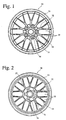
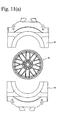
- a light alloy wheel 30 generally consists of a thick hub portion 31 mounted onto an axle with bolts and nuts, a disc portion having a design portion 32 provided with both thick portions and thin portions, and a thin rim portion 33 onto which a tire is mounted.
- the rim portion 33 is constituted by a front flange portion, a rear flange portion, a cross portion in which a rim portion and a disc portion are crossing, and a center rim portion.
- the design portion 32 has spoke portions 34 and design recesses 35.
- the hub portion 31 is provided with bolt hole recesses 36 into which bolts are inserted to fix the wheel to a vehicle body.
- the spoke-type wheel is a wheel designed to have 3-10 spokes extending from the hub portion to the rim portion.
- the dish-type wheel is a wheel having a hub portion having a smoother surface in a considerably wide area than the spoke-type wheel, and a substantially disc-shaped design portion connected to the rim portion with short spokes.
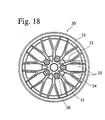
- the fin-type wheel is a wheel having a relatively large number of thin spokes.
- the mesh-type wheel also has a relatively large number of thin spokes, the spokes being in a mesh shape between the hub portion and the rim portion.
- spoke portions extending from a thick hub portion to a rim portion have various shapes, and to impart the impression of speed and functionality, etc. to the overall design of a vehicle, it is desired that the spoke portions have shapes having sharp appearance.
- the spoke portions would not easily be separated from the die, resulting in scratch on the tapered surfaces by their sliding on the die.
- the taper angles of the spoke portions can be made smaller by using such methods as forging, cutting, etc., such methods lead to high production cost.
- the dent portions 37 of the hub portion and the spoke portions should have tapered surfaces 39 having relatively large slanting angles ⁇ '.
- a cast portion 34b having a tapered surface of a slanting angle ⁇ ' remains in an as-die-cast state, in addition to a cast portion 34a having a tapered surface of a slanting angle ⁇ , which is indispensable for strength, and the cast portion 34b should be removed by working later. Accordingly, it is difficult to reduce the weight of a wheel having thin spoke portions.
- an object of the present invention is to provide a light alloy wheel for a vehicle, which has narrow spoke portions with small taper angles, thereby having sharp impression and reduced weight.
- Another object of the present invention is to provide a light alloy wheel for a vehicle, which has spoke portions with small taper angles, whereby it can have reduced weight even if its design portion has various shapes.
- a further object of the present invention is to provide a light alloy wheel for a vehicle, which has spoke portions with small taper angles and dent portions on the rear side, whereby it has high strength free from casting defects even if the spoke portions have small cross sections.
- a still further object of the present invention is to provide a method and an apparatus for producing such a light alloy wheel for a vehicle.
- the inventors have found that by improving the conditions of controlling die-opening operations and elevating a movable platen as die casting conditions for a light alloy wheel for a vehicle, it is possible to obtain a light alloy wheel for a vehicle having sharp impression and reduced weight because of small taper angles in spoke portions.
- the present invention has been completed based on this finding.
- the light alloy wheel for a vehicle comprises a disc portion comprising a hub portion and a design portion and a rim portion, the design portion having substantially as-die-cast spoke portions having at least partially taper angles of less than 5.0°.
- substantially as-die-cast means that no work is done after die casting to such an extent of affecting a taper angle.
- a substantially as-die-cast dent portion having at least partially a taper angle of less than 5.0° is preferably formed on the rear side of each spoke portion.
- the first method for producing a light alloy wheel for a vehicle comprises using a casting apparatus comprising a die assembly comprising at least a stationary lower die and a movable upper die, a movable platen to which the upper die is fixed, and one cylinder mounted onto a frame of the apparatus for moving the movable platen; and driving the cylinder to slowly reduce the clamping force of the lower die and the upper die.
- the reduction of the die-clamping force by the cylinder is preferably carried out by reducing a piston-lowering hydraulic pressure of the cylinder to zero over a time period of 0.05 seconds or more while a constant piston-elevating hydraulic pressure is applied to the cylinder.
- the second method for producing a light alloy wheel for a vehicle comprises using a casting apparatus comprising a die assembly comprising at least a stationary lower die and a movable upper die, a movable platen to which the upper die is fixed, and a first cylinder and at least three synchronous second cylinders both mounted onto a frame of the apparatus for moving the movable platen; synchronously driving the second cylinders to elevate the movable platen in parallel from a position at which the lower die and the upper die are clamped to a position at which the wheel would not impinge on the lower die even if the movable platen were slanted; and then further elevating the movable platen by the first cylinder.
- the third method for producing a light alloy wheel for a vehicle comprises using a casting apparatus comprising a die assembly comprising at least a stationary lower die and a movable upper die, a movable platen to which the upper die is fixed, a first cylinder and at least three synchronous second cylinders mounted onto a frame of the apparatus for moving the movable platen; driving the first cylinder to slowly reduce the clamping force of the lower die and the upper die; synchronously driving the second cylinders to elevate the movable platen in parallel from a position at which the lower die and the upper die are clamped to a position at which the wheel would not impinge on the lower die even if the movable platen were slanted; and then further elevating the movable platen by the first cylinder.
- the reduction of the die-clamping force by the first cylinder is preferably carried out by reducing a piston-lowering hydraulic pressure of the first cylinder to zero over a time period of 0.05 seconds or more while a constant piston-elevating hydraulic pressure is applied to the first cylinder.
- the apparatus for producing a light alloy wheel for a vehicle comprises a die assembly comprising at least a stationary lower die and a movable upper die, a movable platen to which the upper die is fixed, and a vertical movement mechanism of the movable platen mounted onto a frame of the casting apparatus; the vertical movement mechanism comprising (a) a first cylinder for moving the movable platen up and down, and (b) at least three second cylinders synchronously driven for elevating the movable platen in parallel from a position at which the lower die and the upper die are clamped to a position at which the wheel would not impinge on the lower die even if the movable platen were slanted; and the movable platen being elevated by the first cylinder above the upper limit position of the second cylinders.
- the second cylinders are preferably four hydraulic cylinders arranged at symmetric positions of the frame.
- 30% or more, particularly 50% or more, of the tapered surfaces of the spoke portions preferable have taper angles of less than 5.0°. Further, at least part of the taper angles of the spoke portions are preferably 4.0° or less, particularly 3.5° or less.
- the wheel can provide extremely sharp impression.
- the spoke portions can be cast such that a dent portion on the rear side of each spoke portion has a taper angle of less than 5.0°.
- the ceiling thickness of the spoke portion is preferably 5 mm or less.
- At least part of the spoke portions preferably have a DAS value of less than 30 ⁇ m. Also, the maximum DAS value of the rim portion is preferably larger than the DAS value of the hub portion.
- narrower and deeper dent portions can be formed according to the method of the present invention, thin spoke portions not only in the spoke-type wheel but also in the mesh-type or fin-type wheel can be provided with reduced weight.
- Both of the taper angle on a design surface and the taper angle of a dent portion on the rear side can be made 4.5° or less, further 4.0° or less, particularly 3.5° or less.
- the light alloy wheel having such features for a vehicle according to the present invention can be integrally cast by a low-pressure casting method.
- the light alloy wheel for a vehicle according to the present invention comprising a disc portion comprising a hub portion and a design portion and a rim portion is not limited to an integrally die-cast, one-piece wheel, but also includes a two-piece or three-piece wheel comprising a die-cast disc portion bonded to a rim portion produced by a different method.
- the present invention is most effective to cast one-piece, light alloy wheels.
- the spoke portions are a plurality of elongated ridge portions extending between a hub portion and a rim portion of the wheel.
- the taper angle of each spoke portion is an angle of the tapered surface of the spoke portion to a wheel axis direction, which is indicated by ⁇ in Figs. 4-6.
- the taper angle is an angle ⁇ of the tapered surface 40 to the wheel axis direction A, regardless of whether the spoke portion 34 has a flat top surface 41 (Fig. 4) or a curved top surface 41 (Fig. 5) on the side of a design surface.
- the slanting angle of the tapered surface 40 is an angle ⁇ of a portion having the smallest angle to the wheel axis direction A.
- the tapered surface 40 of the spoke portion 34 is formed by a die for forming a front side of the design portion, though it may be formed by a die for forming a rear side. In the latter case, the spoke portion 34 has a reverse taper that is wide on the design surface and becomes narrower toward a deeper side.
- a percentage of the tapered surface having a slanting angle of less than 5° is defined by a ratio (%) of the contour length of the tapered surface having that slanting angle to the contour length of the entire spoke portion.
- each spoke portion does not have a constant width W at a base.
- the minimum value of the width W at a base is defined as a minimum width W min of the spoke portion.
- the spoke portion 34 giving sharp impression preferably has a taper angle of less than 5.0° and a minimum width W min of 5 mm or less.
- the flow of a melt is poor in the spoke portions 34 having small cross sections, resulting in high likelihood of casting defects.
- the spoke portions have taper angles of less than 5.0° and a minimum width W min of 5 mm or less, the flow of a melt is poor in the spoke portions in a side gate method in which a sprue is provided only in a rim portion, or a center gate method in which a sprue is provided only in a disc portion, resulting in poor casting conditions and slow casting cycle.
- the spoke portion 34 can have a minimum width W min of 4 mm or less and a height T 1 of 25 mm or more even with a taper angle of less than 5°.
- the slanting angle of the tapered surface 39 of the dent portion 37 is indicated by ⁇ in Figs. 7 and 8.
- the taper angle ⁇ of the dent portion 37 is an angle of the tapered surface 39 to a wheel axis direction A.
- the taper angle ⁇ of the dent portion 37 is an angle of a portion having the minimum angle to the wheel axis direction A.
- the spoke portion 34 can have a minimum width W min of 4.5 mm or less, a height T 1 of 30 mm or more, and a ceiling thickness T 2 of 5 mm or less, preferably 4 mm or less.
- a parallel-controlled driving apparatus such as hydraulic pressure cylinders for synchronously pushing the movable platen 14 up at three or more symmetric points to open a lower die 8 or an upper die 12 forming the disc portion from the other die.
- the upper plate 17 is elevated in parallel by four synchronous cylinders 21 fixed to the upper platen 13 from the lowermost position [Fig. 10(b)] to a position P 2 as high as about 20-30 mm therefrom [Fig. 10(c)].
- 3 or more synchronous cylinders may be mounted onto the lower platen 3 to directly elevate the movable platen 14 in parallel. With 2 or less synchronous cylinders, the movable platen 14 is likely to be slanted, making it difficult to cast wheels with small taper angles.
- the movable platen 14 may be slanted during elevation because of this clearance if there is vibration in the casting apparatus.
- the spoke portions and the hub portion having tapered surfaces with slanting angles of 6.0-8.0°, the cast wheel can be separated from the die without deterioration of its appearance even if the movable platen 14 is slanted.
- scratch is likely to be caused in the spoke portions and the hub portion.
- the upper die 12 pushes the lower die 8 at a die-clamping force of about 200 KN.
- This die-clamping force corresponds to a piston-lowering hydraulic pressure of the first hydraulic cylinder 20 of about 10 MPa.
- the piston-lowering hydraulic pressure is reduced from 10 MPa to 0 MPa in less than 0.01 seconds, the strain of the casting apparatus by stress is instantaneously liberated, thereby generating surge pressure in a hydraulic pressure circuit.
- the entire casting apparatus is vibrated, failing to elevate the movable platen 14 in parallel to the lower die 8 without synchronous hydraulic cylinders, and causing the upper die 12 to deviate in a transverse direction, resulting in scratch on the design surface by the lower die 8.
- a hydraulic cylinder is driven by a hydraulic pressure for elevating a piston and a hydraulic pressure for lowering a piston.
- a piston-lowering hydraulic pressure decreases while applying a constant piston-elevating hydraulic pressure to reduce a die-clamping force to zero to open a die assembly.
- a time period in which a valve for a piston-lowering hydraulic pressure is fully opened is about 0.02 seconds, it takes about two times or more until the piston-lowering hydraulic pressure becomes 0 MPa.
- a die-clamping force is preferably elevated slowly, so that vibration and stress exceeding the permitted levels are not applied at the time of die clamping. Rapid die clamping generates vibration in the overall casting apparatus. Because the total weight of the movable platen 14, the lower die 8, etc. is 3-4 tons, strain of about 1 mm is caused by stress in the upper platen 13 and the lower platen 3 in a vertical direction. Also, because the die clamping has influence in a parallel direction, the die clamping is preferably carried out at such a speed as not to generate strain in the production of an aluminum wheel having spoke portions with small taper angles. For this purpose, too, a hydraulic flow-proportional control valve and an electromagnetic valve are preferably used.
- the cast wheel is as hot as 400-450°C with small strength. Particularly when it has a design surface having a complicated shape, it is not easily separated from the lower die 8, and it has weak strength in a separating direction. Unless the cast wheel is elevated smoothly in a vertical direction, its design portion is scratched. Therefore, the control of the elevation of the movable platen 14 fixed to the upper die 12 is extremely important.
- the distance in which the upper die 12 should be elevated completely in parallel to the lower die 8 is about 5-20 mm from the die-clamping position. Above it, the design surface of a wheel would not impinge on the lower die 8 even if the movable platen 14 were slanted to some extent.
- the upper die 12 or the movable platen 14 fixed to the upper die 12 is elevated in parallel synchronously at 3 or more points. For this purpose, it is effective to use four synchronous vertical cylinders arranged symmetrically. An electric current control valve and a servo valve may be used to drive the synchronous cylinders.
- the elevating speed of the movable platen 14 is 10 mm/second or less from the die-clamping position to a height of 5 mm or more, preferably 10 mm or more. Because the design surface of the wheel is in full contact with the lower die 8 at the die-clamping position, the slightest vibration would cause scratch on the design surface. Though there would be no problem with scratch if the entire design surface were worked after casting. However, if wheels are used with as-cast design surfaces, the slightest scratch would make such wheels defective products.
- the spoke portions have small taper angles, this problem is serious.
- the elevating speed of the movable platen 14 is preferably smaller.
- the elevating speed of the movable platen 14 is preferably changeable depending on the elevation distance thereof.
- a wheel can be cast such that it has spoke portions, at least part of which have a DAS (dendrite arm spacing) value of less than 30 ⁇ m. Because dendrite grows to have secondary arms on both sides of its stem in aluminum alloys, the DAS value can be determined by measuring distances between the secondary arms.
- DAS dendrite arm spacing
- the DAS value is less than 30 ⁇ m means that a melt was cooled rapidly in the spoke portions, resulting in a wheel with few casting defects. This makes it possible to apply coating technologies such as vapor deposition and plating. When the DAS value is large, fine pores are generated on the surfaces of spoke portions in vapor deposition and plating due to casting defects, resulting in poor wheel appearance.
- the DAS value is also a measure of the strength of aluminum castings, indicating that the smaller the DAS value, the higher the strength of aluminum castings.
- the DAS value can be less than 30 ⁇ m.
- the spoke portions have a small DAS value, because the spoke portions have small cross sections with taper angles of less than 5°. Because the spoke portions are narrow and small in cross section, the cooling speed of the spoke portions are high. Accordingly, it is possible to obtain an integral cast wheel having thin, high-strength spokes.
- a die portion corresponding to the hub portion is provided with a cooling structure, resulting in a remarkably smaller DAS value in the hub portion than those conventional. Because a melt temperature is high near a center gate, a die-parting coat easily peels off, resulting in likelihood of galling by the melt. Galling by the melt can drastically be suppressed by cooling the die portion corresponding to the hub portion, accompanied by improvement in the strength of the hub portion.
- a light alloy wheel can be obtained with spoke portions having at least partially taper angles of less than 5.0° and with a DAS value in the hub portion smaller than the maximum DAS value in the rim portion.
- the resultant light alloy wheel has dent portions at least partially having taper angles of less than 5.0°. Incidentally, because there is a sprue in the hub portion, the DAS value of the hub portion is measured after finish working.
- a cooling mechanism can be provided in the hub portion without generating casting defects, thereby making a casting cycle shorter and improving the strength of the hub portion in good balance.
- the hub portion is fixed to a vehicle body with bolts, needing enough strength. Because of a high cooling speed, the hub portion can be provided with sufficient strength, so that it can be thin and have reduced weight.
- the light alloy wheel for a vehicle having the above features according to the present invention may be formed by casting not only aluminum alloys but also magnesium alloys, etc.
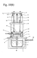
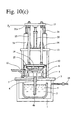
- FIGs. 10(a) -(c) schematically show an apparatus for integrally casting a wheel made of an aluminum alloy as a light alloy wheel for a vehicle of the present invention by a low-pressure casting method.
- a closed container 1 includes a melt-holding furnace 2, and a lower platen 3 arranged above the closed container 1 seals the closed container 1.
- Mounted onto the lower platen 3 at its center is a stoke 4b for supplying an aluminum alloy melt 5 to a stationary lower die 8, with an lower end of the stoke 4b immersed in the melt 5 in the melt-holding furnace 2.
- the stoke 4b extends through the lower platen 3 and a sprue bush 6 inserted into the lower die 8, with an upper end of the stoke 4b connected to a sprue 7 in the lower die 8.
- the melt in the melt-holding furnace 2 flows through the stoke 4b into a cavity of the lower die 8 for forming a wheel at a position corresponding to a hub portion.
- the stationary lower die 8 has a surface for forming a design portion of the wheel.
- the minimum slanting angle of a tapered surface was 3.5°, with a dent portion on the rear side of the spoke portion as shown in Fig. 7.
- a height T 1 was 30 mm
- a minimum width W min was 40 mm
- a ceiling thickness T 2 was 10 mm.
- a pair of transversely movable dies 10, 10 combined with the lower die 8 form a peripheral surface of a rim portion of the wheel.
- the movable upper die 12 mounted onto the movable platen 14 forms a rear surface of the wheel and an inner surface of the rim portion.
- the movable platen 14 is fixed to two guide posts 15, which are movable up and down along guides 16 mounted onto the upper platen 13.
- An upper plate 17 is fixed to upper ends of the guide posts 15, and movable up and down by a first hydraulic cylinder 20 mounted onto the upper platen 13, whereby the movable platen 14 and the upper die 12 are movable up and down.
- Fig. 10(b) shows a state where the upper plate 17 has reached the lowermost position P 1 .
- This lowermost position P 1 is a position at which the upper die 12 is clamped to the transversely movable dies 10 and the lower die 8.
- the four second hydraulic cylinders 21 are synchronously driven, such that upper ends of their pistons 21a are movable from a die-clamping position P 1 to a position P 2 at which the wheel would not impinge on the lower die 8 even if the movable platen 14 were slanted.
- the movable platen 14 With the synchronous elevation of the four second hydraulic cylinders 21 between the position P 1 and the position P 2 , the movable platen 14 is elevated sufficiently in parallel.
- the first hydraulic cylinder 20 is in a neutral state. After the pistons 21a has reached the position P 2 , the first hydraulic cylinder 20 is driven to elevate the upper plate 17 to the uppermost end.
- the casting of a wheel was carried out by the following procedures.
- the piston-lowering hydraulic pressure of the first hydraulic cylinder 20 was slowly reduced without using the second hydraulic cylinders 21, to prevent vibration from occurring in the casting apparatus.
- the first hydraulic cylinder 20 was lowered to cause the upper die 12 to come into contact with the lower die 8 and the transversely movable dies 10, so that the die assembly was clamped at a pressure of 10 MPa.
- a compressed gas such as the air, an inert gas, etc. at 0.02-0.05 MPa was introduced into the closed container 1 through a pipe 18.
- the melt 5 of aluminum (AC4CH) kept at about 700°C in the melt-holding furnace 2 was lifted in the stoke 4b, so that it entered into the cavity of the die assembly kept at 350-450°C.
- An inner surface of the cavity was covered with a temperature-keeping, die-parting coating material.
- the compressed air was evacuated, and an unsolidified melt 5 in the stoke 4 was returned to the melt-holding furnace 2.
- the clamping force of the die assembly was reduced to 0 MPa.
- the upper die 12 was elevated as it was.
- the piston-lowering hydraulic pressure of the first hydraulic cylinder 20 from 10 MPa to 0 MPa in 0.1 seconds while keeping the piston-elevating hydraulic pressure of the first hydraulic cylinder 20 as constant as 2.5 MPa
- the upper die 12 was slowly elevated.
- the cast wheel 25 was removed from the upper die 12 by pushing pins (not shown) fixed to the upper platen 13, and received on a withdrawal member 11 rotated to a position just thereunder [Fig. 10(a)]. This cycle was repeated to continuously cast a large number of aluminum wheels.
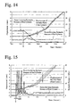
- Fig. 14 shows the variations of the piston-lowering hydraulic pressure and the piston-elevating hydraulic pressure and the displacement of the movable platen 14, when the piston-lowering hydraulic pressure of the first hydraulic cylinder 20 was reduced from 10 MPa to 0 MPa in 0.1 seconds to lower the movable platen 14.
- rightward elevating lines indicate the displacement of the movable platen 14 from the die-clamping position.
- the displacement of the movable platen 14 (1,780 mm x 1,020 mm) was measured at four comers. With reflection-type lasers attached to the movable platen 14 at four comers in the casting apparatus shown in Fig.
- the piston-lowering hydraulic pressure of the first cylinder 20 decreased slowly in 0.1 seconds, without causing vibration in the casting apparatus.
- the movable platen 14 was elevated at a speed of 3 mm/second from the die-clamping position P 1 to a position P 2 of 5 mm.
- Aluminum wheels were cast in the same manner as in EXAMPLE 1 except for using a casting apparatus having a plurality of stokes 4a, 4c as shown in Fig. 12.
- a melt 5 flew through a lower die 8 into transversely movable dies 10, in which it flew into a cavity for forming a rim portion of a wheel.
- the melt 5 was caused to flow at some angle to the wheel axis direction of the cavity, such that the melt 5 entering through the stokes 4a, 4c easily flew in a peripheral direction of the rim.
- 20 aluminum wheels were cast to observe whether or not there were scratch and deformation on their design surfaces. As a result, neither scratch nor deformation was observed on the design surfaces, confirming that every wheel was in a good shape.
- Aluminum wheels each having a design surface shown in Fig. 1 was produced in the same manner as in EXAMPLE 1 except for using a casting apparatus having three stokes as shown in Fig. 13.
- One stoke was positioned such that a melt was injected into a cavity for forming a hub portion of a wheel as in EXAMPLE 1, and the remaining two stokes were positioned such that a melt flew into transversely movable dies 10 and then into a cavity for forming a rim portion of a wheel as in EXAMPLE 2.
- the shape of the lower die 8 was changed to have a taper angle ⁇ of 3.5°, thereby providing each spoke portion with a cross section shape shown in Fig. 4.
- a height T 1 was 30 mm
- a minimum width W min was 40 mm
- 50% or more of a taper angle of the spoke portion was 3.5°.
- Casting was carried out using a casting apparatus having three stokes as in EXAMPLE 3.
- the shapes of the lower die 8 and the upper die 12 were changed to provide each spoke portion with a cross section shape shown in Fig. 7.
- a taper angle ⁇ on a design surface was 3.5°
- a taper angle ⁇ of the dent portion 37 on the rear side of the spoke portion was 5°.
- Each spoke portion had a height T 1 of 30 mm (substantially equal to a height of a tapered surface), a ceiling thickness T 2 of 5 mm, and a minimum width W min of 4.5 mm, the taper angle ⁇ of the spoke portion being 3.5° in a 50% or more region of the spoke portion.
- 20 aluminum wheels were produced. As a result, neither scratch nor deformation was observed on the design surfaces of the resultant aluminum wheels, confirming that every wheel was in a good shape.
- Fig. 15 shows the variations of the piston-lowering hydraulic pressure and the piston-elevating hydraulic pressure and the displacement of the movable platen 14 in this case.
- Other casting conditions and measurement method were identical to those of EXAMPLE 1.
- the piston-lowering hydraulic pressure of the first hydraulic cylinder 20 for lowering the movable platen 14 rapidly decreased, followed by large variations about 5 times. The variations disappeared after about 0.1 seconds from the start of reduction of the piston-lowering hydraulic pressure. It was found that because of these large variations the movable platen 14 was slanted, and that it was elevated while being slanted relative to the lower die 8. It was confirmed that the maximum displacement of the movable platen 14 at each corner took place at a position of about 3-5 mm elevation, with the maximum displacement difference of about 1.5 mm.
- All of 20 aluminum wheels thus cast to have the same shape as in EXAMPLE 1 suffered from scratch and deformation more or less on the design surface.
- the piston-lowering hydraulic pressure of the first hydraulic cylinder 20 was first reduced from 10 MPa to 0 MPa in 0.01 seconds as in COMPARATIVE EXAMPLE 1, and the second hydraulic cylinders 21 were then synchronously driven to elevate the upper plate 17 in parallel from the lowermost position P 1 to a position P 2 as high as about 20-30 mm therefrom. Also, with guide pins of 20 mm in height provided between the upper die 12 and the lower die 8, both dies 8, 12 were prevented from moving in a relatively horizontal direction.
- Aluminum wheels were cast in the same manner as in EXAMPLE 3 except for using a lower die 8 having a hub portion provided with bolt hole recesses 36 each having a taper angle of 4° and depth of 20 mm. As a result, no scratch was observed in the bolt hole recesses, providing wheels with good cast surface.
- Casting was carried out using a die having dent portions having taper angles ⁇ of 3.5° and spoke portions with a cross section shape shown in Fig. 8 in the casting apparatus shown in Fig. 13.
- the tapered surfaces of the spoke portions had a height T 1 of 30 mm or more, a ceiling thickness T 2 of 5 mm or less, and a minimum width W min of 4.5 mm or less, 50% or more of the taper angles ⁇ of the tapered surfaces in the dent portions being 3.5°.
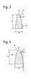
- Fig. 2 shows a rear surface of the wheel. Neither scratch nor deformation was observed on the design surfaces of the resultant aluminum wheels, confirming that every wheel was in a good shape.
- spoke-type aluminum wheels were produced by a low-pressure casting method using a casting apparatus having three stokes as in EXAMPLE 7 and a lower die 8 and an upper die 12 with changed shapes, under the same casting conditions as in EXAMPLE 1 except that dent portions on the rear side of a hub portion had taper angles of 3.5°.
- Fig. 3 shows the rear surface of the wheel. Neither scratch nor deformation was observed on the design surfaces of the resultant aluminum wheels, confirming that every wheel was in a good shape.
- the cooling of a die was investigated in the casting apparatus having three stokes in EXAMPLE 3.
- One stoke was positioned such that a melt was injected into a cavity for forming a hub portion of a wheel as in EXAMPLE 1, and the remaining two stokes were positioned such that a melt was injected into transversely movable dies 10 and then into a cavity for forming a rim portion of a wheel as in EXAMPLE 2.
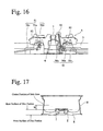
- Fig. 16 shows the details of the lower die 8.
- a plurality of water-cooling mechanisms 50 and a water-cooling mechanism 51 are provided in the lower die 8.
- Each water-cooling mechanism 50 is arranged with its end directed to each die projection 81 for forming each bolt hole recess on a disc surface of a wheel, so that it cools mostly the hub portion.
- Each die projection 81 has a taper angle of about 3.0-10.0°. Cooling water flows into a cooling pipe 50a toward each die projection 81 through a pipe 50b.
- the cooling pipe 50a has a double pipe structure, in which a water flow direction in an inner pipe is opposite to that between an outer pipe and an inner pipe. Cooling water reached to a tip end of each die projection 81 through the inner pipe returns to a pipe 50c.
- the cooling mechanism 51 for cooling a disc portion is constituted by a cooling water path comprising a groove 51b substantially annular about a wheel axis near a portion 82 for forming spoke portions of a wheel in a lower portion of the lower die 8, and a member 51a for sealing the groove 51b. Water flowing into this cooling water path from a pipe 51c cools a die portion 82 corresponding to the spoke portions.
- a temperature of 450° or higher in a cavity surface in die recesses causes the peeling of a die-parting coat, resulting in reaction of the melt with the die, leading to galling. Accordingly, cooling conditions are determined such that the highest temperature on the cavity surface is lower than the galling temperature.
- the wheel cast by the above method has an extremely small DAS value in center portions of the spoke portions.
- Fig. 17 shows the cross section shape of the wheel after working.
- Table 1 shows the DAS values in portions I-IV shown in Fig. 17.
- All wheels of EXAMPLES 3 and 5 produced by using this lower die 8 had DAS values of less than 30 ⁇ m in center portions of the spoke portions. It was also confirmed that the DAS values in center portions of the spoke portions and a hub portion were extremely small, and that they were smaller than the DAS value in a center portion of the rim portion. Though the DAS values in Table 1 are measurement results at side gate positions, the same tendency was also appreciated in the DAS values at positions deviated 90° therefrom.
- Table 1 also shows the DAS values of a wheel produced by a center gate method. Measurement Position DAS value ( ⁇ m) Portion I Hub Portion Portion II Spoke Portion on Hub Side Portion III At Center of Spoke Portion Portion IV At Center of Rim Portion EXAMPLE 3 30 27 25 50 EXAMPLE 5 30 28 25 50 REFERENCE EXAMPLE 2 30 35 25 50 Center Gate Method 40 40 37 34
- Aluminum wheels were produced in the same manner as in EXAMPLE 9 except for using a lower die 8 in which each bolt hole recess 36 in a hub portion had a taper angle of 4° and depth of 20 mm. As a result, wheels free from scratch in the recesses 36 and having good cast surfaces were obtained.
- the first hydraulic cylinder 20 was lowered to cause the upper die 12 to come into contact with the lower die 8 and the transversely movable dies 10, so that the die assembly was clamped at a pressure of 10 MPa.
- a compressed gas such as the air, an inert gas, etc. at 0.02-0.05 MPa was introduced into the closed container 1 through a pipe 18.
- the melt 5 of aluminum (AC4CH) kept at about 700°C in the melt-holding furnace 2 was lifted in the stoke 4b, so that it entered into the cavity of the die assembly kept at 350-450°C.
- An inner surface of the cavity was covered with a temperature-keeping, die-parting coating material.
- the compressed air was evacuated, and an unsolidified melt 5 in the stoke 4 was returned to the melt-holding furnace 2.
- the clamping force of the die assembly was reduced to 0 MPa.
- the upper die 12 was elevated as it was.
- the elevation of the upper die 12 was carried out by synchronously driving four second hydraulic cylinders 21. As shown in Fig. 10(c), after the piston 21a reached a position P 2 , the first hydraulic cylinder 20 was driven to fully elevate the upper die 12. At a time when the upper die 12 was sufficiently elevated, the cast wheel 25 was removed from the upper die 12 by pushing pins (not shown) fixed to the upper platen 13, and received on a withdrawal member 11 rotated to a position just thereunder [Fig. 10(a)]. This cycle was repeated to continuously cast a large number of aluminum wheels.
- the light alloy wheel for a vehicle of the present invention has an as-cast design surface with spoke portions of small taper angles. Also, the light alloy wheel for a vehicle of the present invention has spoke portions providing thinner impression than those conventional without working their tapered surfaces. Even when the wheel has dent portions, as-cast spoke portions have small taper angles.
- the light alloy wheel having the above features for a vehicle according to the present invention has a substantially as-cast design surface, it has not only excellent design but also is light in weight and low in cost.
Landscapes
- Engineering & Computer Science (AREA)
- Mechanical Engineering (AREA)
- Molds, Cores, And Manufacturing Methods Thereof (AREA)
Applications Claiming Priority (2)
| Application Number | Priority Date | Filing Date | Title |
|---|---|---|---|
| JP2001003859A JP2002205501A (ja) | 2001-01-11 | 2001-01-11 | 車両用軽合金ホイール |
| JP2001003859 | 2001-01-11 |
Publications (2)
| Publication Number | Publication Date |
|---|---|
| EP1222976A2 true EP1222976A2 (de) | 2002-07-17 |
| EP1222976A3 EP1222976A3 (de) | 2004-02-04 |
Family
ID=18872141
Family Applications (1)
| Application Number | Title | Priority Date | Filing Date |
|---|---|---|---|
| EP02000721A Withdrawn EP1222976A3 (de) | 2001-01-11 | 2002-01-11 | Verfahren und Vorrichtung zur Herstellung eines Leichtmetallrades für ein Fahrzeug |
Country Status (4)
| Country | Link |
|---|---|
| US (1) | US6837549B2 (de) |
| EP (1) | EP1222976A3 (de) |
| JP (1) | JP2002205501A (de) |
| CN (1) | CN1268504C (de) |
Cited By (2)
| Publication number | Priority date | Publication date | Assignee | Title |
|---|---|---|---|---|
| CN114228390A (zh) * | 2021-12-29 | 2022-03-25 | 长葛市烁宇机械有限公司 | 一种耐用性高的轻量化轮毂 |
| EP4052922A1 (de) * | 2021-03-02 | 2022-09-07 | Yamaha Hatsudoki Kabushiki Kaisha | Gegossenes rad für ein grätschsitzfahrzeug und verfahren zur herstellung davon |
Families Citing this family (33)
| Publication number | Priority date | Publication date | Assignee | Title |
|---|---|---|---|---|
| IT1349275B1 (it) * | 2003-11-28 | 2008-11-20 | Imt Intermato S P A | Metodo e sistema per la produzione di ruote in lega per autoveicoli. |
| USD521032S1 (en) * | 2004-11-17 | 2006-05-16 | Seikoh Giken Co., Ltd. | Sprue bush for a disc-molding die |
| US20070034173A1 (en) * | 2005-08-09 | 2007-02-15 | Lee Chang C | Upright heat dispensing fins of cylinder body |
| CN101554658B (zh) * | 2008-04-09 | 2010-12-08 | 浙江万丰科技开发有限公司 | 一种重力铸造中心浇铸的补缩工艺 |
| USD608711S1 (en) * | 2008-04-14 | 2010-01-26 | Bayerische Motoren Werke Aktiengesellschaft | Wheel or wheel cover |
| US20120200144A1 (en) * | 2011-02-04 | 2012-08-09 | Hodges Francisco J | Brilliant Etched Wheels |
| FR2981605B1 (fr) * | 2011-10-25 | 2013-11-01 | Saint Jean Ind | Procede de fabrication d'une roue hybride en deux parties en alliage leger notamment aluminium |
| JP5903367B2 (ja) * | 2012-11-06 | 2016-04-13 | 本田技研工業株式会社 | 自動二輪車用ホイール |
| JP6384763B2 (ja) * | 2013-07-31 | 2018-09-05 | 日立金属株式会社 | アルミニウム合金製ロードホイールおよびその製造方法 |
| US9815323B2 (en) * | 2014-07-24 | 2017-11-14 | Superior Industries International, Inc. | Cast aluminum wheel |
| US9375976B1 (en) | 2015-03-20 | 2016-06-28 | Honda Motor Co., Ltd. | Wheel with Y-shaped spoke configuration |
| CN106294889B (zh) * | 2015-05-11 | 2019-03-26 | 上海梅山钢铁股份有限公司 | 一种高强钢轮辐中心孔翻边冲模锥角角度优化方法 |
| CN105149551B (zh) * | 2015-10-12 | 2017-12-12 | 浙江今飞凯达轮毂股份有限公司 | 低压铸造模具及铸造轮毂的方法 |
| CN105834400A (zh) * | 2016-05-03 | 2016-08-10 | 刘加兴 | 一种上浇注低压铸造摩托车铝轮的模具结构及其生产工艺 |
| AT518908B1 (de) * | 2016-08-11 | 2019-04-15 | Tyrolit Schleifmittelwerke Swarovski Kg | Trägerkörper für Schleifwerkzeuge |
| USD831555S1 (en) * | 2016-09-02 | 2018-10-23 | Wah Hung Group P.C. | Automobile wheel |
| USD830933S1 (en) * | 2016-09-02 | 2018-10-16 | Wah Hung Group Inc. | Automobile wheel |
| USD824833S1 (en) * | 2017-04-14 | 2018-08-07 | NewCon, LLC | Vehicle wheel |
| USD842796S1 (en) * | 2017-06-21 | 2019-03-12 | Bayerische Motoren Werke Aktiengesellschaft | Vehicle wheel, toy vehicle wheel, and/or replicas thereof |
| JP6932052B2 (ja) * | 2017-09-15 | 2021-09-08 | 川崎重工業株式会社 | 自動二輪車のホイール |
| USD959348S1 (en) * | 2019-02-04 | 2022-08-02 | Wheel Group Holdings, LLC | Wheel front face |
| USD906215S1 (en) * | 2019-03-07 | 2020-12-29 | Daimler Ag | Wheel or wheel cover |
| US11633976B2 (en) | 2019-04-30 | 2023-04-25 | Honda Motor Co., Ltd. | Vehicular wheel having a spoke defining a hollow chamber and vehicles including same |
| USD892017S1 (en) * | 2019-05-13 | 2020-08-04 | Donnie Han | Automotive wheel |
| USD889364S1 (en) * | 2019-05-13 | 2020-07-07 | Donnie Han | Automotive wheel |
| USD942345S1 (en) * | 2019-08-05 | 2022-02-01 | Angela Lee | Automotive wheel |
| DE102020100699A1 (de) * | 2020-01-14 | 2021-07-15 | Audi Aktiengesellschaft | Verfahren zum Herstellen einer Kraftwagenfelge aus Aluminium oder einer Aluminiumlegierung für ein Rad eines Kraftfahrzeugs sowie entsprechende Kraftwagenfelge |
| IT202000017878A1 (it) * | 2020-07-23 | 2022-01-23 | Ferrari Spa | Cerchio per una ruota di un veicolo |
| TR202012231A2 (tr) * | 2020-08-04 | 2020-10-21 | Cms Jant Ve Makina Sanayii Anonim Sirketi | Aksesuarli alümi̇nyum jantlar i̇çi̇n montaj deli̇ği̇ üreti̇m yöntemi̇ |
| USD938336S1 (en) * | 2020-09-30 | 2021-12-14 | Wheel Group Holdings, LLC | Wheel front face |
| CN112387957A (zh) * | 2020-11-17 | 2021-02-23 | 潘毅冰 | 一种用于铝合金汽车轮毂生产的清洁型铸造装置 |
| USD988944S1 (en) * | 2021-06-21 | 2023-06-13 | Audi Ag | Radiator grille for vehicle |
| CN114260438B (zh) * | 2021-12-25 | 2023-11-07 | 云南富源今飞轮毂制造有限公司 | 一种卡车轮毂安装盘螺栓孔强化铸造模具装置及铸造方法 |
Family Cites Families (20)
| Publication number | Priority date | Publication date | Assignee | Title |
|---|---|---|---|---|
| FR547437A (de) * | 1922-12-12 | |||
| US1346863A (en) * | 1919-05-19 | 1920-07-20 | Dayton Steel Foundry Co | Wheel |
| US1414662A (en) * | 1921-06-22 | 1922-05-02 | Morgan William Henry | Cast metal wheel |
| US1502759A (en) * | 1921-10-07 | 1924-07-29 | Jefferson Forge Products Compa | Metal wheel |
| US1685130A (en) * | 1926-10-05 | 1928-09-25 | Nat Malleable & Steel Castings | Vehicle wheel structure |
| US1964129A (en) * | 1931-01-05 | 1934-06-26 | Philip M Miller | Cast wheel |
| US1991489A (en) * | 1931-08-10 | 1935-02-19 | Kelsey Hayes Wheel Corp | Wheel |
| US4165131A (en) * | 1975-11-05 | 1979-08-21 | Gkn Kent Alloys Limited | Cast vehicle wheels |
| CA1220608A (en) | 1984-02-02 | 1987-04-21 | Dbm Industries Limited | Die casting mold |
| DE3763015D1 (de) | 1986-03-03 | 1990-07-12 | Ube Industries | Vertikale spritzgussmaschine. |
| US4840557A (en) | 1986-12-01 | 1989-06-20 | Ube Industries, Ltd. | Vertical injection apparatus |
| JP2817925B2 (ja) | 1988-11-29 | 1998-10-30 | 旭テック 株式会社 | アルミニウム合金製車両用ホイール |
| EP0356736B1 (de) * | 1988-07-31 | 1996-11-06 | Asahi Tec Corporation | Giessanordnung, Verfahren zur Benutzung der Anordnung, Giessanordnung für Fahrzeugräder, Verfahren zur Benutzung der Anordnung und Fahrzeugräder |
| DE4013603A1 (de) * | 1989-05-03 | 1991-02-07 | Ulrich Dipl Ing Wahl | Motorradgussrad |
| IT1231211B (it) | 1989-08-24 | 1991-11-23 | Tva Holding | Procedimento per la colata a pressione controllata di metalli fusi, particolarmente leghe leggere di alluminio e di magnesio, e apparecchiatura per la sua esecuzione |
| JP3110144B2 (ja) | 1992-03-25 | 2000-11-20 | トピー工業株式会社 | 車両用軽合金ホイールの低圧鋳造方法 |
| JP3614954B2 (ja) | 1995-10-24 | 2005-01-26 | 本田技研工業株式会社 | キャストホイール及びその製法 |
| EP0785038B1 (de) | 1996-01-12 | 2002-10-09 | Topy Kogyo Kabushiki Kaisha | Verfahren und Vorrichtung zum Giessen eines Leichtmetallrad |
| JPH11123901A (ja) | 1997-10-27 | 1999-05-11 | Washi Kosan Kk | 車両用一体型の軽合金製ホイール |
| DE19815418C2 (de) | 1998-04-06 | 2001-10-18 | Wfv Werkzeug Formen Und Vorric | Werkzeug |
-
2001
- 2001-01-11 JP JP2001003859A patent/JP2002205501A/ja active Pending
-
2002
- 2002-01-10 US US10/041,631 patent/US6837549B2/en not_active Expired - Lifetime
- 2002-01-11 EP EP02000721A patent/EP1222976A3/de not_active Withdrawn
- 2002-01-11 CN CNB021009880A patent/CN1268504C/zh not_active Expired - Fee Related
Cited By (2)
| Publication number | Priority date | Publication date | Assignee | Title |
|---|---|---|---|---|
| EP4052922A1 (de) * | 2021-03-02 | 2022-09-07 | Yamaha Hatsudoki Kabushiki Kaisha | Gegossenes rad für ein grätschsitzfahrzeug und verfahren zur herstellung davon |
| CN114228390A (zh) * | 2021-12-29 | 2022-03-25 | 长葛市烁宇机械有限公司 | 一种耐用性高的轻量化轮毂 |
Also Published As
| Publication number | Publication date |
|---|---|
| EP1222976A3 (de) | 2004-02-04 |
| CN1268504C (zh) | 2006-08-09 |
| US20020158504A1 (en) | 2002-10-31 |
| CN1367098A (zh) | 2002-09-04 |
| US6837549B2 (en) | 2005-01-04 |
| JP2002205501A (ja) | 2002-07-23 |
Similar Documents
| Publication | Publication Date | Title |
|---|---|---|
| US6837549B2 (en) | Light alloy wheel for vehicle and method and apparatus for producing same | |
| US5638889A (en) | Semi-molten metal molding apparatus | |
| EP3539691B1 (de) | Strangguss und kontinuierliches schmiedeformverfahren für ein aluminiumrad | |
| US20040261615A1 (en) | Forged piston for internal combustion engine and manufacturing method thereof | |
| CN119188174A (zh) | 一种新能源汽车轻量化轮毂的成型工艺 | |
| US6945307B2 (en) | Method for manufacturing a golf club head | |
| JP2003306001A (ja) | 車両用軽合金製ホイールおよびその製造方法 | |
| CN104786727A (zh) | 整体式铝车轮生产工艺 | |
| JP2006061986A (ja) | 車両用軽合金ホイールの低圧鋳造装置 | |
| US11219945B2 (en) | Process for casting aluminum alloy parts | |
| JP2003117625A (ja) | 車両用軽合金ホイールおよびその製造方法 | |
| JP3781271B2 (ja) | 車両用軽合金製ホイール | |
| JP3086711B2 (ja) | 鋳造方法 | |
| JP4730639B2 (ja) | 車両用軽合金ホイールおよびその鋳造用金型 | |
| US20010015270A1 (en) | Method and apparatus for vibration casting of vehicle wheels | |
| JP2002114002A (ja) | 車両用軽合金製ホイール | |
| CN112549846B (zh) | 一种应用于液态模锻轮毂产品的轮辐性能提升方法 | |
| CN214355328U (zh) | 一种采用a356铝制卡车轮毂 | |
| JP2799449B2 (ja) | 車両用ホイールの鋳型構造 | |
| CN111889652B (zh) | 一种反重力铸造局部加压用锁模装置及反重力铸造设备 | |
| Lampman | Permanent mold casting of aluminum alloys | |
| US6401797B1 (en) | Mold and method for casting a vehicle wheel | |
| JP4332844B2 (ja) | 車両用ホイールの製造方法 | |
| CN215431483U (zh) | 一种oem产品低压零梯度模具 | |
| JP2976788B2 (ja) | ロードホイールにおける鍛造用ディスク素材の鋳造方法および鋳造装置 |
Legal Events
| Date | Code | Title | Description |
|---|---|---|---|
| PUAI | Public reference made under article 153(3) epc to a published international application that has entered the european phase |
Free format text: ORIGINAL CODE: 0009012 |
|
| AK | Designated contracting states |
Kind code of ref document: A2 Designated state(s): AT BE CH CY DE DK ES FI FR GB GR IE IT LI LU MC NL PT SE TR |
|
| AX | Request for extension of the european patent |
Free format text: AL;LT;LV;MK;RO;SI |
|
| PUAL | Search report despatched |
Free format text: ORIGINAL CODE: 0009013 |
|
| AK | Designated contracting states |
Kind code of ref document: A3 Designated state(s): AT BE CH CY DE DK ES FI FR GB GR IE IT LI LU MC NL PT SE TR |
|
| AX | Request for extension of the european patent |
Extension state: AL LT LV MK RO SI |
|
| RIC1 | Information provided on ipc code assigned before grant |
Ipc: 7B 60B 3/14 B Ipc: 7B 22D 15/00 B Ipc: 7B 21D 53/26 A |
|
| AKX | Designation fees paid | ||
| REG | Reference to a national code |
Ref country code: DE Ref legal event code: 8566 |
|
| STAA | Information on the status of an ep patent application or granted ep patent |
Free format text: STATUS: THE APPLICATION IS DEEMED TO BE WITHDRAWN |
|
| 18D | Application deemed to be withdrawn |
Effective date: 20040805 |