US11633976B2 - Vehicular wheel having a spoke defining a hollow chamber and vehicles including same - Google Patents
Vehicular wheel having a spoke defining a hollow chamber and vehicles including same Download PDFInfo
- Publication number
- US11633976B2 US11633976B2 US16/854,542 US202016854542A US11633976B2 US 11633976 B2 US11633976 B2 US 11633976B2 US 202016854542 A US202016854542 A US 202016854542A US 11633976 B2 US11633976 B2 US 11633976B2
- Authority
- US
- United States
- Prior art keywords
- wall
- spoke
- tuning member
- outer rim
- wheel assembly
- Prior art date
- Legal status (The legal status is an assumption and is not a legal conclusion. Google has not performed a legal analysis and makes no representation as to the accuracy of the status listed.)
- Active, expires
Links
Images


Classifications
-
- B—PERFORMING OPERATIONS; TRANSPORTING
- B60—VEHICLES IN GENERAL
- B60B—VEHICLE WHEELS; CASTORS; AXLES FOR WHEELS OR CASTORS; INCREASING WHEEL ADHESION
- B60B1/00—Spoked wheels; Spokes thereof
- B60B1/06—Wheels with compression spokes
- B60B1/08—Wheels with compression spokes formed by casting
-
- B—PERFORMING OPERATIONS; TRANSPORTING
- B60—VEHICLES IN GENERAL
- B60B—VEHICLE WHEELS; CASTORS; AXLES FOR WHEELS OR CASTORS; INCREASING WHEEL ADHESION
- B60B3/00—Disc wheels, i.e. wheels with load-supporting disc body
- B60B3/10—Disc wheels, i.e. wheels with load-supporting disc body apertured to simulate spoked wheels
-
- B—PERFORMING OPERATIONS; TRANSPORTING
- B60—VEHICLES IN GENERAL
- B60B—VEHICLE WHEELS; CASTORS; AXLES FOR WHEELS OR CASTORS; INCREASING WHEEL ADHESION
- B60B1/00—Spoked wheels; Spokes thereof
- B60B1/02—Wheels with wire or other tension spokes
- B60B1/0253—Wheels with wire or other tension spokes the spoke being hollow
-
- B—PERFORMING OPERATIONS; TRANSPORTING
- B60—VEHICLES IN GENERAL
- B60B—VEHICLE WHEELS; CASTORS; AXLES FOR WHEELS OR CASTORS; INCREASING WHEEL ADHESION
- B60B1/00—Spoked wheels; Spokes thereof
- B60B1/06—Wheels with compression spokes
-
- B—PERFORMING OPERATIONS; TRANSPORTING
- B60—VEHICLES IN GENERAL
- B60B—VEHICLE WHEELS; CASTORS; AXLES FOR WHEELS OR CASTORS; INCREASING WHEEL ADHESION
- B60B3/00—Disc wheels, i.e. wheels with load-supporting disc body
- B60B3/002—Disc wheels, i.e. wheels with load-supporting disc body characterised by the shape of the disc
- B60B3/007—Disc wheels, i.e. wheels with load-supporting disc body characterised by the shape of the disc in the intermediate section
-
- B—PERFORMING OPERATIONS; TRANSPORTING
- B60—VEHICLES IN GENERAL
- B60B—VEHICLE WHEELS; CASTORS; AXLES FOR WHEELS OR CASTORS; INCREASING WHEEL ADHESION
- B60B3/00—Disc wheels, i.e. wheels with load-supporting disc body
- B60B3/04—Disc wheels, i.e. wheels with load-supporting disc body with a single disc body not integral with rim, i.e. disc body and rim being manufactured independently and then permanently attached to each other in a second step, e.g. by welding
-
- B—PERFORMING OPERATIONS; TRANSPORTING
- B60—VEHICLES IN GENERAL
- B60B—VEHICLE WHEELS; CASTORS; AXLES FOR WHEELS OR CASTORS; INCREASING WHEEL ADHESION
- B60B1/00—Spoked wheels; Spokes thereof
- B60B1/02—Wheels with wire or other tension spokes
- B60B1/04—Attaching spokes to rim or hub
- B60B1/042—Attaching spokes to hub
-
- B—PERFORMING OPERATIONS; TRANSPORTING
- B60—VEHICLES IN GENERAL
- B60B—VEHICLE WHEELS; CASTORS; AXLES FOR WHEELS OR CASTORS; INCREASING WHEEL ADHESION
- B60B1/00—Spoked wheels; Spokes thereof
- B60B1/02—Wheels with wire or other tension spokes
- B60B1/04—Attaching spokes to rim or hub
- B60B1/043—Attaching spokes to rim
-
- B—PERFORMING OPERATIONS; TRANSPORTING
- B60—VEHICLES IN GENERAL
- B60B—VEHICLE WHEELS; CASTORS; AXLES FOR WHEELS OR CASTORS; INCREASING WHEEL ADHESION
- B60B21/00—Rims
- B60B21/06—Rims characterised by means for attaching spokes, i.e. spoke seats
-
- B—PERFORMING OPERATIONS; TRANSPORTING
- B60—VEHICLES IN GENERAL
- B60B—VEHICLE WHEELS; CASTORS; AXLES FOR WHEELS OR CASTORS; INCREASING WHEEL ADHESION
- B60B2310/00—Manufacturing methods
- B60B2310/20—Shaping
- B60B2310/202—Shaping by casting
-
- B—PERFORMING OPERATIONS; TRANSPORTING
- B60—VEHICLES IN GENERAL
- B60B—VEHICLE WHEELS; CASTORS; AXLES FOR WHEELS OR CASTORS; INCREASING WHEEL ADHESION
- B60B2900/00—Purpose of invention
- B60B2900/10—Reduction of
- B60B2900/133—Noise
-
- B—PERFORMING OPERATIONS; TRANSPORTING
- B60—VEHICLES IN GENERAL
- B60Y—INDEXING SCHEME RELATING TO ASPECTS CROSS-CUTTING VEHICLE TECHNOLOGY
- B60Y2200/00—Type of vehicle
- B60Y2200/10—Road Vehicles
Definitions
- a reduction in unsprung mass or, more specifically, wheel mass may have some negative effects such as a decrease in isolation of high and mid frequency road noise and vibration.
- the air inside a tire can generate road noise which can resonate through the wheels and into the passenger compartment, thereby disturbing occupants of the vehicle.
- the wheels may be provided with resonance devices. These conventional resonance devices are oftentimes bulky, expensive, and can adversely affect the mass of the wheels.
- a vehicular wheel assembly defines an axis of rotation and comprises a wheel that includes an inner hub, an outer rim and a plurality of hollow spokes.
- the outer rim defines an outer circumference.
- Each hollow spoke of the plurality of hollow spokes extends between the inner hub and the outer rim and comprises a wall that at least partially defines a hollow chamber.
- the outer rim defines a plurality of openings that are each in fluid communication with at least one of the hollow chambers.
- Each of the inner hub, the outer rim, and the plurality of hollow spokes may be formed of a metal material as an as-cast one-piece construction.
- a vehicular wheel assembly defines an axis of rotation and comprises a wheel, including an inner hub, an outer rim a plurality of hollow spokes, and a plurality of tuning members.
- Each hollow spoke of the plurality of hollow spokes extends between the inner hub and the outer rim.
- Each tuning member of the plurality of tuning members comprises a body that defines at least one through hole and comprises a wall that at least partially defines a hollow chamber.
- the outer rim defines a plurality of openings that are each in fluid communication with one of the hollow chambers.
- Each tuning member is releasably or permanently coupled with the outer rim at one of the openings such that each of said at least one through holes of each tuning member is in fluid communication with one of the hollow chambers by way of one of the openings.
- Each of the inner hub, the outer rim, and the plurality of hollow spokes are formed of a first material.
- Each tuning member is formed of a second material that may be different from the first material.
- Each of the openings defines a diameter.
- Each of said at least one through holes defines a through hole diameter. The ratio of the through hole diameter of each of the tuning members to the diameter of the opening associated with each tuning member may be about 1:10 or more.
- a chamber having a tuning member releasably coupled and in fluid communication with the hollow spoke through the opening is advantageous for tuning the resonance properties of the tuning member and/or hollow chamber.
- a vehicular wheel assembly defines an axis of rotation and comprises a wheel including an inner hub, an outer rim defining an outer circumference, and a plurality of hollow spokes.
- Each hollow spoke of the plurality of hollow spokes extends between the inner hub and the outer rim, and the outer rim defines a plurality of openings that are each in fluid communication with one of the hollow chambers.
- the plurality of hollow spokes comprises a first spoke comprising a first wall that defines a first hollow chamber, and a second spoke comprising a second wall that defines a second hollow chamber.
- the first spoke and the second spoke intersect at a junction such that the first hollow chamber and the second hollow chamber are in fluid communication with each other at the junction, and the junction is disposed between the outer rim and the axis of rotation.
- Each of the inner hub, the outer rim, and the plurality of hollow spokes may be comprised of a metal material as an as-cast one-piece construction.
- the junction may is disposed between the inner hub and the outer rim.
- the junction may be more proximate to the inner hub than the outer rim.
- the first spoke and the second spoke may be spaced apart at the outer rim portion and converge at the junction such that the first spoke and the second spoke are substantially V-shaped.
- each of the plurality of openings is configured to receive a tuning member, each tuning member comprising a body that defines at least one through hole, and each tuning member is coupled with the outer rim at one of the plurality of openings such that each of the at least one through holes of each tuning member is in fluid communication with one of the hollow chambers by way of one of the openings.
- a first opening of the plurality of openings may be in fluid communication with the first spoke, a second opening of the plurality of openings may be in fluid communication with the second spoke, a first tuning member may be installed into the first opening, and a second tuning member may be installed into the second opening, so that the first tuning member, the second tuning member, the first hollow chamber and the second hollow chamber at least partially define a Helmholtz resonator.
- Each tuning member may comprise a body that includes an inner surface and an outer surface, the body defining the at least one through hole, and a portion of the inner surface of the body engages the wall to at least partially form a sealed perimeter around the opening.
- FIG. 1 is a front perspective view depicting an example vehicle that includes a plurality of wheels;
- FIG. 2 A is a plan view depicting one of the wheels of the vehicle of FIG. 1 , in accordance with one aspect of the present disclosure
- FIG. 2 B is a cut away view depicting the wheel in FIG. 2 A , in accordance with one aspect of the present disclosure
- FIG. 3 A is a perspective view depicting the wheel of FIG. 2 A , wherein the wheel is shown to include a plurality of tuning members disposed about a circumference of the wheel, in accordance with one aspect of the present disclosure;
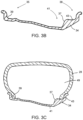
- FIG. 3 B is a cut away view of a wheel rim, in accordance with one aspect of the present disclosure.
- FIG. 3 C is a cut away view of a wheel rim as depicted in FIG. 3 B , further having a tire installed, in accordance with one aspect of the present disclosure
- FIG. 4 A is a cross-sectional view taken along the line 4 - 4 of FIG. 2 A ;
- FIG. 4 B is an enlarged view of the encircled portion of FIG. 4 A ;
- FIG. 5 is a front perspective view depicting a tuning member of the wheel of FIG. 3 A , in accordance with one aspect of the present disclosure
- FIG. 6 is a side view depicting the tuning member of FIG. 5 ;
- FIG. 7 is an example perspective view depicting a wheel and a plurality of tuning members, in accordance with another aspect of the present disclosure.
- FIG. 8 A is a rear perspective view depicting one of the tuning members of the wheel of FIG. 7 , in accordance with one aspect of the present disclosure
- FIG. 8 B is an example front view depicting the tuning member of FIG. 8 A , in accordance with one aspect of the present disclosure
- FIG. 8 C is a side view depicting the tuning member of FIGS. 8 A and 8 B ;
- FIG. 9 A is an example cross sectional perspective view of a wheel having a tuning member installed in accordance with one aspect of the present disclosure
- FIG. 9 B is an example cross sectional rear view of a wheel in accordance with one aspect of the disclosure.
- FIG. 10 is an example perspective view depicting a wheel, in accordance with one aspect of the present disclosure.
- FIG. 11 is an example rear perspective view depicting the wheel of FIG. 10 , wherein the wheel is shown to include a plurality of tuning members disposed about a circumference of the wheel, in accordance with one aspect of the present disclosure
- FIG. 12 is an example enlarged perspective cross section view depicting a tuning member releasably coupled to an outer rim, in accordance with one aspect of the present disclosure
- FIG. 13 is an example enlarged cross section view depicting a tuning member releasably coupled to an outer rim, in accordance with one aspect of the present disclosure
- FIG. 14 is an example perspective view depicting the tuning members of FIGS. 11 - 13 , in accordance with one aspect of the present disclosure
- FIG. 15 is an example rear view depicting the tuning member of FIGS. 11 - 14 , in accordance with one aspect of the present disclosure
- FIG. 16 is an example close up perspective view of a wheel opening, in accordance with another aspect of the disclosure.
- FIG. 17 is an example cut away front view of a wheel, in accordance with another aspect of the disclosure.
- a wheel assembly is provided with a Helmholtz resonator at least partially defined by a hollow chamber defined by a spoke and a tuning member.
- the tuning member at least partially defines a through hole that is in fluid communication with the hollow chamber.
- FIG. 1 illustrates a vehicle 20 .
- the vehicle 20 is shown in FIG. 1 to comprise an automobile.
- a vehicle in accordance with alternative aspects can comprise a sport-utility vehicle (“SUV”), a truck, a van, a cross-over type vehicle (“CUV”), or any of a variety of other suitable vehicles, such as a recreational vehicle or a utility vehicle, for example.
- the vehicle 20 may comprise a plurality of wheel assemblies 22 that are rotatably coupled with a vehicular frame 24 .
- Each of the wheel assemblies 22 may include a wheel 26 and a tire 28 coupled to the wheel 26 .
- the vehicle 20 may include a steering wheel 30 that can facilitate pivoting of the wheel assemblies 22 (e.g., front wheel assemblies and/or rear wheel assemblies) to steer the vehicle 20 .
- An engine (not shown) may be coupled with a transmission (not shown) and may provide motive power to the transmission to facilitate driving of at least one of the wheel assemblies 22 .
- Each of the wheels 26 can define a respective axis of rotation A 1 .
- one of the wheels 26 is depicted and is shown to include an inner hub 32 , an outer rim 34 , and a plurality of spokes 36 that extend between the inner hub 32 and the outer rim 34 .
- the outer rim 34 may define an outer circumference Cl of the wheel 26 .
- the outer rim 34 may include an outboard flange 38 including an outboard bead seat 43 and an inboard flange 35 including an inboard bead seat 39 that are configured to interact with the tire 28 ( FIGS. 3 C, 4 A, and 4 B ) to facilitate an effective seal therebetween.
- the outer rim 34 also includes a drop well 41 positioned inboard of the outboard flange 38 , and an outboard wall 37 positioned inboard of the outboard bead seat 43 that extends from the outboard bead seat 43 to the drop well 41 .
- the inner hub 32 may define a plurality of lug holes 40 that may accommodate lugs (e.g., lug bolts or lug studs) (not shown) that facilitate releasable fastening of the wheel 26 to a wheel hub (not shown).
- the wheel 26 may include a plurality of tuning members 42 that may be releasably coupled with the outer rim 34 along the outer circumference Cl of the outer rim 34 .
- the spoke 36 is shown to include a wall 44 .
- the wall 44 may define a hollow chamber 46 such that the spoke 36 is hollow.
- the outer rim 34 may define an opening 48 that is in fluid communication with the hollow chamber 46 .
- the tuning member 42 may be at least partially inserted into the opening 48 such that the outer rim 34 and the tuning member 42 are coupled together at the opening 48 .
- the tire 28 and the outer rim 34 may define a pressurized air chamber 49 .
- the tuning member 42 is positioned on the wheel assembly 22 to obstruct the opening 48 to at least partially define one or more through holes 52 that has or have a smaller cross sectional area than the opening 48 .
- the through hole 52 may be entirely defined by a body 50 of the tuning member 42 .
- the one or more through holes 52 are in fluid communication with the hollow chamber 46 and the pressurized air chamber 49 .
- the opening 48 can define a diameter D 1 and the through hole 52 can define a diameter D 2 .
- the ratio of the diameter D 2 of the through hole 52 of the tuning member 42 to the diameter D 1 of the opening 48 can be about 1:20 to approximately 1:2. It is to be appreciated that the opening 48 and through hole 52 can be any suitable shape, such as circular, diamond-shaped, oval-shaped, octagonal-shaped, triangular-shaped, square-shaped, rectangular shaped, or otherwise irregularly shaped. For example, in the abovementioned configurations, the diameter can be understood to mean the maximum distance measured across the opening 48 or through hole 52 and through its center.
- the diameter of the opening 48 can be understood to be measured from the outermost point (e.g., furthest away from the inner hub 32 ) at which the tuning member 42 interacts with the opening 48 (illustrated at line 54 in FIG. 4 B ).
- the pressurized chamber 49 is in fluid communication with the hollow chamber 46 of the spoke 36 (e.g., via the through hole 52 of the tuning member 42 ).
- the tuning member 42 and the hollow chamber 46 at least partially defined by the spoke 36 at least partially define a Helmholtz resonator that effectively attenuates road noise generated during operation of the vehicle 20 .
- the tuning member 42 may be tuned through variation of any one of a length of the through hole, width of the through hole, volume of the through hole and/or shape (e.g., the through hole 52 can be sized and/or configured relative to the hollow chamber 46 ) to effectively attenuate the resonance frequencies generated within the pressurized chamber 49 which might otherwise have an adverse effect on road noise.
- Helmholtz resonators can include a neck portion (the portions of the tuning member defining the through hole 52 ) and a cavity (the hollow chamber 46 at least partially defined by the spoke 36 ).
- the resonance frequency of a Helmholtz resonator is dependent on the static pressure in the cavity, the geometry of the neck portion and the volume of the cavity. By altering various geometries of the neck (for example: the diameter, length, and shape) it is possible to alter the range of frequencies which can be effectively attenuated. Based on general, non-limiting principles, the resonance frequency f of a Helmholtz resonator may be found through the following formula (Formula 1):
- the through hole 52 and/or hollow chamber 46 may be tuned to attenuate a range of resonance frequencies generated within the pressurized chamber 49 which might otherwise have an adverse effect on road noise.
- the opening 48 may be defined by the outboard wall 37 of the outer rim 34 , and the body 50 of the tuning member 42 includes an inner surface 500 (See FIGS. 5 and 6 ) that sealingly engage at least a portion of the wall 37 surrounding the opening 48 . It is to be understood that an adhesive or sealant may be applied between the inner surface 500 and the outboard wall 37 to improve the performance of the seal therebetween.
- the tuning member 42 may include a base 505 extending inboardly from the body 50 .
- the base 505 includes an inner surface 510 that sealingly engages a portion 41 A of the drop well 41 .
- the tuning member 42 may include an upper flange 56 and a lower flange 58 .
- the upper and lower flanges 56 , 58 may be configured to be contoured to the adjacent surfaces when the tuning member 42 is inserted into the opening 48 , as illustrated in FIGS. 4 A and 4 B .
- the tuning member 42 can include an outer tab 60 and inner tab 61 that extend from the body 50 and facilitate releasable coupling of the tuning member 42 to the outer rim 34 .
- Either one of or both of the outer and inner tabs 60 , 61 may include a locking feature 63 .
- the locking feature 63 may extend radially outward from abovementioned tabs 60 and/or 61 . As illustrated in FIGS. 4 A and 4 B , the locking feature 63 and/or tabs may interact with, for example, an inner wall of the spoke 36 or outer flange 35 to facilitate retention of the tuning member 42 thereto.
- the tabs 60 and 61 may be angled with respect to each other such that, when the tuning member 42 is inserted into the opening 48 , the tabs 60 and 61 may exert an outward force upon the adjacent wall to hold the tuning member 42 in place.
- the locking feature 63 which may be located on either one of or both of tabs 60 and 61 , may be angled with respect to each other such that, when the tuning member 42 is inserted into the opening 48 , the locking features 63 located on either one of or both of the outer and inner tabs 60 and 61 may exert an outward force upon the wall 44 to hold the tuning member 42 in place.
- the outer tab 60 may be a fixed locating feature that extends from the inner surface 500 along an inner wall 515 of the outboard flange 38
- the inner tab 61 may be thinner than the outer tab 60 so that it is a flexible member that extends from the inner surface 500 that engages a wall portion 65 of the hollow chamber 46 to bias the outer tab 60 against the inner wall of the outboard flange 38 .
- the tuning member 42 can be formed of, but is not limited to, a thermoplastic material, such as polyvinylchloride, for example, an elastomeric material, such as rubber, for example, or any of a variety of suitable alternative non-metallic or metallic materials.
- the tuning member 42 may further be attached to the outer rim 34 through use of a bonding agent or an adhesive.
- the plurality of spokes 36 may be arranged in V-shaped pairs.
- the spokes 36 of each V-shaped pair may be spaced from each other at the outer rim 34 and may intersect with each other at a junction 68 such that the hollow chambers 46 of the V-shaped pair of spokes 36 may be in fluid communication with each other at the junction 68 .
- the junction 68 may be understood to be the portion of the wheel 26 where the two spokes 36 converge and through which the hollow chambers 46 are in fluid communication.
- the junction 68 is shown to be disposed between the outer rim 34 and the axis of rotation and more proximate to the inner hub 32 than the outer rim 34 .
- the junction 68 is shown to be disposed between the inner hub 32 and the outer rim 34 .
- the inner hub 32 may define the junction 68 such that the hollow chambers 46 intersect within the inner hub 32 .
- a junction may be a lateral spoke that extends between the spokes 36 and is spaced from the inner hub 32 and the outer rim 34 .
- three or more spokes may be in fluid communication with each other at the junction. It is to be appreciated that in some aspects, the hollow chambers 46 may not intersect and are thus fluidly isolated from each other at the inner hub 32 .
- the hollow chambers 46 of two or more spokes 36 may converge at a location in close proximity to a hub opening 45 of the wheel 26 .
- the spokes 36 may form a V-shaped pair spaced from each other at the outer rim 34 and may intersect with each other at a location 67 between a junction of the spokes 68 and the hub opening 45 of the wheel. Accordingly, the two spokes 36 and the chambers 46 associated with each spoke 36 may be in fluid communication.
- the wheel 26 may be formed as an as-cast one-piece construction. It will be appreciated that the wheel 26 being described as as-cast should be understood to mean that the wheel 26 is cast by providing a molten metal material (e.g., a castable material), such as an aluminum alloy or steel, into a mold, allowing the molten material to solidify. In some aspects, further processing, such as welding or machining, may not be necessary to form the hollow spokes 36 . However, machining may be performed on the as-cast wheel 26 to, for example, refine openings or to remove material to balance the wheel.
- a molten metal material e.g., a castable material
- further processing such as welding or machining
- the tuning members 42 may be installed onto the wheel once the wheel 26 has been cast and has undergone any finishing processes (e.g., CNC machining) that make the wheel 26 ready for use.
- the tuning members 42 may be held in place though the methods mentioned throughout the disclosure and/or further may be attached to the opening 48 through use of a bonding agent or an adhesive.
- the wheel 26 may be provided as an as-cast construction that defines an upper lobe 64 of the hollow chamber 46 that extends radially beyond the outer rim 34 and into the bead seat 38 (as measured from the axis of rotation A 1 ).
- the upper lobe 64 may be disposed above a centerline L 1 defined by the opening 48 of the wheel 26 .
- FIGS. 7 - 9 An alternative aspect of a wheel 126 and a plurality of tuning members 142 is shown in FIGS. 7 - 9 .
- the wheel 126 and the tuning members 142 may be similar to, or the same as in many respects as, the wheel 26 and the tuning members of FIGS. 1 - 6 .
- the wheel 126 may include a plurality of spokes 136 that are hollow.
- Each of the tuning members 142 may be associated with one of the spokes 136 .
- Each of the spokes 136 may include a chamber 146 extending towards a radially central portion of the wheel and ending at a center wall 222 .
- the center wall may extend from each of the lug holes 240 .
- the distance between the lug holes 240 and the center wall 222 may be optimized to control the geometry of the resonator chamber or may be optimized to balance and/or to provide a desired weight to the wheel. Further the thickness of the material between the lug hole 240 and bottom wall 222 may be varied according to the desired load carrying and strength characteristics of the wheel.
- each of the abovementioned spokes 136 may include a chamber 146 that extends toward the center wall 222 .
- the center wall 222 may be provided so as to conform to and provide a thickness in the material between the center wall 222 and each of the lug holes 240 . Further the center wall 222 may be provided so as to conform to and provide a thickness in the material between the hub opening 245 and the center wall 222 defining a bottom portion of the chamber located radially inward toward an axis of the wheel.
- the wheel may further include a divider portion 247 dividing each of the chambers 146 so as to form an individual chamber corresponding to each spoke 136 . Further the divider portions 247 may be omitted between a plurality of spokes 136 so that at least the chambers 146 of two spokes 136 are in fluid communication.
- the tuning members 142 may include a body 150 and a base 158 .
- the body 150 includes an inner surface 156 (which may hereinafter be referred to interchangeably as an outer flange) that sealingly engages at least a portion of the wall (an example of which is shown in FIGS. 3 B-C , reference 37 ) surrounding the opening (an example of which is shown in FIGS. 4 A-B , reference 48 ). It is to be understood that an adhesive or sealant may be applied between the inner surface 156 and the outboard wall (see FIG. 4 B ) to improve the performance of the seal therebetween.
- the base 158 includes an inner surface 158 A (which may hereinafter be referred to interchangeable as an inner flange) that sealingly engages a portion of the drop well (an example of which is shown in FIGS. 3 B-C , reference 41 ) An adhesive or sealant may also be applied between the inner surface 158 A and the drop well.
- the tuning member 142 may include inner tabs 161 and outer tabs 160 . Either one or both of the outer and inner tabs 160 and 161 may include a locking feature 163 . The locking feature 163 may extend radially outward from abovementioned tabs 160 and/or 161 .
- the body 150 of the tuning member 142 may define one or more through holes 152 , 153 , as illustrated by in the representative tuning member 142 depicted in FIGS. 7 - 9 .
- the tuning member 142 may be formed of a thermoplastic material, such as polyvinylchloride, for example, an elastomeric material, such as rubber, for example, or any of a variety of suitable alternative non-metallic or metallic materials.
- a thermoplastic material such as polyvinylchloride, for example, an elastomeric material, such as rubber, for example, or any of a variety of suitable alternative non-metallic or metallic materials.
- the tuning member 142 may define with a hollow chamber 146 a Helmholtz resonator that effectively attenuates road noise generated during operation of the vehicle 20 ( FIG. 1 ).
- the tuning member 142 may be tuned through variation of any one of a length of the through hole 152 , width of the through hole, volume of the through hole, shape and/or the number of through holes (e.g., the through hole 152 can be sized and/or configured relative to the hollow chamber 146 ) to effectively attenuate the resonance frequencies generated within the pressurized chamber 149 which might otherwise have an adverse effect on road noise.
- tuning member 142 may further include a number of openings other than through holes 152 and 153 .
- the tuning member 142 and through holes 152 and 153 may be dimensioned based on abovementioned formulas 1 and 2. Further the though holes 152 may be dimensioned using the abovementioned methods and/or other methods to effectively attenuate the resonance frequencies generated within the pressurized chamber 149 . Through holes 152 and 153 may alternatively be modified as a single though hole or a plurality of through holes. It is to be appreciated that any of a variety of tuning member and/or through hole arrangements are contemplated to achieve effective resonance frequency attenuation. In a non-limiting example, the holes 152 and 153 can be ovals or any other shape sized to provide damping at the resonance frequency. It is also to be appreciated that a wheel can be provided in any of a variety of suitable arrangements (e.g., spoke arrangements) that facilitate resonance frequency attenuation apart from, or in conjunction with a resonator.
- suitable arrangements e.g., spoke arrangements
- FIGS. 10 and 11 An alternative aspect of a wheel 226 and a plurality of tuning members 242 is shown in FIGS. 10 and 11 .
- the wheel 226 may be similar to, or the same as in many respects as, the wheel 26 or 126 and the tuning members of FIGS. 1 - 6 and FIGS. 8 and 9 .
- the tuning member 242 may comprise a body 250 that defines a through hole 252 .
- the tuning member 242 may further include an outer flange or body 256 having an inner surface 256 A (which may hereinafter be referred to interchangeably as a body inner surface) and an inner flange or base 258 .
- the inner flange 258 may further include an inner flange bottom surface 258 A (which may hereinafter be referred to interchangeably as a base inner surface). At least one of the inner flange 258 , and inner flange bottom surface 258 A engage with at least corresponding recessed portions of the wheel proximal to the drop wall and surrounding the opening. For example, as shown in FIGS. 12 - 16 , the inner flange 258 and inner flange bottom surface 258 A may sealingly engage with at least recessed portions of the drop wall 550 and 257 respectively. Further, at least one of the inner surface of the body 256 A and the body 256 may sealingly engage with the wall portions 259 and 259 A respectively.
- an adhesive or sealant may be applied between the outer flange 256 and inner flange 258 and the recessed portions of the drop wall 257 and 259 to improve the performance of the seal therebetween. Further, it is to be understood that the abovementioned sealing portions to sealingly engage the tuning member with the wheel may be applied to any of the variations mentioned throughout the disclosure.
- the inner flange 258 may fill a recessed portions 257 and 259 in the wall 244 .
- the outer flange 258 may be contoured to the bead seat 238 or to an upper recessed portion 255 best seen in FIG. 16 .
- the outer and inner flanges 256 and 258 may interact with respective surfaces of the recessed portions 257 , 259 and/or 255 when the tuning member 242 is inserted into the opening 248 , as illustrated in FIGS. 12 - 13 .
- the tuning member 242 may include an outer tab 260 and an inner tab 261 and may exert an outward force upon the wall 244 to hold the tuning member 242 in place.
- Tabs 260 and/or 261 may be a single tab or be comprised of a plurality of tabs. Further, a locking feature 263 may be located on either one of or both of tabs 260 and 261 . The locking feature may extend radially outward from abovementioned tabs 260 and/or 261 . The locking feature and/or tabs may be angled such that when the tuning member 242 is inserted into the opening 248 , the locking feature 263 located on either one of or both of 260 and 261 may exert an outward force upon the wall 244 to hold the tuning member 242 in place.
- the wall portion 244 may further include a single or a plurality of ridged portions 262 . The ridged portions 262 may protrude from the wall portion 244 such that a locking feature 263 of the tuning member 242 interacts with the ridge portion 244 when the tuning member 242 is installed into the wall opening 248 .
- the tuning member 242 may be formed of a thermoplastic material, such as polyvinylchloride, for example, an elastomeric material, such as rubber, for example, or any of a variety of suitable alternative non-metallic or metallic materials.
- a thermoplastic material such as polyvinylchloride, for example, an elastomeric material, such as rubber, for example, or any of a variety of suitable alternative non-metallic or metallic materials.
- the tuning member 242 and a hollow chamber 246 at least partially define a Helmholtz resonator that effectively attenuates road noise generated during operation of the vehicle 20 ( FIG. 1 ).
- the tuning member 242 may be tuned through variation of any one of a length of the through holes 252 and 253 , width of the through hole, volume of the through hole, shape and/or the number of through holes (e.g., the through hole 252 and/or 253 can be sized and/or configured relative to the hollow chamber 246 ) to effectively attenuate the resonance frequencies generated within the pressurized chamber 249 which might otherwise have an adverse effect on road noise.
- the tuning member 242 may further include a plurality of openings.
- the tuning member 242 and through holes 252 and 253 may be dimensioned based on abovementioned formulas 1 and 2. Further the though holes 252 may be dimensioned using other methods to effectively attenuate the resonance frequencies generated within the pressurized chamber 249 .
- Through holes 252 may be modified to include a single through hole or a plurality of through holes. It is to be appreciated that any of a variety of tuning member and/or through hole arrangements are contemplated to achieve effective resonance frequency attenuation.
- the holes 252 , 253 may be ovals or any other shape sized to provide damping at the resonance frequency.
- a wheel can be provided in any of a variety of suitable arrangements (e.g., spoke arrangements) that facilitate resonance frequency attenuation apart from, or in conjunction with a tuning member.
Abstract
Description
where c is the speed of sound, s is a cross sectional area of the neck portion (e.g. D2) and v is the volume of the cavity (e.g. hollow chamber 46). R′ in the equation above may be the effective length of the neck which is represented by the following formula (Formula 2):
R′=R+0.3D, (Formula 2)
where R is the actual length of the neck portion and D is a hydraulic diameter of the neck portion. Based on the above principles, the through
Claims (20)
Priority Applications (1)
| Application Number | Priority Date | Filing Date | Title |
|---|---|---|---|
| US16/854,542 US11633976B2 (en) | 2019-04-30 | 2020-04-21 | Vehicular wheel having a spoke defining a hollow chamber and vehicles including same |
Applications Claiming Priority (2)
| Application Number | Priority Date | Filing Date | Title |
|---|---|---|---|
| US201962840998P | 2019-04-30 | 2019-04-30 | |
| US16/854,542 US11633976B2 (en) | 2019-04-30 | 2020-04-21 | Vehicular wheel having a spoke defining a hollow chamber and vehicles including same |
Publications (2)
| Publication Number | Publication Date |
|---|---|
| US20200346487A1 US20200346487A1 (en) | 2020-11-05 |
| US11633976B2 true US11633976B2 (en) | 2023-04-25 |
Family
ID=73017475
Family Applications (1)
| Application Number | Title | Priority Date | Filing Date |
|---|---|---|---|
| US16/854,542 Active 2041-08-09 US11633976B2 (en) | 2019-04-30 | 2020-04-21 | Vehicular wheel having a spoke defining a hollow chamber and vehicles including same |
Country Status (1)
| Country | Link |
|---|---|
| US (1) | US11633976B2 (en) |
Families Citing this family (2)
| Publication number | Priority date | Publication date | Assignee | Title |
|---|---|---|---|---|
| JP2020006789A (en) * | 2018-07-06 | 2020-01-16 | 本田技研工業株式会社 | Vehicular wheel |
| KR20210147683A (en) * | 2020-05-29 | 2021-12-07 | 현대자동차주식회사 | Wheel for vehicle and method for manufacturing the same |
Citations (34)
| Publication number | Priority date | Publication date | Assignee | Title |
|---|---|---|---|---|
| US4610482A (en) | 1985-03-07 | 1986-09-09 | Motor Wheel Corporation | Vehicle wheel with disc forming outer tire retaining flange |
| US5313996A (en) | 1992-03-02 | 1994-05-24 | Paul Bragg | Wheel having spoke-integrated tire inflation passageway |
| US5538329A (en) | 1991-11-23 | 1996-07-23 | Dr. Ing. H.C.F. Porsche Ag | Wheel for a motor vehicle and method of making same |
| US5564792A (en) | 1994-12-13 | 1996-10-15 | Hayes Wheels International, Inc. | Balancing weight attachment system for a vehicle wheel |
| US5641208A (en) | 1994-08-27 | 1997-06-24 | Dr. Ing. H.C.F. Porsche Ag | Wheel for a motor vehicle having hollow spokes and a centrally arranged valve |
| DE19634535C1 (en) * | 1996-08-27 | 1997-08-07 | Porsche Ag | Method for producing cast one-part vehicle wheel |
| EP0936083A2 (en) * | 1998-02-10 | 1999-08-18 | Dr.Ing. h.c.F. Porsche Aktiengesellschaft | Vehicle wheel |
| US6024415A (en) | 1995-10-11 | 2000-02-15 | Dr. Ing. H.C.F. Porsche Ag | Wheel for a motor vehicle and method of making same |
| US6106075A (en) | 1998-06-02 | 2000-08-22 | Honda Giken Kogyo Kabushiki Kaisha | Road wheel with improved vibration characteristics and method of constructing and utilizing same |
| US6234581B1 (en) | 1996-06-25 | 2001-05-22 | Dr. Ing. H.C.F. Porsche Ag | Wheel for a motor vehicle |
| US6309026B1 (en) | 1997-02-12 | 2001-10-30 | Saab Automobile Ab | Method and arrangement for sound-suppression in wheels |
| US6312059B1 (en) | 1999-03-27 | 2001-11-06 | Dr. Ing. H.C.F. Porsche Aktiengesellschaft | Vehicle wheel |
| US6325462B1 (en) | 1997-12-11 | 2001-12-04 | Dr. Ing. H.C.F. Porsche Ag | Motor vehicle wheel having hollow spokes |
| US6364425B1 (en) | 1998-12-29 | 2002-04-02 | Hayes Lemmerz International, Inc. | Cast wheel with hollow core insert |
| US6516849B2 (en) | 1999-09-29 | 2003-02-11 | Michelin Recherche Et Technique S.A. | Safety support with a noise attenuator for a vehicle wheel |
| JP2004090669A (en) | 2002-08-29 | 2004-03-25 | Bridgestone Corp | Method for manufacturing rim wheel |
| US6758533B1 (en) | 1999-06-11 | 2004-07-06 | Dr. Ing. H.C.F. Porsche Ag | Wheel for a motor vehicle and a method of making the wheel |
| US6837549B2 (en) | 2001-01-11 | 2005-01-04 | Hitachi Metals, Ltd. | Light alloy wheel for vehicle and method and apparatus for producing same |
| US7013940B2 (en) | 2001-04-19 | 2006-03-21 | Michelin Recherche Et Technique S.A. | Device for attenuating cavity noise in a tire and wheel |
| JP2006231966A (en) | 2005-02-22 | 2006-09-07 | Toyota Motor Corp | Rim wheel and manufacturing method thereof |
| US7152643B2 (en) | 2001-09-18 | 2006-12-26 | Bridgestone Corporation | Rim wheel, and tire-rim assembly |
| JP2007326533A (en) * | 2006-06-09 | 2007-12-20 | Nissan Motor Co Ltd | Spoke wheel and noise prevention method for vehicle |
| US20080164750A1 (en) | 2003-10-10 | 2008-07-10 | Aldo Vanetta | Method For Mounting a Tire to a Wheel Rim and Counterbalacing Weight to be Attached to a Wheel Rim |
| US7487668B2 (en) | 2006-01-20 | 2009-02-10 | Nissan Motor Co., Ltd. | Fixing structure for pneumatic tire pressure sensor, and tire wheel with protector for pneumatic tire pressure sensor |
| JP2009029348A (en) | 2007-07-30 | 2009-02-12 | Chuo Motor Wheel Co Ltd | Vehicular wheel |
| US7694706B2 (en) | 2004-01-20 | 2010-04-13 | The Yokohama Rubber Co., Ltd. | Tire wheel assembly |
| US20100123350A1 (en) | 2008-11-18 | 2010-05-20 | Mcneill Christopher King | Wheel and Balancer |
| US7976107B2 (en) | 2009-01-30 | 2011-07-12 | Lance Okada | Vehicle wheel rim having lateral balance plane |
| JP2011173479A (en) | 2010-02-24 | 2011-09-08 | Chuo Motor Wheel Co Ltd | Vehicular wheel |
| US8231180B2 (en) | 2005-12-08 | 2012-07-31 | Hayes Lemmerz International, Inc. | Fabricated vehicle wheel and method for producing same |
| JP2012171459A (en) | 2011-02-21 | 2012-09-10 | Chuo Motor Wheel Co Ltd | Vehicular wheel |
| US8286679B2 (en) | 2008-10-15 | 2012-10-16 | Honda Motor Co., Ltd. | Vehicle wheel |
| US20140116593A1 (en) | 2012-10-29 | 2014-05-01 | Wheel Pros, Llc | Reduced weight wheel configured for use with valve stem and or tire sensor |
| KR20220010881A (en) * | 2020-07-20 | 2022-01-27 | 현대자동차주식회사 | Hollow spoke sound absorbing wheel for vehicle and manufacturing method of the same |
-
2020
- 2020-04-21 US US16/854,542 patent/US11633976B2/en active Active
Patent Citations (35)
| Publication number | Priority date | Publication date | Assignee | Title |
|---|---|---|---|---|
| US4610482A (en) | 1985-03-07 | 1986-09-09 | Motor Wheel Corporation | Vehicle wheel with disc forming outer tire retaining flange |
| US5538329A (en) | 1991-11-23 | 1996-07-23 | Dr. Ing. H.C.F. Porsche Ag | Wheel for a motor vehicle and method of making same |
| US5313996A (en) | 1992-03-02 | 1994-05-24 | Paul Bragg | Wheel having spoke-integrated tire inflation passageway |
| US5641208A (en) | 1994-08-27 | 1997-06-24 | Dr. Ing. H.C.F. Porsche Ag | Wheel for a motor vehicle having hollow spokes and a centrally arranged valve |
| US5564792A (en) | 1994-12-13 | 1996-10-15 | Hayes Wheels International, Inc. | Balancing weight attachment system for a vehicle wheel |
| US6231129B1 (en) | 1995-10-11 | 2001-05-15 | Dr. Ing. H.C.F. Porsche Ag | Wheel for a motor vehicle and method of making same |
| US6024415A (en) | 1995-10-11 | 2000-02-15 | Dr. Ing. H.C.F. Porsche Ag | Wheel for a motor vehicle and method of making same |
| US6234581B1 (en) | 1996-06-25 | 2001-05-22 | Dr. Ing. H.C.F. Porsche Ag | Wheel for a motor vehicle |
| DE19634535C1 (en) * | 1996-08-27 | 1997-08-07 | Porsche Ag | Method for producing cast one-part vehicle wheel |
| US6309026B1 (en) | 1997-02-12 | 2001-10-30 | Saab Automobile Ab | Method and arrangement for sound-suppression in wheels |
| US6325462B1 (en) | 1997-12-11 | 2001-12-04 | Dr. Ing. H.C.F. Porsche Ag | Motor vehicle wheel having hollow spokes |
| EP0936083A2 (en) * | 1998-02-10 | 1999-08-18 | Dr.Ing. h.c.F. Porsche Aktiengesellschaft | Vehicle wheel |
| US6106075A (en) | 1998-06-02 | 2000-08-22 | Honda Giken Kogyo Kabushiki Kaisha | Road wheel with improved vibration characteristics and method of constructing and utilizing same |
| US6364425B1 (en) | 1998-12-29 | 2002-04-02 | Hayes Lemmerz International, Inc. | Cast wheel with hollow core insert |
| US6312059B1 (en) | 1999-03-27 | 2001-11-06 | Dr. Ing. H.C.F. Porsche Aktiengesellschaft | Vehicle wheel |
| US6758533B1 (en) | 1999-06-11 | 2004-07-06 | Dr. Ing. H.C.F. Porsche Ag | Wheel for a motor vehicle and a method of making the wheel |
| US6516849B2 (en) | 1999-09-29 | 2003-02-11 | Michelin Recherche Et Technique S.A. | Safety support with a noise attenuator for a vehicle wheel |
| US6837549B2 (en) | 2001-01-11 | 2005-01-04 | Hitachi Metals, Ltd. | Light alloy wheel for vehicle and method and apparatus for producing same |
| US7013940B2 (en) | 2001-04-19 | 2006-03-21 | Michelin Recherche Et Technique S.A. | Device for attenuating cavity noise in a tire and wheel |
| US7152643B2 (en) | 2001-09-18 | 2006-12-26 | Bridgestone Corporation | Rim wheel, and tire-rim assembly |
| JP2004090669A (en) | 2002-08-29 | 2004-03-25 | Bridgestone Corp | Method for manufacturing rim wheel |
| US20080164750A1 (en) | 2003-10-10 | 2008-07-10 | Aldo Vanetta | Method For Mounting a Tire to a Wheel Rim and Counterbalacing Weight to be Attached to a Wheel Rim |
| US7694706B2 (en) | 2004-01-20 | 2010-04-13 | The Yokohama Rubber Co., Ltd. | Tire wheel assembly |
| JP2006231966A (en) | 2005-02-22 | 2006-09-07 | Toyota Motor Corp | Rim wheel and manufacturing method thereof |
| US8231180B2 (en) | 2005-12-08 | 2012-07-31 | Hayes Lemmerz International, Inc. | Fabricated vehicle wheel and method for producing same |
| US7487668B2 (en) | 2006-01-20 | 2009-02-10 | Nissan Motor Co., Ltd. | Fixing structure for pneumatic tire pressure sensor, and tire wheel with protector for pneumatic tire pressure sensor |
| JP2007326533A (en) * | 2006-06-09 | 2007-12-20 | Nissan Motor Co Ltd | Spoke wheel and noise prevention method for vehicle |
| JP2009029348A (en) | 2007-07-30 | 2009-02-12 | Chuo Motor Wheel Co Ltd | Vehicular wheel |
| US8286679B2 (en) | 2008-10-15 | 2012-10-16 | Honda Motor Co., Ltd. | Vehicle wheel |
| US20100123350A1 (en) | 2008-11-18 | 2010-05-20 | Mcneill Christopher King | Wheel and Balancer |
| US7976107B2 (en) | 2009-01-30 | 2011-07-12 | Lance Okada | Vehicle wheel rim having lateral balance plane |
| JP2011173479A (en) | 2010-02-24 | 2011-09-08 | Chuo Motor Wheel Co Ltd | Vehicular wheel |
| JP2012171459A (en) | 2011-02-21 | 2012-09-10 | Chuo Motor Wheel Co Ltd | Vehicular wheel |
| US20140116593A1 (en) | 2012-10-29 | 2014-05-01 | Wheel Pros, Llc | Reduced weight wheel configured for use with valve stem and or tire sensor |
| KR20220010881A (en) * | 2020-07-20 | 2022-01-27 | 현대자동차주식회사 | Hollow spoke sound absorbing wheel for vehicle and manufacturing method of the same |
Also Published As
| Publication number | Publication date |
|---|---|
| US20200346487A1 (en) | 2020-11-05 |
Similar Documents
| Publication | Publication Date | Title |
|---|---|---|
| US9375976B1 (en) | Wheel with Y-shaped spoke configuration | |
| US11633976B2 (en) | Vehicular wheel having a spoke defining a hollow chamber and vehicles including same | |
| EP1092567B1 (en) | Wheel structure | |
| KR101541031B1 (en) | Automotive wheel with a cavity between the bolt holes in the hub mounting | |
| JP3400787B2 (en) | How to correct tire imbalance | |
| JP2002234304A (en) | Rim wheel with core and tire rim wheel assembly | |
| JP4102756B2 (en) | Rim wheel, tire / rim assembly | |
| US5820709A (en) | Vehicle tire and rim combination | |
| JP2000351302A (en) | Wheel rim | |
| JPS63130412A (en) | Tyre structure for vehicle | |
| JP3776722B2 (en) | Rim wheel | |
| JP2009029348A (en) | Vehicular wheel | |
| JP3808635B2 (en) | Road noise suppression device | |
| JP4188030B2 (en) | Tire wheel | |
| US20190366764A1 (en) | Vehicle wheel | |
| JP2019196045A (en) | Vehicle wheel | |
| JP3043777B2 (en) | Pneumatic tire | |
| JP2006347477A (en) | Vehicle wheel | |
| JPH01115701A (en) | Low noise tyre wheel | |
| EP3795371B1 (en) | Vehicle wheel structure and resonator | |
| JP2002234305A (en) | Rim wheel | |
| EP1462275A1 (en) | Noise reducer for vehicle wheel | |
| JP2001055003A (en) | Damper installing structure of wheel with damper | |
| JP2020083022A (en) | Vehicular wheel | |
| KR20190127147A (en) | Vehicle wheel with noise attenuation function |
Legal Events
| Date | Code | Title | Description |
|---|---|---|---|
| FEPP | Fee payment procedure |
Free format text: ENTITY STATUS SET TO UNDISCOUNTED (ORIGINAL EVENT CODE: BIG.); ENTITY STATUS OF PATENT OWNER: LARGE ENTITY |
|
| STPP | Information on status: patent application and granting procedure in general |
Free format text: APPLICATION DISPATCHED FROM PREEXAM, NOT YET DOCKETED |
|
| AS | Assignment |
Owner name: HONDA MOTOR CO., LTD., JAPAN Free format text: ASSIGNMENT OF ASSIGNORS INTEREST;ASSIGNOR:NELSON, JOSEPH;REEL/FRAME:053138/0814 Effective date: 20200512 |
|
| STPP | Information on status: patent application and granting procedure in general |
Free format text: DOCKETED NEW CASE - READY FOR EXAMINATION |
|
| STPP | Information on status: patent application and granting procedure in general |
Free format text: NON FINAL ACTION MAILED |
|
| STCF | Information on status: patent grant |
Free format text: PATENTED CASE |