EP1220421A2 - Rotatorischer Motor kleinen Ausmasses - Google Patents
Rotatorischer Motor kleinen Ausmasses Download PDFInfo
- Publication number
- EP1220421A2 EP1220421A2 EP01310518A EP01310518A EP1220421A2 EP 1220421 A2 EP1220421 A2 EP 1220421A2 EP 01310518 A EP01310518 A EP 01310518A EP 01310518 A EP01310518 A EP 01310518A EP 1220421 A2 EP1220421 A2 EP 1220421A2
- Authority
- EP
- European Patent Office
- Prior art keywords
- rotating body
- rotary motor
- stator
- hollow type
- motor according
- Prior art date
- Legal status (The legal status is an assumption and is not a legal conclusion. Google has not performed a legal analysis and makes no representation as to the accuracy of the status listed.)
- Withdrawn
Links
Images


Classifications
-
- F—MECHANICAL ENGINEERING; LIGHTING; HEATING; WEAPONS; BLASTING
- F16—ENGINEERING ELEMENTS AND UNITS; GENERAL MEASURES FOR PRODUCING AND MAINTAINING EFFECTIVE FUNCTIONING OF MACHINES OR INSTALLATIONS; THERMAL INSULATION IN GENERAL
- F16C—SHAFTS; FLEXIBLE SHAFTS; ELEMENTS OR CRANKSHAFT MECHANISMS; ROTARY BODIES OTHER THAN GEARING ELEMENTS; BEARINGS
- F16C25/00—Bearings for exclusively rotary movement adjustable for wear or play
- F16C25/06—Ball or roller bearings
- F16C25/08—Ball or roller bearings self-adjusting
-
- H—ELECTRICITY
- H02—GENERATION; CONVERSION OR DISTRIBUTION OF ELECTRIC POWER
- H02K—DYNAMO-ELECTRIC MACHINES
- H02K7/00—Arrangements for handling mechanical energy structurally associated with dynamo-electric machines, e.g. structural association with mechanical driving motors or auxiliary dynamo-electric machines
- H02K7/08—Structural association with bearings
- H02K7/083—Structural association with bearings radially supporting the rotary shaft at both ends of the rotor
-
- H—ELECTRICITY
- H02—GENERATION; CONVERSION OR DISTRIBUTION OF ELECTRIC POWER
- H02K—DYNAMO-ELECTRIC MACHINES
- H02K7/00—Arrangements for handling mechanical energy structurally associated with dynamo-electric machines, e.g. structural association with mechanical driving motors or auxiliary dynamo-electric machines
- H02K7/08—Structural association with bearings
- H02K7/086—Structural association with bearings radially supporting the rotor around a fixed spindle; radially supporting the rotor directly
- H02K7/088—Structural association with bearings radially supporting the rotor around a fixed spindle; radially supporting the rotor directly radially supporting the rotor directly
-
- F—MECHANICAL ENGINEERING; LIGHTING; HEATING; WEAPONS; BLASTING
- F16—ENGINEERING ELEMENTS AND UNITS; GENERAL MEASURES FOR PRODUCING AND MAINTAINING EFFECTIVE FUNCTIONING OF MACHINES OR INSTALLATIONS; THERMAL INSULATION IN GENERAL
- F16C—SHAFTS; FLEXIBLE SHAFTS; ELEMENTS OR CRANKSHAFT MECHANISMS; ROTARY BODIES OTHER THAN GEARING ELEMENTS; BEARINGS
- F16C19/00—Bearings with rolling contact, for exclusively rotary movement
- F16C19/02—Bearings with rolling contact, for exclusively rotary movement with bearing balls essentially of the same size in one or more circular rows
- F16C19/04—Bearings with rolling contact, for exclusively rotary movement with bearing balls essentially of the same size in one or more circular rows for radial load mainly
- F16C19/06—Bearings with rolling contact, for exclusively rotary movement with bearing balls essentially of the same size in one or more circular rows for radial load mainly with a single row or balls
-
- F—MECHANICAL ENGINEERING; LIGHTING; HEATING; WEAPONS; BLASTING
- F16—ENGINEERING ELEMENTS AND UNITS; GENERAL MEASURES FOR PRODUCING AND MAINTAINING EFFECTIVE FUNCTIONING OF MACHINES OR INSTALLATIONS; THERMAL INSULATION IN GENERAL
- F16C—SHAFTS; FLEXIBLE SHAFTS; ELEMENTS OR CRANKSHAFT MECHANISMS; ROTARY BODIES OTHER THAN GEARING ELEMENTS; BEARINGS
- F16C2380/00—Electrical apparatus
- F16C2380/26—Dynamo-electric machines or combinations therewith, e.g. electro-motors and generators
-
- H—ELECTRICITY
- H02—GENERATION; CONVERSION OR DISTRIBUTION OF ELECTRIC POWER
- H02K—DYNAMO-ELECTRIC MACHINES
- H02K7/00—Arrangements for handling mechanical energy structurally associated with dynamo-electric machines, e.g. structural association with mechanical driving motors or auxiliary dynamo-electric machines
- H02K7/08—Structural association with bearings
- H02K7/09—Structural association with bearings with magnetic bearings
Definitions
- the present invention relates to a small size rotary motor, and in particular, to a high-precision small size rotary motor which has a prestress function and can be used by itself.
- a rotation of a motor is transmitted to an object to be driven via a rotation transmitting mechanism, which comprises components such as gears. It has been practiced to increase the accuracy of rotation by improving the accuracy of control relating to rotation such as control of a rotating speed, control of a rotation angle, etc., and by reducing backlash of bearings in the rotation transmitting mechanism.
- a rotor 2 In an outer casing 1, a rotor 2 is accommodated. On the rotor 2, shafts 3 and 4 are extended from both ends respectively, and one of the shafts, i.e. the shaft 4, serves as an output shaft. The shafts 3 and 4 are rotatably supported in the outer casing 1 via ball bearings 5 and 6.
- stator 8 On an outer peripheral surface of the rotor 2, permanent magnets 7 are provided in a circumferential direction so as to have different magnetic poles alternately.
- the central part of the outer casing 1 facing to the permanent magnets 7 is a stator 8.
- the stator is equally divided as necessary in a circumferential direction.
- coils 9 are wound. By supplying an electric current to the coils 9, the rotor 2 is rotated.
- Fig. 5 exaggeratedly shows the state that prestress in the axial direction is given between the inner race 11 and the outer race 12 of each of the ball bearings 5 and 6.
- Supporting structure of each of the outer races 12 of the ball bearings 5 and 6 differs from the structure shown in Fig. 4. However, it is the same when the outer race is restrained from movement in the axial direction.
- a bearing retainer 14 has a relief bore 15, a bearing engaging bore 16 having a diameter slightly larger than a diameter of the relief bore 15, and a screw bore 17 having a diameter larger than the diameter of the bearing engaging bore 16.
- the ball bearings 5 and 6 are engaged in the bearing engaging bore 16.
- a collar 18 is attached between the ball bearings 5 and 6.
- the outer race 12 of the ball bearing 6 is fastened by a ring nut 19 screwed in the screw bore 17, and the outer races 12 of the ball bearings 5 and 6 are restrained in the axial direction.
- the inner race 11 of the ball bearing 5 is engaged on the shaft 3, and the inner race 11 of the ball bearing 6 is engaged on the shaft 4.
- the inner race 11 of the ball bearing 5 is restrained from displacement in a leftward direction (in the figure), and the inner race 11 of the ball bearing 6 is restrained by a nut 21 screwed on the shaft 4 from movement in a rightward direction (in the figure).
- a wave washer 22 is provided in a compressed state.
- backlash differs slightly from each other according to the error during the manufacturing process. For this reason, if priority is given on the accuracy, backlash must be adjusted in each individual case by manual operation. If it is too loose, the accuracy is decreased. If fastened too tightly, service life of the ball bearings is shortened. Thus, it is very difficult to adjust, and the accuracy depends much on the skill of the worker.
- the present invention provides a small size rotary motor comprising a rotating body, a stator and bearings, wherein the rotating body is supported rotatably on the stator via bearings, and a magnetic force in an axial direction acts on the rotating body between the rotating body and the stator.
- the present invention provides the small size rotary motor as described above, wherein a magnetic plate in a doughnut-like shape is provided on the stator side, the magnetic plate is provided at a face-to-face position to an end surface of the rotating body, and a magnetic force acts between the magnetic plate and the rotating body.
- the present invention provides the small size rotary motor as described above, wherein the magnetic plate is made of silicon steel.
- the present invention provides the small size rotary motor as described above, wherein a hollow type fixed shaft is fixed on the stator side, a space is formed in a cylindrical shape around the hollow type fixed shaft and a hollow type rotating body is engaged on the hollow type fixed shaft via the bearings, wherein a magnetic force in the axial direction acts on the rotating body. Further, the present invention provides the small size rotary motor as described above, wherein the magnetic plate is provided at a face-to-face position to end surfaces of magnets provided around the rotating body.
- the present invention provides the small size rotary motor as described above, wherein the end surface of the rotating body is provided at a face-to-face position to a portion where the hollow type fixed shaft and the stator side are fixed, and a magnetic force acts between the end surface of the rotating body and the portion. Further, the present invention provides the small size rotary motor as described above, wherein the portion is made of silicon steel. Also, the present invention provides the small size rotary motor as described above, wherein an optical member is provided in a hollow portion of the rotating body.
- Fig. 1 shows a first embodiment of the present invention, which is applied on a small size rotary motor having two bearings.
- An outer casing 1 is composed so that a stator 8 is sandwiched by end plates 25 and 26.
- a ball bearing 5 is engaged with the end plate 25, and a ball bearing 6 is engaged with the end plate 26.
- a magnetic plate 27 is sandwiched, and the magnetic plate 27 is magnetically insulated from the stator 8 and the end plate 26.
- a shaft 3 extended from a rotor 2 is supported by the ball bearing 5, and a shaft 4 is supported by the ball bearing 6.
- outer races of the ball bearings 5 and 6 are restrained from displacement in an axial direction.
- At least one of the inner races of the ball bearings 5 and 6 is fixed on the rotor 2 and is integrally displaced (i.e. moves with it).
- the magnetic plate 27 is designed in a doughnut-like shape, and its inner periphery is at a face-to-face position to the permanent magnet 7 with a very small gap between the magnetic plate 27 and the permanent magnet 7. Its inner diameter is equal to or slightly smaller than an outer diameter of the rotor 2.
- a ferromagnetic material with lower hysteresis e.g. a silicon steel plate being the same type of material as the stator 8, is used.
- the magnetic plate 27 is magnetized by the permanent magnet 7. Attraction force is generated between the permanent magnet 7 and the magnetic plate 27, and the rotor 2 is pushed in a rightward direction in Fig. 1.
- the rotor 2 is displaced in the axial direction by an extent of backlash of the ball bearings 5 and 6. Because outer races 12 of the ball bearings 5 and 6 are restrained in the axial direction, when the rotor 2 is displaced, relative displacement occurs between the inner races 11 and the outer races 12 of at least one of the ball bearings 5 and 6. As a result, prestress is given, and backlash of the bearings is eliminated.
- magnetic force is utilized, and not mechanical repulsive force.
- the structure is extremely simplified, and there is no need to perform physical adjustment by manual operation. Also, complicated fabrication procedure requiring high precision is not needed.
- the magnetic plate 27 may be designed in such manner that the magnetic plate 27 is divided in the circumferential direction and is magnetically integrated with the stator 8, and in such manner that the magnetic plate 27 is magnetized by the coils 9, and only attraction force occurs between the permanent magnet 7 and the magnetic plate 27.
- Fig. 2 shows a second embodiment.
- the invention is applied on a small size rotary motor 29 having one bearing.
- a casing 30 in a cylindrical shape corresponding to the outer casing 1 shown in Fig. 1 has a flange 31, and the casing 30 is fixed on a given support unit via the flange 31.
- a hollow type fixed shaft 32 is fixed and integrated with the casing 30 via a flange unit 32a, and a space in a cylindrical shape is formed between the casing 30 and the hollow type fixed shaft 32.
- a rotary cylinder 33 is accommodated in this cylindrical space and is rotatably engaged on the hollow type fixed shaft 32 via a bearing 34.
- a fixing member in a ring-like shape may be separately provided instead of the flange unit 32a, and the hollow type fixed shaft 32 and the casing 30 may be fixed via the fixing member.
- a projecting flange may be provided inside the casing 30, and the casing 30 and the hollow type fixed shaft 32 may be fixed via the flange.
- the inner cylinder of the casing 30 serves as a stator.
- coils 35 are fixed at a predetermined pitch along the circumferential direction.
- Lead wires 36 connected to the coil 35 are passed through the flange 31 and the flange unit 32a and is extended, and the lead wires 36 are connected to a power source and a control unit (not shown).
- magnets 37 are fixed at face-to-face positions to the coil 35 at a predetermined pitch in the circumferential direction. End surfaces (at the right in the figure) of the magnets 37 face to the flange unit 32a with a very small gap between them.
- a ferromagnetic material with lower hysteresis e.g. silicon steel
- the rotary cylinder 33 may be manufactured by sintering.
- the casing 30 and the flange unit 32a may be integrated with each other.
- the hollow type fixed shaft 32 itself may be made of a nonmagnetic metal, and a magnetic metal (magnetic plate) may be buried in the portion of the flange unit 32a facing to the magnet.
- an inner collar 33a is provided at a position not to interfere with the hollow type fixed shaft 32, and an object to be driven is mounted on the inner collar 33a. That is, the rotary cylinder 33 acts as an output shaft. Also, a projection or a recess (not shown), etc. are formed on the inner collar 33a, and positioning between the object to be driven and the rotary cylinder 33 can be determined by the projection.
- Attraction force caused by the magnetic force acts between the magnet 37 and the flange unit 32a, and the rotary cylinder 33 is attracted toward the flange unit 32a.
- a force acts in a rightward direction (in the figure) on the rotary cylinder 33, prestress is given between the inner race 11 and the outer race 12 of the bearing 34, and backlash of the bearing 34 can be eliminated.
- electric current is supplied to the coil 35 via the lead wire 36, the rotary cylinder 33 is rotated with high accuracy, causing neither vibration of the rotation shaft nor displacement in the axial direction.
- prestress is given on the small size rotary motor having one bearing, which could not be achieved in the conventional prestress type system, and high-precision rotation can be accomplished.
- the present invention provides an arrangement, in which a magnetic force is applied between a rotary portion and a fixed portion.
- the rotary cylinder 33 may be made of a ferromagnetic material, and a magnet to attract the rotary cylinder 33 may be arranged on the hollow type fixed shaft 32. Further, it may be designed in such manner that repulsive force is generated by the magnet.
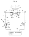
- the rotary motor 29 shown in Fig. 2 is used as a driving source of a mixing means, an optical path switching means, and a light amount adjusting means of an optical system in a light wave distance measuring system.
- the optical system primarily comprises a light projecting unit 40, a distance measuring optical unit 41, a photodetection unit 42, and a distance measuring circuit 43.
- the light projecting unit 40 comprises a semiconductor laser 44 for emitting a laser beam, an optical expander 48 for entering the laser beam emitted from the semiconductor laser 44 to an optical fiber 47 via lenses 45 and 46, a mixing means 50 provided between the lens 45 and the lens 46, and gradient index lenses 51 and 52 for entering the laser beam projected from the optical fiber 47 to an optical fiber 49 by changing a position angle.
- the rotary motor 29 is disposed in such manner that an optical path is aligned with the rotation shaft, and a phase plate 53 is mounted on the inner collar 33a of the rotary motor 29. Electric current is supplied to the coil 35, and the rotary cylinder 33 is rotated. As a result, the phase plate 53 is rotated, and a speckle pattern on the laser beam emitted from the semiconductor laser 44 can be eliminated.
- a prism 54 and an objective lens 55 are disposed on an optical axis of an incoming and outgoing distance measuring light.
- a light amount adjusting means 56 is disposed on an optical axis of the incident light to the prism 54
- an optical path switching means 59 is disposed on an optical axis of the reflection light from the prism 54.
- a splitting prism 57 is disposed on an entrance side of the light amount adjusting means 56
- a splitting prism 61 is disposed on an exit side of the optical path switching means 59, and these components make up the distance measuring optical unit 41.
- the photodetection unit 42 comprises an optical fiber 63 for guiding the laser beam projected from the splitting prism 61 toward a photodetection element 62, and condenser lenses 64 and 65 for converging the laser beam to the photodetection element 62.
- the distance measuring circuit 43 drives the semiconductor laser 44 to emit the light and calculates a distance to an object to be measured based on a photodetection signal from the photodetection element 62.
- the rotary motor 29 shown in Fig. 2 is used as the light amount adjusting means 56.
- a light amount adjusting plate 66 is mounted on the inner collar 33a of the rotary motor 29.
- the light amount adjusting plate 66 is an optical filter with its density varied along the circumferential direction, and a transmission amount of the laser beam is changed according to a rotating position of the light amount adjusting plate 66.
- the optical path switching means 59 comprises an optical path switching plate 67 mounted on the inner collar 33a of the rotary motor 29.
- the optical path switching plate 67 has two slits each in an arcuate shape. The two slits are deviated in positions from each other both in a radial direction and in a circumferential direction.
- a reflection distance measuring light 68' passes through one slit, while an inner reference light 69 passes through the other slit.
- the mixing means 50 is driven, and the phase plate 53 is rotated.
- the phase plate 53 is rotated.
- the speckle pattern of the laser beam can be eliminated.
- the laser beam projected from the optical fiber 49 is split to the distance measuring light 68 and the inner reference light 69 by the splitting prism 57.
- the light amount adjusting means 56 rotates the light amount adjusting plate 66, and the rotating position of the light amount adjusting plate 66 is selected so that light amounts of the receiving light at the photodetection element 62 are equalized with each other.
- the optical path switching plate 67 is rotated in a normal or reverse direction by the optical path switching means 59, and the reflected distance measuring light 68' and the inner reference light 69 to be entered to the photodetection unit 42 are switched over alternately.
- the distance to the object to be measured is calculated based on the photodetection signal of the reflected distance measuring light 68' and the inner reference light 69 received by the photodetection element 62.
- phase plate 53, the light amount adjusting plate 66, and the optical path switching plate 67 are rotated by the rotary motor 29. Further, the backlash of the bearing 34 is eliminated by the magnetic force between the flange unit 32a and the magnet 37.
- each of the phase plate 53, the light amount adjusting plate 66, and the optical path switching plate 67 can be approximately aligned with the optical axis of the laser beam. Therefore, the entire area of each of the phase plate 53, the light amount adjusting plate 66 and the optical path switching plate 67 can be used without any waste, and it is possible to design these components in a considerably compact size.
- the object to be rotated by the hollow type motor is not limited to the phase plate 53, the light amount adjusting plate 66, the optical path switching plate 67, etc., and it may be a moving part of a focusing mechanism.
- the hollow type motor it is possible to eliminate the use of gearing mechanisms for power transmission between a rotating body or a moving part and the motor, and this contributes to the simplified design of the structure.
- a rotating body is supported on a stator via a bearing, and a magnetic force in an axial direction acts on the rotating body between the rotating body and the stator, and prestress is given on the bearing by the magnetic force.
- prestress can be given to bearings in a system with simple structure. Even when there is one bearing, prestress can be given. Adequate prestress can be given without regard to the skill of the worker.
Landscapes
- Engineering & Computer Science (AREA)
- General Engineering & Computer Science (AREA)
- Power Engineering (AREA)
- Mechanical Engineering (AREA)
- Motor Or Generator Frames (AREA)
- Permanent Magnet Type Synchronous Machine (AREA)
- Support Of The Bearing (AREA)
- Iron Core Of Rotating Electric Machines (AREA)
Applications Claiming Priority (2)
| Application Number | Priority Date | Filing Date | Title |
|---|---|---|---|
| JP2000394768A JP4703845B2 (ja) | 2000-12-26 | 2000-12-26 | 小型回転モータ |
| JP2000394768 | 2000-12-26 |
Publications (2)
| Publication Number | Publication Date |
|---|---|
| EP1220421A2 true EP1220421A2 (de) | 2002-07-03 |
| EP1220421A3 EP1220421A3 (de) | 2003-08-20 |
Family
ID=18860344
Family Applications (1)
| Application Number | Title | Priority Date | Filing Date |
|---|---|---|---|
| EP01310518A Withdrawn EP1220421A3 (de) | 2000-12-26 | 2001-12-17 | Rotatorischer Motor kleinen Ausmasses |
Country Status (3)
| Country | Link |
|---|---|
| US (1) | US20020079767A1 (de) |
| EP (1) | EP1220421A3 (de) |
| JP (1) | JP4703845B2 (de) |
Cited By (2)
| Publication number | Priority date | Publication date | Assignee | Title |
|---|---|---|---|---|
| WO2004099622A1 (de) * | 2003-05-09 | 2004-11-18 | Leybold Vakuum Gmbh | Turbopumpe |
| WO2009035887A2 (en) * | 2007-09-10 | 2009-03-19 | Trimble Navigation Limited | Rotating laser transmitter |
Families Citing this family (5)
| Publication number | Priority date | Publication date | Assignee | Title |
|---|---|---|---|---|
| US8294311B2 (en) | 2006-03-06 | 2012-10-23 | Honda Motor Co., Ltd. | Electric motor and electric power steering apparatus |
| WO2013084270A1 (ja) * | 2011-12-09 | 2013-06-13 | 三菱電機株式会社 | 電動機 |
| JP2016192832A (ja) * | 2015-03-30 | 2016-11-10 | 日本電産株式会社 | モータ |
| KR101970453B1 (ko) | 2016-03-30 | 2019-04-18 | 밀워키 일렉트릭 툴 코포레이션 | 전동 공구용 브러시리스 모터 |
| JP6773900B2 (ja) * | 2016-10-10 | 2020-10-21 | エスゼット ディージェイアイ オスモ テクノロジー カンパニー リミテッドSZ DJI Osmo Technology Co., Ltd. | 3軸雲台および3軸雲台撮影装置 |
Citations (6)
| Publication number | Priority date | Publication date | Assignee | Title |
|---|---|---|---|---|
| JPH0271402A (ja) * | 1988-09-06 | 1990-03-12 | Canon Inc | 回転ドラム装置 |
| JPH08322192A (ja) * | 1995-05-29 | 1996-12-03 | Hitachi Ltd | ポリゴンミラー装置 |
| US5654597A (en) * | 1995-09-08 | 1997-08-05 | Kabushiki Kaisha Sankyo Seiki Seisakusho | Magnetic disk drive motor |
| JPH1132460A (ja) * | 1997-07-10 | 1999-02-02 | Copal Co Ltd | ブラシレスモータ |
| JPH11341734A (ja) * | 1998-05-22 | 1999-12-10 | Mitsubishi Electric Corp | ディスク形モータ |
| JP2000134892A (ja) * | 1998-08-19 | 2000-05-12 | Nippon Densan Corp | モ―タ |
Family Cites Families (7)
| Publication number | Priority date | Publication date | Assignee | Title |
|---|---|---|---|---|
| JP2579553Y2 (ja) * | 1989-10-31 | 1998-08-27 | 神鋼電機株式会社 | 無人車駆動用のブレーキ内蔵型電動機 |
| JPH0646552A (ja) * | 1991-01-30 | 1994-02-18 | Nippon Seiko Kk | 検出器付き電動機 |
| JPH0523782U (ja) * | 1991-08-30 | 1993-03-26 | 東京パーツ工業株式会社 | 径方向空隙型ブラシレスモータ |
| JP3123283B2 (ja) * | 1993-01-29 | 2001-01-09 | 松下電器産業株式会社 | ディスク駆動装置 |
| JPH08142471A (ja) * | 1994-11-22 | 1996-06-04 | Riso Kagaku Corp | 孔版印刷機の版胴装置 |
| JP3897435B2 (ja) * | 1998-02-26 | 2007-03-22 | 松下電器産業株式会社 | スピンドルモータ |
| JP2000050595A (ja) * | 1998-07-31 | 2000-02-18 | Nec Home Electron Ltd | ブラシレスモータ |
-
2000
- 2000-12-26 JP JP2000394768A patent/JP4703845B2/ja not_active Expired - Fee Related
-
2001
- 2001-12-17 US US10/023,380 patent/US20020079767A1/en not_active Abandoned
- 2001-12-17 EP EP01310518A patent/EP1220421A3/de not_active Withdrawn
Patent Citations (6)
| Publication number | Priority date | Publication date | Assignee | Title |
|---|---|---|---|---|
| JPH0271402A (ja) * | 1988-09-06 | 1990-03-12 | Canon Inc | 回転ドラム装置 |
| JPH08322192A (ja) * | 1995-05-29 | 1996-12-03 | Hitachi Ltd | ポリゴンミラー装置 |
| US5654597A (en) * | 1995-09-08 | 1997-08-05 | Kabushiki Kaisha Sankyo Seiki Seisakusho | Magnetic disk drive motor |
| JPH1132460A (ja) * | 1997-07-10 | 1999-02-02 | Copal Co Ltd | ブラシレスモータ |
| JPH11341734A (ja) * | 1998-05-22 | 1999-12-10 | Mitsubishi Electric Corp | ディスク形モータ |
| JP2000134892A (ja) * | 1998-08-19 | 2000-05-12 | Nippon Densan Corp | モ―タ |
Non-Patent Citations (5)
| Title |
|---|
| PATENT ABSTRACTS OF JAPAN vol. 014, no. 260 (P-1056), 5 June 1990 (1990-06-05) -& JP 02 071402 A (CANON INC), 12 March 1990 (1990-03-12) * |
| PATENT ABSTRACTS OF JAPAN vol. 1997, no. 04, 30 April 1997 (1997-04-30) -& JP 08 322192 A (HITACHI LTD), 3 December 1996 (1996-12-03) * |
| PATENT ABSTRACTS OF JAPAN vol. 1999, no. 05, 31 May 1999 (1999-05-31) -& JP 11 032460 A (COPAL CO LTD), 2 February 1999 (1999-02-02) * |
| PATENT ABSTRACTS OF JAPAN vol. 2000, no. 03, 30 March 2000 (2000-03-30) -& JP 11 341734 A (MITSUBISHI ELECTRIC CORP), 10 December 1999 (1999-12-10) * |
| PATENT ABSTRACTS OF JAPAN vol. 2000, no. 08, 6 October 2000 (2000-10-06) -& JP 2000 134892 A (NIPPON DENSAN CORP), 12 May 2000 (2000-05-12) * |
Cited By (6)
| Publication number | Priority date | Publication date | Assignee | Title |
|---|---|---|---|---|
| WO2004099622A1 (de) * | 2003-05-09 | 2004-11-18 | Leybold Vakuum Gmbh | Turbopumpe |
| WO2009035887A2 (en) * | 2007-09-10 | 2009-03-19 | Trimble Navigation Limited | Rotating laser transmitter |
| WO2009035887A3 (en) * | 2007-09-10 | 2009-04-30 | Trimble Navigation Ltd | Rotating laser transmitter |
| US7587832B2 (en) | 2007-09-10 | 2009-09-15 | Trimble Navigation Limited | Rotating laser transmitter |
| US7954246B2 (en) | 2007-09-10 | 2011-06-07 | Trimble Navigation Limited | Rotating laser transmitter |
| CN101784867B (zh) * | 2007-09-10 | 2013-05-22 | 天宝导航有限公司 | 旋转的激光发射器 |
Also Published As
| Publication number | Publication date |
|---|---|
| JP4703845B2 (ja) | 2011-06-15 |
| JP2002199648A (ja) | 2002-07-12 |
| EP1220421A3 (de) | 2003-08-20 |
| US20020079767A1 (en) | 2002-06-27 |
Similar Documents
| Publication | Publication Date | Title |
|---|---|---|
| US7667361B2 (en) | Electric motor and electronic apparatus | |
| US20120043832A1 (en) | Compact linear actuator with rotary mechanism | |
| KR100680152B1 (ko) | 감속기 일체형 액츄에이터 | |
| US6885116B2 (en) | Moving coil linear motor positioning stage with a concentric aperture | |
| US10260873B2 (en) | Surveying apparatus with positioning device | |
| CN106959508B (zh) | 紧凑旋转器和用于制造光束导向装置的方法 | |
| US8503104B2 (en) | Motor having small size and high output, and light amount adjustment device equipped with the motor | |
| EP1737111B1 (de) | Antriebsapparat | |
| KR20070039467A (ko) | 스테핑 모터 및 전자 기기 | |
| CN107678119B (zh) | 一种用于光学系统三稳态多视场变倍镜头切换的装置 | |
| EP1220421A2 (de) | Rotatorischer Motor kleinen Ausmasses | |
| KR100495352B1 (ko) | 모터 | |
| US6331741B1 (en) | Electromagnetic driving device | |
| JP2007104849A (ja) | 小型ステッピングモータ、それを有する駆動機構、及び、位置決め機構 | |
| CN110323919B (zh) | 一种基于正应力电磁驱动的微定位装置 | |
| US20080142332A1 (en) | Electromagnetic clutch device and method for manufacturing same | |
| JP2005202316A (ja) | 中空モータ一体型レンズ鏡筒 | |
| KR100699346B1 (ko) | 비접촉 회전 스테이지 | |
| KR20050093111A (ko) | 전자기력을 이용한 카메라 촛점조절장치 | |
| CN111774721A (zh) | 一种波片的光轴角度调节装置及其调节方法 | |
| JP4785432B2 (ja) | レンズ鏡筒 | |
| JP2006087174A (ja) | ステッピングモータ及びステッピングモータを用いた電子機器 | |
| JPH0686529A (ja) | 駆動装置及びカメラのシャッタ駆動装置及びカメラの鏡筒駆動装置 | |
| JPS60415A (ja) | レンズ駆動装置 | |
| JPH01138956A (ja) | ブラシレスモータの組立て方法 |
Legal Events
| Date | Code | Title | Description |
|---|---|---|---|
| PUAI | Public reference made under article 153(3) epc to a published international application that has entered the european phase |
Free format text: ORIGINAL CODE: 0009012 |
|
| AK | Designated contracting states |
Kind code of ref document: A2 Designated state(s): AT BE CH CY DE DK ES FI FR GB GR IE IT LI LU MC NL PT SE TR |
|
| AX | Request for extension of the european patent |
Free format text: AL;LT;LV;MK;RO;SI |
|
| PUAL | Search report despatched |
Free format text: ORIGINAL CODE: 0009013 |
|
| AK | Designated contracting states |
Designated state(s): AT BE CH CY DE DK ES FI FR GB GR IE IT LI LU MC NL PT SE TR |
|
| AX | Request for extension of the european patent |
Extension state: AL LT LV MK RO SI |
|
| RIC1 | Information provided on ipc code assigned before grant |
Ipc: 7H 02K 7/09 B Ipc: 7H 02K 5/173 A |
|
| AKX | Designation fees paid | ||
| REG | Reference to a national code |
Ref country code: DE Ref legal event code: 8566 |
|
| STAA | Information on the status of an ep patent application or granted ep patent |
Free format text: STATUS: THE APPLICATION IS DEEMED TO BE WITHDRAWN |
|
| 18D | Application deemed to be withdrawn |
Effective date: 20040221 |