EP1216068B1 - Revetements lubrifiants hydrophiles pour dispositifs medicaux - Google Patents
Revetements lubrifiants hydrophiles pour dispositifs medicaux Download PDFInfo
- Publication number
- EP1216068B1 EP1216068B1 EP00968484A EP00968484A EP1216068B1 EP 1216068 B1 EP1216068 B1 EP 1216068B1 EP 00968484 A EP00968484 A EP 00968484A EP 00968484 A EP00968484 A EP 00968484A EP 1216068 B1 EP1216068 B1 EP 1216068B1
- Authority
- EP
- European Patent Office
- Prior art keywords
- tubular member
- coating
- medical device
- poly
- stent
- Prior art date
- Legal status (The legal status is an assumption and is not a legal conclusion. Google has not performed a legal analysis and makes no representation as to the accuracy of the status listed.)
- Expired - Lifetime
Links
Images
Classifications
-
- A—HUMAN NECESSITIES
- A61—MEDICAL OR VETERINARY SCIENCE; HYGIENE
- A61L—METHODS OR APPARATUS FOR STERILISING MATERIALS OR OBJECTS IN GENERAL; DISINFECTION, STERILISATION OR DEODORISATION OF AIR; CHEMICAL ASPECTS OF BANDAGES, DRESSINGS, ABSORBENT PADS OR SURGICAL ARTICLES; MATERIALS FOR BANDAGES, DRESSINGS, ABSORBENT PADS OR SURGICAL ARTICLES
- A61L29/00—Materials for catheters, medical tubing, cannulae, or endoscopes or for coating catheters
- A61L29/08—Materials for coatings
- A61L29/085—Macromolecular materials
-
- A—HUMAN NECESSITIES
- A61—MEDICAL OR VETERINARY SCIENCE; HYGIENE
- A61F—FILTERS IMPLANTABLE INTO BLOOD VESSELS; PROSTHESES; DEVICES PROVIDING PATENCY TO, OR PREVENTING COLLAPSING OF, TUBULAR STRUCTURES OF THE BODY, e.g. STENTS; ORTHOPAEDIC, NURSING OR CONTRACEPTIVE DEVICES; FOMENTATION; TREATMENT OR PROTECTION OF EYES OR EARS; BANDAGES, DRESSINGS OR ABSORBENT PADS; FIRST-AID KITS
- A61F2/00—Filters implantable into blood vessels; Prostheses, i.e. artificial substitutes or replacements for parts of the body; Appliances for connecting them with the body; Devices providing patency to, or preventing collapsing of, tubular structures of the body, e.g. stents
- A61F2/95—Instruments specially adapted for placement or removal of stents or stent-grafts
- A61F2/962—Instruments specially adapted for placement or removal of stents or stent-grafts having an outer sleeve
- A61F2/966—Instruments specially adapted for placement or removal of stents or stent-grafts having an outer sleeve with relative longitudinal movement between outer sleeve and prosthesis, e.g. using a push rod
-
- A—HUMAN NECESSITIES
- A61—MEDICAL OR VETERINARY SCIENCE; HYGIENE
- A61M—DEVICES FOR INTRODUCING MEDIA INTO, OR ONTO, THE BODY; DEVICES FOR TRANSDUCING BODY MEDIA OR FOR TAKING MEDIA FROM THE BODY; DEVICES FOR PRODUCING OR ENDING SLEEP OR STUPOR
- A61M25/00—Catheters; Hollow probes
- A61M25/0043—Catheters; Hollow probes characterised by structural features
- A61M25/0045—Catheters; Hollow probes characterised by structural features multi-layered, e.g. coated
- A61M2025/0046—Coatings for improving slidability
Definitions
- This invention relates to a water soluble lubricious coating for a medical device such as a catheter assembly.
- Catheters are used in surgical procedures for insertion into blood vessels, urethra, or body conduits during such procedures as coronary angioplasty, stent delivery and placement for the opening of occluded or blocked blood vessels, for urological and reproductive surgeries, and to deliver biologically compatible fluids, such as radiologically opaque fluid for contrast x-rays to precise locations within the body.
- biologically compatible fluids such as radiologically opaque fluid for contrast x-rays
- catheters may be one of several different types including an over the wire, a single operator exchange or a fixed wire catheter assembly.
- Over the wire catheters may be used as guide catheters during coronary angioplasty, for instance.
- the guide catheter provides access to the area in which the stenosis or blockage may be found, and provides support for the treatment catheter which often includes a balloon dilatation system wherein a dilatation balloon is delivered to a site of stenosis in an artery and is used to alleviate the stenosis.
- the guide catheter is introduced over a guide wire through a previously placed introducer sheath and advanced through a blood vessel to the location of a stenosis.
- Other procedures may involve the introduction of other medical devices at precisely specific bodily locations including the delivery of stents, stent-grafts, grafts, vena cava filters, other expandable medical devices, and so forth.
- the catheters must be able to traverse tortuous pathways through blood vessels to the stenosis in a manner as atraumatic to the patient as possible. It is therefore desirable to make insertion through the patient in such a way to limit the insertion time and discomfort as much as possible.
- a common problem which occurs in catheter assemblies is friction or adhesion between various parts which periodically come into contact with one another during the medical procedure. For instance, friction can occur between the guide catheter and guide wire, between the introducer sheath and the guide catheter, or between the guide catheter and the balloon catheter, for instance, and may increase the difficulty of insertion, cause loss of catheter placement, and result in discomfort to the patient or damage to the vasculature. It is therefore desirable to reduce the friction due to the sliding between the various parts of the catheter assemblies.
- the materials from which catheters are produced are typically polymeric or metallic in nature, and in general, are inherently non-lubricious. When these non-lubricious materials come into contact, friction occurs. Medical device manufacturers have used various approaches to reduce the coefficient of friction between these surfaces.
- Hydrophobic coatings have been used to impart lubricity to medical devices including silicone based lubricants, glycerine or olive oil. These coatings have been known to wash off when exposed to an aqueous environment, lose initial lubricity rapidly, and lack abrasion resistance. Residual amounts of silicone have also been known to cause an inflammatory response in patients. The loss of lubricity can lead to discomfort during insertion into a patient, and damage to blood vessels and tissues due to frictional forces during insertion or removal of the device. Examples of silicone based lubricants include polysiloxanes and modified polysiloxanes. Often they include a polar group which may be an aminoalkyl or carboxyalkyl terminating group.
- U.S. Patent No. 5,084,315 to Karimi et al. issued January 28, 1992 discusses the problems with migration and beading.
- U.S. Patent No. 5,266,359 to Spielvogel issued November 30, 1993 describes a lubricating composition for a medical device which includes an emulsion of a noncuring polysiloxane, a surfactant and water.
- the surfactants are copolymers of polysiloxane and polyoxyethylene which are reactive and when cured, adhere to the surface. While Spielvogel teaches a method of application which does not utilize solvent, the problems associated with silicone based lubricants remain.
- U.S. Patent No. 5,272,012 to Opolski issued December 21, 1993 describes a method for providing a medical apparatus with a protective lubricious coating comprising providing a coating solution which contains a protective compound such as a urethane, a slip additive such as a siloxane, and optionally, a crosslinking agent for the protective compound such as polyfunctional aziridine, coating the solution onto a surface of a medical apparatus and allowing the coating to set.
- the protective compound binds the slip additive such that domains of the slip additive are exposed in the formed layer.
- the coating solution may also contain a crosslinking agent.
- the protective compound binds the slip additive such that domains of the slip additive are exposed in the formed layer.
- the coating solution may also contain a crosslinking agent.
- the protective compound preferably has functional moieties capable of crosslinking to other moieties within the protective compound and with moieties derived from the medical device.
- PTFE polytetrafluoroethylene
- Teflon ® polytetrafluoroethylene
- Hydrophilic compounds have also been used to impart lubricity in medical devices. Such compounds are biocompatible or blood compatible, and are more readily discharged from the body and have less of a tendency to cause tissue irritation. However, because of the hydrophilicity, It is also more difficult to retain such coatings on the surface of the medical device throughout the procedure.
- U.S. Patent No.5,509,899 to Fan et al. issued April 23, 1996 describes a lubricious coating for a medical balloon and catheter wherein the balloon is tightly wrapped and folded upon itself tortuously and tightly so that when in contact with each other for insertion into the body, the balloon is free of bridging and adhesion between abutting surfaces.
- the balloon has a base of a continuous polymeric surface which is expandable from a folded, wrapped configuration with surfaces touching each other.
- polymeric materials include Nylon, Selar ® , polyethylene terephthalate, polyethylene or similar materials. These materials may provide excellent balloon stock but ar not necessarily sufficiently lubricous to be used by themselves. Therefore, a lubricious, biocompatible hydrogel coating a disposed on the polymeric surface and a thin, lubricious, blood-compatible coating is disposed upon the hydrogel coating and adheres to it to prevent abutting surfaces of folded polymer surfaces from adhering to each other during inflation and also to prevent delamination of the hydrogel coating and/or rupture of the balloon.
- the blood-compatible coating is polyethylene glycol, methoxy polyethylene glycol or mixtures thereof having a molecular weight between about 100 and 20,000 grams per mole.
- U.S. Patent No. 5,849,368 to Hostettler et al. issued December 15, 1998 describes a process for rendering the surfaces of polymeric plastic or rubber materials, which are intrinsically non-polar or only slightly polar, polar or more polar, and hydrophilic, so that amine-containing functional groups, and ultimately, a durable tenaciously adhering, slippery polyurethane or polyurethane-urea hydrogel coating may subsequently be applied to the polymer surface.
- the process involves dual plasma-treatment of a polymeric plastic or rubber substrate material such that amine and amino groups are affixed to the substrate surface to make it more hydrophilic and reactive towards the terminal isocyanate groups of the polyurethane or polyurethane/urea prepolymers.
- the underlying problem of the invention is to provide a hydrophilic lubricant coating for medical devices, and in particular for catheter assemblies, to render inherently non-lubricious surfaces, lubricous, and a method for coating such devices which involves coating the inner surface a tubular member of medical device.
- WO 99/38545 A discloses a highly lubricious coating which strongly adheres to a medical device by using an intermediate polyisocyanate-based primer layer between the substrate and the lubricious coating.
- the technical problem underlying the present invention is to provide an highly lubricious coating which strongly adheres to a medical device using an alternative primer composition.
- This invention relates to a coating for rendering a medical device lubricious.
- the coating comprises pretreating primer composition, and a hydrophilic lubricious coating.
- the primer compound comprises substituents that are capable of adhering or bonding to, and improving the retention of the hydrophilic lubricant to the surface of the medical device.
- One such mechanism through which the primer compound may retain the hydrophilic polymer, is covalent bonding, or hydrogen bonding.
- This invention further relates to a medical device comprising at least one tubular member having an inner surface and an outer surface.
- the inner surface of the tubular member is at least occasionally subjected to contact with at least one second surface.
- the tubular member further comprises a hydrophilic coating disposed on the inner surface.
- the hydrophilic coating is present to inhibit the inner surface of the tubular member and the second surface from adhering to each other, and reduces the friction caused by movement between the two surfaces.
- the inner is first pretreated with the primer composition.
- the tubular member preferably comprises at least one thermoplastic polymer and the second surface preferably comprises a metal.
- the hydrophilic coating may be coated on the inner surface of the tube by injection, or coextrusion.
- An example of a medical device is a catheter assembly comprising at least one polymeric sheath having an inner surface and an outer surface.
- the inner surface of the first polymeric sheath is at least occasionally subjected to contact with at least one second surface, and comprises a water soluble coating disposed on the inner surface of the polymeric sheath.
- the hydrophilic coating is present to inhibit the inner surface and the second surface from adhering to each other.
- the polymeric sheath comprises at least one thermoplastic polymeric material.
- the second surface to which the inner surface of the polymeric sheath comes into contact may be a polymeric material or a metal.
- the inner surface of the polymeric sheath may first be coated with a primer of a crosslinkable composition which is readily wettable. This improves the uniformity and shelf stability of the lubricious coating.
- the water soluble lubricious coating may further comprise Vitamin E which acts as an antioxidant to further improve the shelf stability of the coating.
- a medical device is a stent deployment catheter assembly having at least one tubular member for retention and release of a stent.
- the tubular member may be a retractable sheath, or it may be at least one stent retaining sleeve.
- a hydrophilic lubricious coating is disposed on the inner surface of the tubular member in order to facilitate stent release by reducing the coefficient of friction between the tubular member and the stent.
- the lubricious coating of the present invention provides improved lubricity, eliminates migration problems associated with oil based lubricants and eliminates tissue reaction and irritation associated with oil based silicone lubricants.
- the diameter of the outer sheath of a medical device may be decrease thereby improving performance.
- Fig. 3 illustrates generally at (10) a tubular member which may be utilized in a medical device.
- the tubular member comprises an outer surface (12), and an inner surface (14), the inner surface forming a lumen (16).
- the lumen may be, for instance, a guide wire lumen for a catheter which is used in surgical procedures such as coronary angioplasty, stent delivery and placement for the opening of occluded or blocked blood vessels, for urological and reproductive surgeries, and to deliver biologically compatible fluids, such as radiologically opaque fluid for contrast x-rays to precise locations within the body.
- a water soluble lubricious coating (11) is disposed on the inner surface (14) of the tubular member (10).
- the coating reduces the coefficient of friction between the tubular member and any surface with which it comes into contact, and which are in a moving or sliding relationship with one another.
- the tubular member may be comprised of a polymeric material for instance, which is inherently non-lubricious.
- the tubular member may form any type of catheter including balloon catheters and stent delivery catheters, retractable sheaths or stent retaining sleeves for stent delivery catheters, guide wire lumens, pull wire lumens, and so forth.
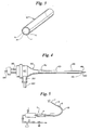
- Fig. 4 illustrates generally at 100 a catheter introducer having a tubular sheath (120) and a hub (140) attached to the proximal end (150) of tubular sheath (120).
- a branch conduit (200) and a locking sleeve (210) is provided to allow for, among other things, connections to saline solution or medicines and access to other medical procedures.
- a guide wire (220) is shown as it is often used with such devices as balloon angioplasty catheters.
- a dilator unit is shown at (180).
- Hydrophilic coating (110) is disposed on the inner surface of tubular sheath (120) for inserting and guiding a catheter into living tissue.
- a core wire may first be inserted through a hollow needle which is placed through the skin into the lumen of the desired blood vessel.
- the catheter introducer which comprises the tubular sheath (120), and a removable hollow stylet or dilator unit (180) may be advanced together over the core wire into the vessel.
- the core wire and dilator unit are then removed, leaving only the tubular sheath (120) of the catheter introducer present in the vessel.
- a catheter may then be advanced through the tubular sheath (120), into an artery for conventional purposes of angioplasty or any other desired purpose.
- the tubular sheath (120) may therefore come into contact with a core wire (220), dilator unit and catheter (180).
- the hydrophilic coating (110) on the inner surface of the tubular sheath (120) reduces the friction between the tubular sheath and the medical apparatus with which it comes into contact.
- These tubular sheaths may be utilized to maneuver medical devices such as catheter delivery devices for dilatation balloons, stents, stent-grafts, grafts, vena-cava filters, or other such devices to the desired location.
- Catheter sheath introducer (100) is typical of current, commercially available introducers but many modifications can be made.
- Proximal end (150) of sheath (120) may, for instance, be made of a rigid material while distal end (160) of sheath (120) may be made of flexible material for better control outside the body by the physician, for instance.
- Introducer type devices are known in the art and there are a vast number of different embodiments of such devices for which the present invention would find utility. Introducer type devices are illustrated in U.S. Patent No. 5,066,285 issued November 19, 1991 to Hillstead and in U.S. Pat. No. 5,466,230 issued November 14, 1995 to Davila.
- Fig. 5 illustrates generally at (5), one embodiment of a medical device used for passing a high-rotational-speed cutting tool into a vessel to remove abnormal deposits.
- the cutting tool (1) is mounted at the end of a flexible drive shaft which transmits torque from a torque-generating device (4), such as an electric or pneumatic motor.
- the drive shaft (2) is surrounded for most of its length by a guiding catheter.
- FIG. 1 Another embodiment in which the present invention may be utilized is in a surgical cutting device illustrated in U.S. Pat. No. 5,651,781 issued July 29, 1997 to Grace.
- the outer sheath in Grace houses a surgical cutting apparatus including a hollow cylindrical cutting blade member. The blade may be extended and retracted.
- the inner surface of the guiding catheter (3) may be coated with the lubricious coating of the present invention (15).
- Such devices are described in detail in U.S. Patent No. 4,445,509 issued May 1, 1984 and in 4,990,134 issued Feb. 5, 1991 , both to Auth.
- the coatings of the present invention may be incorporated into both over-the-wire (OTW) catheters and rapid-exchange (RX) or single operator catheters. These types of catheter construction are also used in stent deployment catheters.
- OW over-the-wire
- RX rapid-exchange
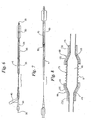
- Fig. 6 illustrates generally at (6) an over-the-wire catheter device specifically designed as a dilatation catheter for an inflatable balloon (50) which device comprises a manifold system designated generally at (30).
- the manifold (30) may further comprise a inflation luer (40).
- Guide wire (35) extends through the guide wire lumen (45) which is coated on the inner surface with the lubricious coating of the present invention (105), for reducing the wire movement frictional force, thereby improving the sliding relationship, between the guide wire (35) and the inner surface of the guide wire lumen (45).
- the guide wire lumen (45) encloses the guide wire (35), which aids in the navigation of the catheter (6) through the appropriate vessel.
- Fig. 7 illustrates generally at (7) a rapid exchange embodiment of a balloon catheter device which is similar in construction to the catheter device shown in Fig. 6 .
- the inner surface of the guide wire lumen (70), including the port (80) of the guide wire lumen, is coated with the lubricious coating of the present invention (95) to reduce wire movement friction when a guide wire is introduced into port (80), and is advanced through the guide wire lumen (70).
- the coatings of the present invention may also be utilized in stent deployment catheter systems as well as in angioplasty balloon catheters.
- balloons may be utilized to expand the stent once it is in position for deployment, or the stent may be self-expanding.
- Retractable sheaths may be utilized wherein the sheath is moved over the stent once it is in position. The retractable sheath may act both to protect the stent, as well as to prevent it from expanding prematurely. Once the sheath is retracted, the stent can expand.
- the coatings of the present invention may also be utilized as a coating on the inner surface of the retractable sheath, for instance.
- Stent deployment catheter devices including those having a retractable sheath, are described in U.S. Pat. No. 5,534,007 issued July 9, 1996 to St. Germain et al.
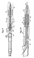
- Fig. 8 shows generally at (8) a sideview of a stent delivery catheter assembly.
- catheter (8) has an expandable portion or balloon (65).
- a stent (75) Disposed about the balloon (65) is a stent (75).
- Stent (75) may be any type of stent capable of being delivered by a stent delivery catheter, and may be self-expanding, or may be balloon expandable.
- the stent (75) is balloon expandable.
- stent retaining sleeves Attached to the catheter are a pair of stent retaining sleeves (66) and (68).
- the sleeves each include a first portion (a) and a second portion (b).
- first sleeve portions (a) overlay the ends of balloon (65) as well as the ends of stent (75), holding the stent in position.
- second sleeve portions (b) are fixedly attached to catheter (8).
- stent (75) releases from sleeve portions (66a) and (68a).
- Stent retaining sleeves (66) and (68) may be formed of many different polymeric materials. These polymeric materials are typically inherently non-lubricious. Stent (75) is typically a metal such as stainless steel, or a metal alloy of nickel and titanium, for instance. For reducing the coefficient of friction, and improving the sliding relationship between retaining sleeves (66) and (68), and stent (75), the lubricious coating of the present invention (115) is disposed on the inner surface of the pair of sleeves (66) and (68).
- Fig. 9 shows generally at (400) a catheter delivery device having a self-expanding stent (335) in a fully deployed position.
- the device generally comprises a proximal outer (410) which is characterized by a flexible tube which contains a pull wire lumen and optionally a guide wire lumen (315).
- the outer (410) may be comprised of a polymeric material such as high density polyethylene (HDPE) or Surlyn ® .
- the guide wire lumen (315) encloses a guide wire (320) which aids in the navigation of the catheter (305) through the appropriate vessel.
- the guide wire lumen (315) may be made of a flexible, but incompressible construction such as a polymer encapsulated braid or coil.
- the lubricious coating (325) of the present invention may be disposed on inner surface of the guide wire lumen (315) to reduce the coefficient of friction between the guide wire (320) and the guide wire lumen (315).
- This catheter delivery device has a distal sheath (340) which covers stent (335) when it is loaded.
- Fig. 9 illustrates distal sheath (340) in a fully retracted state and collapsible sheath (350) is in its compressed state thereby releasing the stent (335) to allow it to self-expand against the vessel wall (465).
- the hydrophilic coating (325) is disposed on the inner surface of the retractable sheath (340) to reduce the coefficient of friction between the retractable sheath (340) and the stent (335).
- the retractable distal sheath (340) which covers and contains the loaded stent (335), and holds the self-expanding stent (335) in its reduced delivery configuration, is connected to a retracting member (445).
- the retracting member (445) may be a rod, a cable, a tube which may also be used to transport fluids, a pull back wire, guide wire, or the like.
- the retracting member (445), e.g. a pull wire extends longitudinally within the proximal outer (410), optionally through a retracting member lumen (not shown), such as an HDPE, nylon, or polyether block amide (Pebax ® ) tube.
- the retracting member lumen extends longitudinally through the proximal outer (410), and houses the pull back wire (445).
- the inner surface of the retracting member lumen may have disposed on its inner surface thereof, the lubricious coating of the present invention for reducing the coefficient of friction between the pull back wire (445) and the retracting member lumen.
- Fig. 10 illustrates a rapid exchange embodiment of a catheter delivery device which is similar in construction to that found in Fig. 9 .
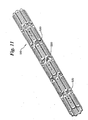
- Fig. 11 illustrates a tubular, flexible, self-expanding stent shown in Fig. 11 in an unexpanded state.
- the self-expanding stent shown in Fig. 11 may be used with either of the stent delivery catheters shown in Fig. 9 or Fig. 10 .
- the retractable sheath (340) is pulled back with pull back wire (445) to release the stent.
- the lubricious coating (325) of the present invention is disposed on the inner surface of the retractable sheath (340) to reduce the coefficient of friction between the retractable sheath (340) and the stent for a smooth, easy release.
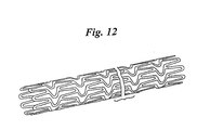
- Fig. 12 illustrates a balloon expandable stent which may be utilized with the balloon as shown in Fig. 8 .
- the lubricious coating of the present invention (115) is disposed on the inner surface of the pair of sleeves (66) and (68) to reduce the coefficient of friction between the stent retaining sleeves (66) and (68) and the stent for easier and smoother release of the stent.
- This type of stent is described in detail in U.S. Patent No. 5,843,120 .
- the hydrophilic lubricious coating (115) is a carboxylic acid, or alcohol, which has been converted from a nonhydrophilic polymeric material having, for instance, ester or amide groups capable of undergoing hydrolysis.
- Poly(maleic anhydride) may also be hydrolyzed to a carboxylic simultaneously with the polymeric material used for forming sleeves (66) and (68).
- the sleeves may be formed from a variety of organic high polymer materials such as polyamide, polyester, polyvinyl chloride, polystyrene, polyacrylate, polymethacrylate, polyacrylonitrile, polyacrylamide, polyethylene, polypropylene, polyurethane, polyvinyl acetate, silicone resins, polytetrafluoroethylene (PTFE) and copolymers and blends thereof.
- organic high polymer materials such as polyamide, polyester, polyvinyl chloride, polystyrene, polyacrylate, polymethacrylate, polyacrylonitrile, polyacrylamide, polyethylene, polypropylene, polyurethane, polyvinyl acetate, silicone resins, polytetrafluoroethylene (PTFE) and copolymers and blends thereof.
- PTFE polytetrafluoroethylene
- the inner layer of hydrophobic polyester or polyamide is then hydrolyzed either through acid or base catalysis, to a carboxylic acid, or alcohol.
- the result is a layer of hydrophilic lubricious coating.
- the sleeves are then cut from the tubular member resulting in a layered structure of hydrophilic coating on the inner surface and hydrophobic polymeric material on the outside.
- the coatings of the present invention may be utilized to improve the deployment of any of stents, stent-grafts, grafts or vena cava filters, or other such expandable medical devices, by coating the inner surface of the polymeric sheath to reduce the friction between the sheath and the stent.
- hydrophilic polymers which may be useful to the present invention including both non-reactive and reactive. Hydrophilicity may also be obtained by the reaction of polymers in the presence of water which then subsequently form water soluble moieties.
- the hydrophilic lubricants useful herein include polyalkylene glycols, alkoxy polyalkylene glycols, copolymers of methylvinyl ether and maleic acid, poly(vinylpyrrolidone), poly(acrylamide) including poly(N-alkylacrylamide), poly(acrylic acid), poly(saccharide), poly(vinyl alcohol), poly(ethyleneimine), polyamides, methyl cellulose, carboxymethylcellulose, polyvinylsulfonic acid, heparin, dextran, modified dextran, chondroitin sulphate, lecithin, and so forth.
- the polymers are typically chain-structured, non-crosslinked and water soluble having a hydrophilic group such as -OH, -CONH 2 , -COOH, -NH 2 , -COO-, -SO 3 , -NR 3 + and so forth where R is alkyl or hydrogen.
- Derivatives of these polymers may also be utilized providing, even if they are not water soluble, that they are still of a structure which is capable of being hydrated, or is dispersible in water.
- Examples include esterified polymers, salts, amides, anhydrides, halides, ethers, hydrolyzates, acetals, formals, alkylols, quaternary polymers, diazos, hydrazides, sulfonates, nitrates, and ion complexes which are obtained by condensation, addition, substitution, oxidation, or reduction reactions of the above mentioned water soluble polymers.
- polymers crosslinked with substances having more than one reactive functional group such as diazonium, azide isocyanate, acid chloride, acid anhydride, imino carbonate, amino, carboxyl, epoxy, hydroxyl and aldehyde groups.
- Further polymers include those copolymerized with vinyl, acrylic acid, methacrylic acid, diene compounds, and so forth.
- a preferred class of hydrophilic lubricants are polyalkylene glycols or alkoxy polyalkylene glycols which have the following general formula: or R1 and R2 may be the same or different and can be H or an alkyl group having 1 to about 6 carbon atoms; x is from 2 to about 500; and y is from 0 to about 100.
- polyalkylene glycols and alkoxy polyalkylene glycols may also contain functional groups such as, for example, hydroxyl, sulfur, nitrogen or oxygen.
- the water soluble lubricants are copolymers of polyalkylene glycols or alkoxy polyalkylene glycols.
- specific examples of such copolymers include Pluronic ® 31R1 surfactant, a polyoxypropylene/polyoxyethylene block copolymer available from BASF Corp. in Mount Olive, NJ and Cremophor ® EL 35, an ethoxylated castor oil (PEG 35 Castor Oil) or polyoxyethyleneglycerol triricino available from BASF Corp. in Wyandotte, MI.
- the lubricious coatings can be formed from hydrophobic compounds which can be converted to a lubricious hydrophilic compound through a chemical reaction such as hydrolysis, for instance. The conversion may take place once the coating process is complete.
- examples of such compounds include those compounds having pendant ester or amide groups, such as, for instance, esters such as poly(acrylates), poly(meth)acrylates, poly(vinyl esters), poly(maleates), poly(fumerates), polyamides, poly(acrylamides), and copolymers and terpolymers thereof, and so forth.
- esters such as poly(acrylates), poly(meth)acrylates, poly(vinyl esters), poly(maleates), poly(fumerates), polyamides, poly(acrylamides), and copolymers and terpolymers thereof, and so forth.
- the poly(acrylic), poly(methacrylic) or polymaleic esters, and the polyamides or poly(acrylamides) may be converted to carboxylic acids by hydrolysis
- Hydrolysis may be basic or acidic, and heat may be added to increase the rate of reaction.
- Esters are hydrolyzed reversibly in the presence of acid or irreversibly in the presence of base. The use of a large excess of water in the acid-catalyzed reaction favors hydrolysis.
- Vinyl esters may also be converted to an alcohol through saponification using an alkali-metal hydroxide which forms the alcohol and the metal salt of the acid. While most of these materials are hydrophobic, some are hydrophilic and can be hydrolyzed as well.
- R, R 1 , R 2 and R 3 can each independently be hydrogen or alkyl having from one to four carbon atoms and n is an integer.
- the molecular weight range for these polymers is broad and may be from about 800 to about 400,000 g/mole.
- the molecular weights are from about 1,000 to about 20,000 g/mole.
- the main benefit of utilizing a water soluble lubricant is that it will quickly dissolve into the blood stream and move out of the body within a short period, reducing the likelihood of inflammation and restenosis.
- the silicone based lubricants have been known to cause tissue reaction, irritation and inflammation in patients.
- the water soluble lubricants of the present invention exhibit excellent lubricity and friction reduction. Oil based lubricants such as silicones, glycerine or olive oil tend to bead and migrate from the coated surface, reducing the benefits of the lubricant which may result in a surface that does not have as much lubricity and friction reduction. Furthermore, the lubricant then may move into the bloodstream where it has less compatibility than the water soluble lubricants resulting in irritation of tissue.
- the solvents are polar and include alcohols, glycols, water and so forth. Specific examples include ethanol, methanol, isopropyl alcohol (IPA), stearyl alcohol, ethylene glycol, propylene glycol, glycerin, water, methylethyl ketone (MEK) and so forth.
- IPA isopropyl alcohol
- MEK methylethyl ketone
- isopropanol and mixtures of isopropanol with other solvents is preferred.
- the lubricious coating may also contain Vitamin E which acts as an antioxidant. This improves the long term stability of the coating by reducing the degradation, allowing longer shelf stability. It is important that the lubricity of the medical device remains for an extended period to allow for the fact that such devices may not be used for a period of time. Vitamin E is sold in as a liquid and in itself has limited lubricious qualities and does not improve the overall lubricity of the coating. Vitamin E may be purchased from Sigma. Preferably, it will have a 95% purity or greater.
- the polymeric surface to be coated with the water soluble lubricants of the present invention will be surface primed with a crosslinkable primer composition.
- the hydrophilic coating is relatively soluble in bodily fluids and can be easily washed away or flushed from the surface. Premature departure of the hydrophilic coating from the surface of the device may lead to insufficient lubricity. It is therefore desirable to retain the hydrophilic coating on the surface for a period of time.
- the primer acts to promote adhesion of the hydrophilic coating to the surface of the device thereby preventing premature removal of the lubricious coating.
- the crosslinkable primer is generally hydrophobic in nature but has some substituents attached thereon that make it attractive to a hydrophilic polymer. It is surmised that the hydrophilic polymer adheres through hydrogen bonding. Therefore, any groups which participate in hydrogen bonding with the hydrophilic polymer will improve retention on the surface of the medical device.
- the crosslinkable compounds include those having hydrophilic functionality such as amine, amide, carboxyl, hydroxyl, thiol, phosphorous, and so forth.
- the reactive primer is oriented in such a way that these functional groups provide a mechanism by which the water soluble lubricious coating may better adhere to the surface to be lubricated, thereby preventing the water soluble lubricious coating from immediately, or in any event prematurely, washing away upon exposure to bodily fluids, for instance.
- Crosslinkable chemical compounds used in the present invention include titanate and zirconate coupling agents, such as isopropyl triisostearoyl titanate and neopentyl diallyl oxytrineodecanoyl zirconate. Both are available in liquid form. These crosslinkable agents are often supplied in a solution with heptane and its mixtures, being a preferred solvent. These agents may be put in solution alone, and then coated on the medical device prior to application of the hydrophilic coating, or they may be put in solution with the hydrophilic coating by using a cosolvent mixture, therefore eliminating one step in the coating process.
- titanate and zirconate coupling agents such as isopropyl triisostearoyl titanate and neopentyl diallyl oxytrineodecanoyl zirconate. Both are available in liquid form.
- These crosslinkable agents are often supplied in a solution with heptane and its mixtures, being a preferred solvent. These agents may be put
- the lubricious coatings of the present invention may be utilized on any medical device wherein it is desirable to reduce the surface friction or adhesion between two surfaces, whether it be polymeric to polymeric surface or polymeric to metallic surface.
- medical devices include, but are not limited to, over the wire catheters, single operator exchange or rapid exchange catheters, fixed wire catheters, IV or over the needle catheters, introducing sheaths, Rotablator ® , non-invasive surgical cutting devices, needles, blades, cannulas, any stent deployment device, and so forth.
- Catheters may be utilized to deploy an medical devices such as a stent, stent-graft, graft or vena cava filter to a precise location within a bodily lumen. Such deployed devices may be expandable or self-expandable devices. Over the wire catheters and rapid exchange catheters are discussed in detail in U.S. Patent No. 5,534,007 to St. Germain et al. issued July 9, 1996 .
- the present invention is useful on any surface for which it is desired to reduce friction between that surface and another, second surface.
- the coating is utilized on a catheter assembly in which there is typically a first tubular member or outer sheath which forms a lumen within which other tubular members or metal wires may be housed.
- the outer sheath is made up of a distal portion and a proximal portion.
- the tubular member will be a thermoplastic polymeric material which is capable of being molded into a shaped article such as a hollow tube.
- Such materials may include, but are not limited to, homopolymers, copolymers and terpolymers of ethylene; homopolymers, copolymers and terpolymers of propylene; polyesters; polyamides; polyurethanes; vinylic copolymers; block copolymers; and so forth.
- Hytrel ® ), Pebax ® , Surlyn ® , polyethylene terephthalate, polytetrafluoroethylene, polyvinyl chloride, polyurethanes, polyetherurethanes, polyesterurethanes, polyurethane ureas, polyurethane siloxane block copolymers, polyethylene, polypropylene or other similar extrudable thermoplastic, polymeric materials, or composites thereof may be utilized in the present invention.
- a catheter may have a proximal end and a distal end, each of which is formed from a different material. It may, therefore, be two separate sheaths which are adhered together.
- the proximal end of the tubular sheath is typically made of a more flexible material than is the distal end.
- the entire sheath, both proximal and distal end may be comprised of one material thereby forming a continous sheath. Such materials are typically inherently non-lubricious.
- the lumen of the outer sheath may comprise other tubular members which may serve to transport fluids, to protect guide wires or pull back wires, or the lumen may contain the guidewires or pull back wires themselves. Both during deployment of the medical device, and during retraction, it will be necessary to reduce the adhesion or friction which may be present between the materials.
- the outer sheath may be a flexible tube which contains a pull wire lumen and a guide wire lumen.
- the outer sheath is comprised of high density polyethylene (HDPE) or Surlyn ® .
- the outer sheath may enclose an optional guide wire lumen which is made of a flexible, but incompressible construction, such as a polymer encapsulated braid or coil which may be comprised of stainless steel or nitinol encased in a polymer such as a polyimide, HDPE, teflon or polyurethane.
- the lubricious coating of the present invention may be coated on both the inner surface of the outer sheath to reduce adhesion and friction between the guide wire lumen and the inner surface of the outer sheath, and on the inner surface of the guide wire lumen to reduce friction between the inner surface of the guide wire lumen and the guide wire itself.
- a tubular member having an inner surface and an outer surface and comprised of a thermoplastic polymeric material slides over a metal wire.
- the inner surface of the tubular member is coated with the lubricious coating of the present invention to reduce the adhesion and friction between the polymeric material and the metal when the metal wire is moved through the polymeric tube.
- the lubricious hydrophilic coating of the present invention it is possible to achieve up to a 65%, preferably at least about 30% and more preferably at least about 50%, reduction in force for the wire movement friction.
- a further benefit to utilizing the coating of the present invention is that the radius of the tubular members may be reduced, thereby reducing the profile of the catheter and improving the traceability.
- the surface of the tubular member may be primed or pre-treated with the reactive compound having hydrophobic and hydrophilic functionality thereon including those compounds having groups such as amine, amide, carboxyl, hydroxyl, and so forth. These groups are available on the surface for "binding" the water soluble lubricious coating in such a way that the coating will not wash away from the surface of the article.
- This reactive primer provides a uniform wettable surface which facilitates adherence of the lubricious coating along the elongated interior surface of the tube.
- the reactive compound may be silane or silicone oligomer which forms a crosslinked coating on the tubular surface upon application and drying.
- One method of treating priming or treating the inner surface of a tubular member involves a flush method whereby a solution of the lubricious coating is connected to a port of the tube via a syringe, and solution is thereby injected and passes through the entire tube.
- the silicone compound is dissolved in a solvent, preferably heptane or the like in a concentration of about 0.1 % to about 10% of the crosslinkable compound, preferably from about 0.2% to about 5% concentration based on weight/volume.
- the excess solution trapped in the tubular member is removed through air pressure or nitrogen at 1-2 atmospheres.
- the crosslinking reaction is then carried out with heat at temperatures of about 30° C to about 80° C, preferably from about 40° C to about 65° C and even more preferably at temperatures of about 45° C to about 55° C.
- the lubricious coating is prepared by making a solution of the water soluble lubricant in solvent at a concentration of about 1% to about 30% of the lubricant.
- Antioxidant may be added in an amount of about 0.01% to about 1.0% and preferably about 0.1% to about 0.5%.
- a preferable solvent is an alcohol such as isopropanol, methanol or ethanol.
- the lubricious coating may then be applied utilizing a flush method.
- a syringe may be connected to a port of the tubular member, the solution injected via a syringe or the like until approximately 3 mls passes through the tube.
- the lubricated tube is cleaned using air pressure or nitrogen at 1-2 atmospheres for at least 10 minutes, thereby removing excess solution.
- the lubricious coating may be coextruded with the material from which the tubular member is being formed, such as polyethylene, Pebax ® , polyester elastomer, and so forth, thereby forming a coating in this fashion. It is preferable that the lubricious coating be coextruded on the inside surface of the now dual layer tube.
- a hydrophobic ester is coextruded on the inside of the tubular member.
- the ester is subsequently hydrolyzed using an acid or base and heat, to form the hydrophilic lubricious coating on the inner surface of the tubular member.
- crosslinkable silicones as primers as an alternative to the titanates and zirconates of the present invention.
- a solution of crosslinkable silicone primer was prepared by dissolving 0.5g of Silastic ® MDX4 from Dow Coming Chemicals in Midland, Mich. in about 99.7 milliliters of heptane in a 100 ml column (concentration of 0.5% based on weight/volume).
- Silastic ® MDX4 has a 50% concentration in a pseudocumene and isopropanol mixture as purchased.
- Heptane was purchased from Aldrich chemical in anhydrous form >99% purity with a water content of ⁇ 0.005%.
- a solution of crosslinkable silicone was prepared by dissolving about 0.2 g of MDX4 in heptane.
- the MDX4 was weighed in a 100 ml column with a cap and heptane is added to total 100 ml (about 0.2% concentration based on weight/volume).
- the inner surface of a catheter was treated with the MDX4 using a flush method.
- a 20 ml glass syringe containing 10 ml of MDX4 solution was connected with the port of the catheter and 3ml of solution is injected and passed through the whole catheter. The syringe was then moved to the other port.
- the treated catheter was then cleaned by air pressure or nitrogen at 1-2 atmospheres for in excess of 10 minutes to remove the excess solution trapped in the catheter.
- the cleaned catheter was then heated in an oven at 55°C for at least 4 hours to carry out the crosslinking reaction.
- a solution of lubricant was prepared by dissolving 20g of Pluronic ® 31R1, polyoxypropylene-polyoxyethylene block copolymer from BASF and 0.02g Vitamin E from Sigma in isopropanol (IPA) until a total of 100 ml is achieved resulting in a 20% weight/volume concentration.
- the IPA may be purchased from Aldrich Chemicals with >99% purity and a water content of ⁇ 0.005%.
- a 10% solution of lubricant was prepared by dissolving 10g of Pluronic ® 31R1, 0.02g Vitamin E in IPA until the total is 100 ml.
- a 20% solution of Cremophor ® EL 35, ethoxylated castor oil, from BASF Corp. was prepared by dissolving 20g of Cremophor® and 0.02g Vitamin E in IPA until the total is 100 ml.
- a 20% solution of Cremophor ® EL 35, ethoxylated castor oil, from BASF Corp. was prepared by dissolving 20g of Cremophor® and 0.02g Vitamin E in IPA until the total is 100 ml.
- the inner surface of a catheter was lubricated using the flush method by connecting a 20 ml glass syringe containing about 10 ml lubricant solution to the port of the catheter, injecting the lubricant solution and passing it through the tip until 3 ml of solution was used.
- the catheter was then cleaned using air pressure or nitrogen gas at about 1-2 atmospheres for in excess of 10 minutes to remove any excess solution trapped in the catheter.
- the catheter is then heated to about 55°C for about 1-2 hours and is conditioned over night at ambient temperature to ensure complete drying of the catheter.
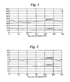
- a high density polyethylene balloon catheter with a lumen having an inner diameter of 0.0167" (0.0424 cm) was pretreated with Primer 1 followed with Lubricious Coating 3, above.
- the lumen was then flushed with 3 mls of saline using a syringe.
- a stainless steel wire having an outer diameter or 0.0162" (0.0411 cm) was inserted and the wire movement force was measured using a computer controlled force test machine with a special fixture to model the tortuous shape of the coronary vessel. The wire was pulled at a rate of 8.25 mm/sec over a minimum of 300 mm. The test was done at ambient temperature.
- the force required to pull the wire through the catheter lumen was measured on the test specimen and on a control catheter which had no hydrophilic coating.
- the force required on the uncoated specimen was 250 g while that on the coated catheter was 85 g. A force reduction of 65% was noted.
- Fig. 1 illustrates the force required for the uncoated control catheter and for Example 1.
- a high density polyethylene balloon catheter having a lumen with an inner diameter of 0.0169" (0.0429 cm) was pretreated with Primer 2 followed by Lubricious Coating 1.
- the same procedure utilizing the same size wire as in Example 1 was followed.
- the uncoated catheter had a wire movement force of 60 g while the coated catheter had a wire movement force of 30 g. A 50% force reduction was achieved.
- Fig. 2 illustrates the force required for the uncoated control catheter and for Example 2.
- a polyethylene tube with a length of 75 mm, an inner diameter of 1.27 mm, an outer diameter of 1.31 mm and a wall thickness of 0.2 mm was first coated with Primer 3. The tube was dried in an oven at 55° C for 2 hours. The tube was then coated a second time with Lubricious Coating 5 and dried in an oven at 55° C for over 2 hours to ensure complete drying.
- a stainless steel rod having a length of 75 mm and a diameter of 1.27 mm was inserted into the coated polyethylene tube to a length of 25 mm.
- a control sample was prepared by coating a polyethylene tube as described above with Primer 3 and followed by a 6% concentration of DC 360 silicone lubricant. A stainless steel rod was also inserted into this tube.
Claims (14)
- Dispositif médical comprenant au moins un élément tubulaire (10) présentant une surface intérieure (16) et une surface extérieure (12), ladite surface intérieure (16) dudit élément tubulaire (10) étant au moins occasionnellement soumise au contact avec au moins une seconde surface, ledit élément tubulaire (10) étant recouvert d'un revêtement sur ladite surface intérieure par le procédé consistant à :a) prétraiter ladite surface intérieure dudit élément tubulaire à l'aide d'une composition primaire réticulable dans laquelle le composant réticulable est sélectionné parmi le groupe constitué des titanates et des zirconates ; etb) recouvrir ladite surface intérieure dudit élément tubulaire prétraité d'un revêtement lubrifiant hydrophile,dans lequel ledit revêtement hydrophile est présent pour réduire le frottement entre la surface intérieure dudit élément tubulaire et ladite seconde surface causé par le mouvement.
- Dispositif médical selon la revendication 1, dans lequel ledit élément tubulaire comprend un matériau polymère thermoplastique.
- Dispositif médical selon la revendication 1, dans lequel ledit élément tubulaire comprend au moins un matériau sélectionné dans le groupe constitué des homopolymères, des copolymères et des terpolymères d'éthylène ; des homopolymères, des copolymères et des terpolymères de propylène ; des polyesters ; des polyamides ; des polyuréthanes ; des copolymères vinyliques ; des copolymères bloc ; des ionomères de copolymères bloc ; et des mélanges de ceux-ci.
- Dispositif médical selon la revendication 1, dans lequel ledit revêtement hydrophile comprend au moins un matériau sélectionné dans le groupe constitué des polyalkylène glycols ; alkoxy polyalkylène glycols ; polysaccharides ; polyvinylpyrrolidones ; alcools polyvinyliques ; acide polyacryliques ; polyacrylamides ; anhydrides polymaléiques ; et des copolymères et mélanges de ceux-ci.
- Dispositif médical selon la revendication 1, dans lequel ladite surface intérieure est recouverte d'un revêtement en injectant un composé hydrophobe dans ledit élément tubulaire, formant ainsi un revêtement hydrophobe sur ladite surface intérieure dudit élément tubulaire et en convertissant ensuite la surface dudit revêtement hydrophobe en un revêtement hydrophile.
- Dispositif médical selon la revendication 5, dans lequel ledit composé hydrophobe est un polymère sélectionné dans le groupe constitué des polyacrylates, des polyméthacrylates, des esters polyvinyliques, des esters de polymaléate, des esters de polyfumarate, des polyamides, des polyacrylamides, et les copolymères, terpolymères et mélanges de ceux-ci.
- Dispositif médical selon la revendication 5 dans lequel ledit polymère hydrophobe est converti en un acide carboxylique par hydrolyse.
- Dispositif médical selon la revendication 1, dans lequel ledit revêtement lubrifiant hydrophile comprend en outre de la vitamine E.
- Dispositif médical selon la revendication 1, dans lequel ledit dispositif médical est un ensemble de cathéter.
- Dispositif médical selon la revendication 9, dans lequel ledit ensemble de cathéter est sélectionné dans le groupe constitué des cathéters à fil fixe, des cathéters sur fil-guide et des cathéters à remplacement rapide.
- Dispositif médical selon la revendication 9, dans lequel ledit ensemble de cathéter est un cathéter de déploiement de stent.
- Dispositif médical selon la revendication 11, dans lequel ledit cathéter de déploiement de stent est adapté à un stent, un stent-greffe, une greffe ou un filtre de veine cave.
- Procédé de prétraitement de la surface intérieure d'un dispositif médical comprenant les étapes consistant à :a) coextruder un premier polymère hydrophile simultanément à un second polymère hydrophile dans lequel lesdits premier et second polymères forment un élément tubulaire présentant une première surface hydrophobe intérieure constituée du premier polymère hydrophobe et une seconde surface hydrophobe extérieure constituée dudit second polymère ; etb) prétraiter la surface intérieure dudit élément tubulaire à l'aide d'une composition primaire réticulable dans laquelle ledit composant réticulable est sélectionné dans le groupe constitué des titanates et des zirconates, et revêtir ladite première surface hydrophobe intérieure dudit élément tubulaire prétraité sur une surface hydrophile lubrifiante.
- Procédé selon la revendication 13, dans lequel ledit premier polymère hydrophobe est converti en une surface lubrifiante hydrophile par hydrolyse.
Priority Applications (2)
| Application Number | Priority Date | Filing Date | Title |
|---|---|---|---|
| EP20140172757 EP2818188A1 (fr) | 1999-09-28 | 2000-09-28 | Revêtements hydrophiliques pour dispositifs médicaux |
| EP08000925.1A EP1917986B1 (fr) | 1999-09-28 | 2000-09-28 | Revêtements hydrophiles pour dispositifs médicaux |
Applications Claiming Priority (3)
| Application Number | Priority Date | Filing Date | Title |
|---|---|---|---|
| US406987 | 1999-09-28 | ||
| US09/406,987 US6458867B1 (en) | 1999-09-28 | 1999-09-28 | Hydrophilic lubricant coatings for medical devices |
| PCT/US2000/026787 WO2001023015A1 (fr) | 1999-09-28 | 2000-09-28 | Revetements lubrifiants hydrophiles pour dispositifs medicaux |
Related Child Applications (2)
| Application Number | Title | Priority Date | Filing Date |
|---|---|---|---|
| EP20140172757 Division EP2818188A1 (fr) | 1999-09-28 | 2000-09-28 | Revêtements hydrophiliques pour dispositifs médicaux |
| EP08000925.1A Division EP1917986B1 (fr) | 1999-09-28 | 2000-09-28 | Revêtements hydrophiles pour dispositifs médicaux |
Publications (2)
| Publication Number | Publication Date |
|---|---|
| EP1216068A1 EP1216068A1 (fr) | 2002-06-26 |
| EP1216068B1 true EP1216068B1 (fr) | 2008-02-27 |
Family
ID=23610156
Family Applications (3)
| Application Number | Title | Priority Date | Filing Date |
|---|---|---|---|
| EP20140172757 Withdrawn EP2818188A1 (fr) | 1999-09-28 | 2000-09-28 | Revêtements hydrophiliques pour dispositifs médicaux |
| EP00968484A Expired - Lifetime EP1216068B1 (fr) | 1999-09-28 | 2000-09-28 | Revetements lubrifiants hydrophiles pour dispositifs medicaux |
| EP08000925.1A Expired - Lifetime EP1917986B1 (fr) | 1999-09-28 | 2000-09-28 | Revêtements hydrophiles pour dispositifs médicaux |
Family Applications Before (1)
| Application Number | Title | Priority Date | Filing Date |
|---|---|---|---|
| EP20140172757 Withdrawn EP2818188A1 (fr) | 1999-09-28 | 2000-09-28 | Revêtements hydrophiliques pour dispositifs médicaux |
Family Applications After (1)
| Application Number | Title | Priority Date | Filing Date |
|---|---|---|---|
| EP08000925.1A Expired - Lifetime EP1917986B1 (fr) | 1999-09-28 | 2000-09-28 | Revêtements hydrophiles pour dispositifs médicaux |
Country Status (9)
| Country | Link |
|---|---|
| US (1) | US6458867B1 (fr) |
| EP (3) | EP2818188A1 (fr) |
| JP (1) | JP2003510134A (fr) |
| AT (1) | ATE387225T1 (fr) |
| AU (1) | AU7838700A (fr) |
| CA (1) | CA2382108C (fr) |
| DE (1) | DE60038180T2 (fr) |
| ES (1) | ES2299435T3 (fr) |
| WO (1) | WO2001023015A1 (fr) |
Families Citing this family (114)
| Publication number | Priority date | Publication date | Assignee | Title |
|---|---|---|---|---|
| US7238197B2 (en) | 2000-05-30 | 2007-07-03 | Devax, Inc. | Endoprosthesis deployment system for treating vascular bifurcations |
| US7686846B2 (en) | 1996-06-06 | 2010-03-30 | Devax, Inc. | Bifurcation stent and method of positioning in a body lumen |
| US8728143B2 (en) | 1996-06-06 | 2014-05-20 | Biosensors International Group, Ltd. | Endoprosthesis deployment system for treating vascular bifurcations |
| US7820734B2 (en) * | 1998-10-07 | 2010-10-26 | Tyco Healthcare Group Lp | Antimicrobial lubricious coating |
| US6503556B2 (en) * | 2000-12-28 | 2003-01-07 | Advanced Cardiovascular Systems, Inc. | Methods of forming a coating for a prosthesis |
| US6648863B2 (en) * | 2000-09-20 | 2003-11-18 | Scimed Life Systems, Inc. | Apparatus and methods for treating the urinary bladder |
| US20050226993A1 (en) * | 2000-10-03 | 2005-10-13 | Nawrocki Jesse G | Medical devices having durable and lubricious polymeric coating |
| US8632845B2 (en) * | 2000-12-28 | 2014-01-21 | Abbott Cardiovascular Systems Inc. | Method of drying bioabsorbable coating over stents |
| JP4499310B2 (ja) * | 2001-04-12 | 2010-07-07 | 経憲 武井 | 手術器具 |
| US20030109865A1 (en) * | 2001-12-12 | 2003-06-12 | Megadyne Medical Products, Inc. | Utilization of a multi-character material in a surface coating of an electrosurgical instrument |
| US7713272B2 (en) | 2001-12-20 | 2010-05-11 | Ethicon, Inc. | Bioabsorbable coatings of surgical devices |
| US7300534B2 (en) * | 2002-01-15 | 2007-11-27 | Boston Scientific Scimed, Inc. | Bonds between metals and polymers for medical devices |
| US7041088B2 (en) * | 2002-10-11 | 2006-05-09 | Ethicon, Inc. | Medical devices having durable and lubricious polymeric coating |
| DE60231843D1 (de) | 2002-11-08 | 2009-05-14 | Jacques Seguin | Endoprothese für gefässgabelung |
| US20090165784A1 (en) * | 2007-12-28 | 2009-07-02 | Tyco Healthcare Group Lp | Lubricious intubation device |
| US20040153006A1 (en) * | 2003-02-03 | 2004-08-05 | Scimed Life Systems, Inc. | Intracorporeal devices with ionomeric polymer sleeves |
| US20040241023A1 (en) * | 2003-05-27 | 2004-12-02 | Pinkerton Harry E. | Positive displacement pump having piston and/or liner with vapor deposited polymer surface |
| US8541051B2 (en) * | 2003-08-14 | 2013-09-24 | Halliburton Energy Services, Inc. | On-the fly coating of acid-releasing degradable material onto a particulate |
| US7824392B2 (en) | 2003-08-20 | 2010-11-02 | Boston Scientific Scimed, Inc. | Catheter with thin-walled braid |
| US8500792B2 (en) | 2003-09-03 | 2013-08-06 | Bolton Medical, Inc. | Dual capture device for stent graft delivery system and method for capturing a stent graft |
| US20080264102A1 (en) | 2004-02-23 | 2008-10-30 | Bolton Medical, Inc. | Sheath Capture Device for Stent Graft Delivery System and Method for Operating Same |
| US9198786B2 (en) | 2003-09-03 | 2015-12-01 | Bolton Medical, Inc. | Lumen repair device with capture structure |
| US11596537B2 (en) | 2003-09-03 | 2023-03-07 | Bolton Medical, Inc. | Delivery system and method for self-centering a proximal end of a stent graft |
| US11259945B2 (en) | 2003-09-03 | 2022-03-01 | Bolton Medical, Inc. | Dual capture device for stent graft delivery system and method for capturing a stent graft |
| US8292943B2 (en) | 2003-09-03 | 2012-10-23 | Bolton Medical, Inc. | Stent graft with longitudinal support member |
| US20070198078A1 (en) | 2003-09-03 | 2007-08-23 | Bolton Medical, Inc. | Delivery system and method for self-centering a Proximal end of a stent graft |
| US7763063B2 (en) | 2003-09-03 | 2010-07-27 | Bolton Medical, Inc. | Self-aligning stent graft delivery system, kit, and method |
| US7217270B2 (en) * | 2003-09-08 | 2007-05-15 | Mectra Labs, Inc. | Method and material for coating electro-cautery probes and lubricating surgical instruments |
| US20050054774A1 (en) * | 2003-09-09 | 2005-03-10 | Scimed Life Systems, Inc. | Lubricious coating |
| US7544381B2 (en) * | 2003-09-09 | 2009-06-09 | Boston Scientific Scimed, Inc. | Lubricious coatings for medical device |
| US7367967B2 (en) * | 2003-09-17 | 2008-05-06 | Boston Scientific Scimed, Inc. | Catheter with sheathed hypotube |
| US20050060020A1 (en) * | 2003-09-17 | 2005-03-17 | Scimed Life Systems, Inc. | Covered stent with biologically active material |
| US7534495B2 (en) * | 2004-01-29 | 2009-05-19 | Boston Scientific Scimed, Inc. | Lubricious composition |
| US7837675B2 (en) | 2004-07-22 | 2010-11-23 | Shaser, Inc. | Method and device for skin treatment with replaceable photosensitive window |
| JP2008510587A (ja) * | 2004-08-26 | 2008-04-10 | クック インコーポレイテッド | 制御された摩擦特性を有する送出し装置 |
| US20060182907A1 (en) * | 2005-02-11 | 2006-08-17 | Boston Scientific Scimed, Inc. | Novel microfibrillar reinforced polymer-polymer composites for use in medical devices |
| US20070005024A1 (en) * | 2005-06-10 | 2007-01-04 | Jan Weber | Medical devices having superhydrophobic surfaces, superhydrophilic surfaces, or both |
| DE102005040211B4 (de) * | 2005-08-16 | 2010-02-11 | Maquet Cardiopulmonary Ag | Verwendung von nichtionischen Estern in einer Beschichtung für mit Blut in Kontakt kommende Oberflächen und medizinische Vorrichtung |
| US20070078413A1 (en) * | 2005-08-25 | 2007-04-05 | Stenzel Eric B | Medical device having a lubricant |
| US20070129748A1 (en) * | 2005-12-07 | 2007-06-07 | Tracee Eidenschink | Selectively coated medical balloons |
| WO2007089658A2 (fr) * | 2006-01-26 | 2007-08-09 | Cornell Research Foundation, Inc. | outils microfabriqués pour la manipulation de petits échantillons |
| US7943242B2 (en) | 2006-03-30 | 2011-05-17 | Becton, Dickinson And Company | Sealing members, articles using the same and methods of reducing sticktion |
| US8075995B2 (en) * | 2006-03-30 | 2011-12-13 | Becton, Dickinson And Company | Coating system, articles and assembly using the same and methods of reducing sticktion |
| US20070293791A1 (en) * | 2006-06-16 | 2007-12-20 | Jeong Lee | Guidewire With Lubricious Proximal Portion |
| US9265865B2 (en) | 2006-06-30 | 2016-02-23 | Boston Scientific Scimed, Inc. | Stent having time-release indicator |
| EP2061395B1 (fr) * | 2006-09-06 | 2010-10-27 | Shaser, Inc. | Système laser à balayage pour le traitement de tissus |
| JP5551439B2 (ja) * | 2006-09-15 | 2014-07-16 | ベクトン・ディキンソン・アンド・カンパニー | 低摩擦を示すコーティングされた面を有する医療部品およびスティクションを低下させる方法 |
| EP2061529B1 (fr) * | 2006-09-15 | 2013-07-24 | Becton, Dickinson & Company | Composants médicaux à surfaces revêtues à faible frottement et procédé de réduction de l'adhérence |
| US20080262300A1 (en) * | 2007-04-20 | 2008-10-23 | Usgi Medical, Inc. | Endoscopic system with disposable sheath |
| US20080312356A1 (en) * | 2007-06-13 | 2008-12-18 | Applied Mcrostructures, Inc. | Vapor-deposited biocompatible coatings which adhere to various plastics and metal |
| US8378011B2 (en) * | 2007-12-27 | 2013-02-19 | Boston Scientific Scimed, Inc. | Enhanced durability of hydrophilic coatings |
| US8540702B2 (en) * | 2008-03-11 | 2013-09-24 | Shaser, Inc. | Enhancing the brightness of optical radiation used in light-based dermatologic treatment systems |
| WO2009135125A2 (fr) | 2008-05-01 | 2009-11-05 | Bayer Schering Pharma Ag | Techniques et procédés pour l'adhésion d'un médicament à un ballonnet de cathéter |
| BRPI0913877A2 (pt) | 2008-06-30 | 2015-10-27 | Bolton Medical Inc | aneurismas da aorta abdominal: sistemas e métodos de uso |
| US20110144676A1 (en) * | 2008-06-30 | 2011-06-16 | Mani, Inc. | Medical Bladed Device And Method For Coating Medical Bladed Device |
| US20100048759A1 (en) * | 2008-08-22 | 2010-02-25 | Ecolab Inc. | Method for lubricating surgical instruments |
| US10363389B2 (en) | 2009-04-03 | 2019-07-30 | Scientia Vascular, Llc | Micro-fabricated guidewire devices having varying diameters |
| CN102639303B (zh) | 2008-12-08 | 2015-09-30 | 血管科学有限公司 | 用于在产品中形成切口的微切割机 |
| US11406791B2 (en) | 2009-04-03 | 2022-08-09 | Scientia Vascular, Inc. | Micro-fabricated guidewire devices having varying diameters |
| CA2751624C (fr) * | 2009-02-06 | 2017-05-16 | Becton, Dickinson And Company | Stylo injecteur lubrifie |
| AU2010223953B2 (en) | 2009-03-13 | 2014-05-01 | Bolton Medical, Inc. | System and method for deploying an endoluminal prosthesis at a surgical site |
| US9950137B2 (en) | 2009-04-03 | 2018-04-24 | Scientia Vascular, Llc | Micro-fabricated guidewire devices formed with hybrid materials |
| US10149961B2 (en) | 2009-07-29 | 2018-12-11 | C. R. Bard, Inc. | Catheter having improved drainage and/or a retractable sleeve and method of using the same |
| EP2464411B1 (fr) | 2009-08-13 | 2016-01-06 | C.R. Bard Inc. | Cathéter comprenant une réserve de fluide hydratant interne et/ou ensemble cathéter l'utilisant et son procédé de fabrication et/ou d'utilisation |
| US8287890B2 (en) * | 2009-12-15 | 2012-10-16 | C.R. Bard, Inc. | Hydrophilic coating |
| EP2515988B2 (fr) | 2009-12-23 | 2022-07-06 | C.R. Bard Inc. | Ensemble/conditionnement de cathéter à manchon hydratant/de type hydrogel, son procédé de fabrication et d'utilisation |
| US9033149B2 (en) | 2010-03-04 | 2015-05-19 | C. R. Bard, Inc. | Catheter assembly/package utilizing a hydrating/hydrogel sleeve and a foil outer layer and method of making and using the same |
| US8802603B2 (en) | 2010-06-17 | 2014-08-12 | Becton, Dickinson And Company | Medical components having coated surfaces exhibiting low friction and low reactivity |
| CN101933854A (zh) * | 2010-09-08 | 2011-01-05 | 席刚明 | 颅内支架输送导管 |
| US20120259294A1 (en) * | 2011-04-11 | 2012-10-11 | Peyman Gholam A | Method for production of electro-spun tubular anastomosis/revascularization device for treatment of ischemic tissue |
| EP2520250B1 (fr) * | 2011-05-04 | 2014-02-19 | Medtentia International Ltd Oy | Dispositif médical pour implant de valvule cardiaque |
| EP2722069B1 (fr) | 2011-06-15 | 2018-01-03 | Terumo Kabushiki Kaisha | Gaine pour introducteur et ensemble introducteur |
| US9320873B2 (en) | 2011-06-15 | 2016-04-26 | Terumo Kabushiki Kaisha | Introducer sheath and introducer assembly |
| EP3141223A1 (fr) | 2012-04-12 | 2017-03-15 | Bolton Medical, Inc. | Dispositif de mise en place d'une prothèse vasculaire |
| EP2730252A1 (fr) * | 2012-11-07 | 2014-05-14 | Medtentia International Ltd Oy | Dispositif médical destiné à un implant de valvule cardiaque et procédé de fabrication du dispositif médical |
| US8998882B2 (en) | 2013-03-13 | 2015-04-07 | C. R. Bard, Inc. | Enhanced pre-wetted intermittent catheter with lubricious coating |
| US9439751B2 (en) | 2013-03-15 | 2016-09-13 | Bolton Medical, Inc. | Hemostasis valve and delivery systems |
| WO2014162499A1 (fr) * | 2013-04-02 | 2014-10-09 | テルモ株式会社 | Ensemble implant |
| CN105263995B (zh) | 2013-06-20 | 2019-05-28 | 住友橡胶工业株式会社 | 表面改性方法和表面改性体 |
| JP6499588B2 (ja) * | 2013-11-28 | 2019-04-10 | 株式会社カネカ | 涙道チューブ |
| JP2017505817A (ja) | 2014-02-04 | 2017-02-23 | アボット カーディオバスキュラー システムズ インコーポレイテッド | コーティングに対するnovolimusの結合が最小限になるように、novolimusとラクチドとをベースにするコーティングを有する薬物送達足場またはステント |
| CN103785068B (zh) * | 2014-02-19 | 2016-01-13 | 江苏苏云医疗器材有限公司 | 一种水溶性润滑剂及其制备方法 |
| EP3122293B1 (fr) * | 2014-03-24 | 2019-04-24 | Boston Scientific Scimed, Inc. | Système de pose d'endoprothèse à auto-déploiement |
| US9686540B2 (en) | 2014-06-23 | 2017-06-20 | Xerox Corporation | Robust colorimetric processing method for paper based sensors |
| JP6199822B2 (ja) * | 2014-07-09 | 2017-09-20 | グンゼ株式会社 | ワイヤ部材及びその製造方法 |
| CN106659820A (zh) | 2014-08-26 | 2017-05-10 | C·R·巴德股份有限公司 | 导尿管 |
| JP6371165B2 (ja) * | 2014-09-02 | 2018-08-08 | 住友ゴム工業株式会社 | 金属医療用具 |
| EP3223896A4 (fr) | 2014-11-04 | 2018-10-10 | OrbusNeich Medical, Inc. | Cadre de support de cathéter à flexibilité progressive |
| JP6330635B2 (ja) * | 2014-11-28 | 2018-05-30 | グンゼ株式会社 | 医療用ガイドワイヤの製造方法 |
| JP6613692B2 (ja) | 2015-08-03 | 2019-12-04 | 住友ゴム工業株式会社 | 表面改質方法及び表面改質弾性体 |
| US10326336B2 (en) | 2016-06-30 | 2019-06-18 | Ford Global Technologies, Llc | Coolant flow distribution using coating materials |
| US10568240B2 (en) | 2016-06-30 | 2020-02-18 | Ford Global Technologies, Llc | Coolant flow distribution using coating materials |
| US11052228B2 (en) | 2016-07-18 | 2021-07-06 | Scientia Vascular, Llc | Guidewire devices having shapeable tips and bypass cuts |
| US11207502B2 (en) | 2016-07-18 | 2021-12-28 | Scientia Vascular, Llc | Guidewire devices having shapeable tips and bypass cuts |
| US10468920B2 (en) | 2016-09-01 | 2019-11-05 | Ford Global Technologies, Llc | Coolant flow distribution using coating materials |
| US10821268B2 (en) | 2016-09-14 | 2020-11-03 | Scientia Vascular, Llc | Integrated coil vascular devices |
| US11027100B2 (en) * | 2016-10-28 | 2021-06-08 | Freudenberg Medical, Llc | Expandable introducer assembly and method of using same |
| CN106691648A (zh) * | 2016-12-20 | 2017-05-24 | 心凯诺医疗科技(上海)有限公司 | 一种可精确释放的自扩张支架输送系统 |
| US11452541B2 (en) | 2016-12-22 | 2022-09-27 | Scientia Vascular, Inc. | Intravascular device having a selectively deflectable tip |
| JP6961624B2 (ja) * | 2017-01-13 | 2021-11-05 | 富士フイルム株式会社 | 医療用潤滑性部材に用いる積層材料、医療用潤滑性部材、および医療機器 |
| KR20230151559A (ko) | 2017-03-10 | 2023-11-01 | 아비오메드, 인크. | 의료 장치를 위한 확장 가능한 유도기 시스 |
| US10560002B2 (en) | 2017-03-29 | 2020-02-11 | Ford Global Technologies, Llc | Coolant flow distribution using coating materials |
| US10622868B2 (en) | 2017-03-29 | 2020-04-14 | Ford Global Technologies, Llc | Coolant flow distribution using coating materials |
| US10760672B2 (en) | 2017-03-29 | 2020-09-01 | Ford Global Technologies, Llc | Coolant system pressure drop reduction |
| WO2018181179A1 (fr) * | 2017-03-30 | 2018-10-04 | テルモ株式会社 | Instrument médical comprenant un élément hydrophile et un élément hydrophobe stratifiés |
| EP3609563B1 (fr) | 2017-05-26 | 2021-03-24 | Scientia Vascular, LLC | Dispositif médical micro-fabriqué présentant une configuration de coupe non hélicoïdale |
| WO2019078621A2 (fr) * | 2017-10-17 | 2019-04-25 | 한양대학교 산학협력단 | Composition d'enrobage pour produire un article ayant une surface glissante |
| US11305095B2 (en) | 2018-02-22 | 2022-04-19 | Scientia Vascular, Llc | Microfabricated catheter having an intermediate preferred bending section |
| EP3533421A1 (fr) * | 2018-03-02 | 2019-09-04 | Biotronik AG | Minimisation de force de frottement à l'aide d'inhibition d'adhésion de protéines |
| JP7335328B2 (ja) | 2018-09-10 | 2023-08-29 | オーバスネイチ・メディカル・プライベート・リミテッド | 可変柔軟性カテーテル支持フレーム |
| AU2019366891A1 (en) * | 2018-10-25 | 2021-05-20 | Hollister Incorporated | Hydrophilic coatings for medical devices |
| CN114901202A (zh) | 2019-10-29 | 2022-08-12 | 业聚医疗私人有限公司 | 血管再进入导管 |
| DE112021000840T5 (de) | 2020-02-03 | 2022-12-22 | Abiomed, Inc. | Expandierbare hülse mit verriegelung-dilatator |
| WO2023225500A2 (fr) * | 2022-05-16 | 2023-11-23 | Microvention, Inc. | Fabrication et utilisation de revêtements pour dispositifs médicaux |
Citations (2)
| Publication number | Priority date | Publication date | Assignee | Title |
|---|---|---|---|---|
| US6485130B2 (en) * | 1998-06-26 | 2002-11-26 | Xerox Corporation | Bonding process |
| US6592998B2 (en) * | 2001-07-31 | 2003-07-15 | Ppg Industries Ohio, Inc. | Multi-layer composites formed from compositions having improved adhesion, coating compositions, and methods related thereto |
Family Cites Families (80)
| Publication number | Priority date | Publication date | Assignee | Title |
|---|---|---|---|---|
| US2814296A (en) | 1954-04-15 | 1957-11-26 | S & R J Everett & Co Ltd | Surgical needles |
| US3566874A (en) | 1968-08-13 | 1971-03-02 | Nat Patent Dev Corp | Catheter |
| US3826674A (en) | 1970-03-12 | 1974-07-30 | Kimberly Clark Co | Hydrophilic foam |
| US4248685A (en) | 1972-07-10 | 1981-02-03 | Johnson & Johnson | Method for making hydrophilic random interpolymer compositions |
| CS173836B1 (fr) | 1974-03-19 | 1977-03-31 | ||
| US4100309A (en) | 1977-08-08 | 1978-07-11 | Biosearch Medical Products, Inc. | Coated substrate having a low coefficient of friction hydrophilic coating and a method of making the same |
| US4323071A (en) | 1978-04-24 | 1982-04-06 | Advanced Catheter Systems, Inc. | Vascular guiding catheter assembly and vascular dilating catheter assembly and a combination thereof and methods of making the same |
| US4373009A (en) | 1981-05-18 | 1983-02-08 | International Silicone Corporation | Method of forming a hydrophilic coating on a substrate |
| US4447590A (en) | 1981-10-30 | 1984-05-08 | Thermo Electron Corporation | Extrudable polyurethane for prosthetic devices prepared from a diisocyanate, a polytetramethylene ether polyol and 1,4 butane diol |
| US4459318A (en) | 1981-11-09 | 1984-07-10 | American Hospital Supply Corporation | Method for forming a self-lubricating fill tube |
| US4445509A (en) | 1982-02-04 | 1984-05-01 | Auth David C | Method and apparatus for removal of enclosed abnormal deposits |
| US4495312A (en) | 1982-03-16 | 1985-01-22 | Sekisui Kagaku Kogyo Kabushiki Kaisha | Resin composition suitable for use in medical devices |
| US4901707A (en) | 1982-11-19 | 1990-02-20 | Iabp Corporation | Prepackaged intra-aortic balloon assembly with holder, and method of using same |
| JPS5995058A (ja) * | 1982-11-24 | 1984-05-31 | ユニチカ株式会社 | 導尿カテ−テルの製造方法 |
| US4592920A (en) | 1983-05-20 | 1986-06-03 | Baxter Travenol Laboratories, Inc. | Method for the production of an antimicrobial catheter |
| US4636346A (en) | 1984-03-08 | 1987-01-13 | Cordis Corporation | Preparing guiding catheter |
| AU566085B2 (en) | 1984-06-04 | 1987-10-08 | Terumo Kabushiki Kaisha | Medical instrument with surface treatment |
| US4588398A (en) | 1984-09-12 | 1986-05-13 | Warner-Lambert Company | Catheter tip configuration |
| US4720521A (en) | 1985-12-03 | 1988-01-19 | Becton, Dickinson And Company | Film-forming silicone compositions having lubricating properties |
| CA1293663C (fr) | 1986-01-06 | 1991-12-31 | David Christopher Auth | Appareil de micro-dissection intravasculaire |
| US5071649A (en) | 1986-05-15 | 1991-12-10 | Emory University | Method of preventing blockage in catheters |
| US5089260A (en) | 1986-05-15 | 1992-02-18 | Emory University | Method of treating ischemic tissue |
| US5001009A (en) * | 1987-09-02 | 1991-03-19 | Sterilization Technical Services, Inc. | Lubricious hydrophilic composite coated on substrates |
| US6071273A (en) | 1988-02-29 | 2000-06-06 | Scimed Life Systems, Inc. | Fixed wire dilatation balloon catheter |
| SE8801517L (sv) | 1988-04-22 | 1989-10-23 | Radisensor Ab | Kateter foer intravaskulaer tryckmaetning |
| MY104678A (en) | 1988-11-10 | 1994-05-31 | Bard Inc C R | Balloon dilatation catheter with integral guidewire. |
| US5032113A (en) | 1989-04-13 | 1991-07-16 | Scimed Life Systems, Inc. | Innerless catheter |
| US5091205A (en) | 1989-01-17 | 1992-02-25 | Union Carbide Chemicals & Plastics Technology Corporation | Hydrophilic lubricious coatings |
| CA2007743A1 (fr) * | 1989-01-26 | 1990-07-26 | Sachiko Hattori | Sonde vasculaire avec lubrification durable |
| US5100381A (en) | 1989-11-13 | 1992-03-31 | Scimed Life Systems, Inc. | Angioplasty catheter |
| US5041100A (en) | 1989-04-28 | 1991-08-20 | Cordis Corporation | Catheter and hydrophilic, friction-reducing coating thereon |
| US5026607A (en) | 1989-06-23 | 1991-06-25 | C. R. Bard, Inc. | Medical apparatus having protective, lubricious coating |
| US5272012A (en) | 1989-06-23 | 1993-12-21 | C. R. Bard, Inc. | Medical apparatus having protective, lubricious coating |
| US5843089A (en) * | 1990-12-28 | 1998-12-01 | Boston Scientific Corporation | Stent lining |
| US5135516A (en) | 1989-12-15 | 1992-08-04 | Boston Scientific Corporation | Lubricious antithrombogenic catheters, guidewires and coatings |
| US5209730A (en) | 1989-12-19 | 1993-05-11 | Scimed Life Systems, Inc. | Method for placement of a balloon dilatation catheter across a stenosis and apparatus therefor |
| US5066285A (en) | 1990-01-26 | 1991-11-19 | Cordis Corporation | Catheter introducer sheath made of expanded polytetrafluoroethylene |
| US5084315A (en) * | 1990-02-01 | 1992-01-28 | Becton, Dickinson And Company | Lubricious coatings, medical articles containing same and method for their preparation |
| JPH0783761B2 (ja) | 1990-10-04 | 1995-09-13 | テルモ株式会社 | 医療用具 |
| US5266359A (en) | 1991-01-14 | 1993-11-30 | Becton, Dickinson And Company | Lubricative coating composition, article and assembly containing same and method thereof |
| US5769830A (en) | 1991-06-28 | 1998-06-23 | Cook Incorporated | Soft tip guiding catheter |
| JPH06506019A (ja) | 1991-12-18 | 1994-07-07 | シメッド ライフ システムズ インコーポレイテッド | 潤滑性ポリマーネットワーク |
| BR9301483A (pt) * | 1992-04-09 | 1993-10-13 | Johnson & Johnson | Metodo para lubrificacao de um cateter,bem como cateter |
| US5334169A (en) | 1992-05-11 | 1994-08-02 | American Interventional Technologies, Inc. | Reinforced catheter with thin monolithic walls |
| US5503631A (en) | 1992-10-09 | 1996-04-02 | Terumo Kabushiki Kaisha | Lubricious catheter balloon for vasodilation |
| CA2114697C (fr) | 1993-02-08 | 2006-06-13 | Kenichi Shimura | Outil medical ayant une surface lubrifiee dans un etat hydrate et methode de production |
| US5749837A (en) | 1993-05-11 | 1998-05-12 | Target Therapeutics, Inc. | Enhanced lubricity guidewire |
| US5531715A (en) | 1993-05-12 | 1996-07-02 | Target Therapeutics, Inc. | Lubricious catheters |
| US5443457A (en) | 1994-02-24 | 1995-08-22 | Cardiovascular Imaging Systems, Incorporated | Tracking tip for a short lumen rapid exchange catheter |
| US5843120A (en) | 1994-03-17 | 1998-12-01 | Medinol Ltd. | Flexible-expandable stent |
| JPH08509900A (ja) | 1994-04-29 | 1996-10-22 | ターゲット セラピュウティクス,インコーポレイテッド | 潤滑性カテーテルの製造方法 |
| US5466230A (en) | 1994-06-09 | 1995-11-14 | Cordis Corporation | Catheter sheath introducer with strain relief |
| US5670558A (en) | 1994-07-07 | 1997-09-23 | Terumo Kabushiki Kaisha | Medical instruments that exhibit surface lubricity when wetted |
| US5688747A (en) * | 1994-08-22 | 1997-11-18 | Becton Dickinson And Company | Water based lubricant solution |
| US6046143A (en) | 1994-08-22 | 2000-04-04 | Becton Dickinson And Company | Water soluble lubricant for medical devices |
| CA2154112C (fr) | 1994-08-22 | 2000-09-26 | Mohammad A. Khan | Lubrifiant hydrosoluble pour dispositifs medicaux |
| US5509899A (en) | 1994-09-22 | 1996-04-23 | Boston Scientific Corp. | Medical device with lubricious coating |
| US5599305A (en) | 1994-10-24 | 1997-02-04 | Cardiovascular Concepts, Inc. | Large-diameter introducer sheath having hemostasis valve and removable steering mechanism |
| US5836964A (en) | 1996-10-30 | 1998-11-17 | Medinol Ltd. | Stent fabrication method |
| JPH10511871A (ja) | 1995-01-04 | 1998-11-17 | メドトロニック・インコーポレーテッド | 軟質チップ形成方法 |
| US5919570A (en) | 1995-02-01 | 1999-07-06 | Schneider Inc. | Slippery, tenaciously adhering hydrogel coatings containing a polyurethane-urea polymer hydrogel commingled with a poly(N-vinylpyrrolidone) polymer hydrogel, coated polymer and metal substrate materials, and coated medical devices |
| MX9705922A (es) | 1995-02-01 | 1997-10-31 | Schneider Usa Inc | Procedimientos para hidrofilizar polimeros hidrofobos. |
| EP1163889B1 (fr) | 1995-03-01 | 2008-05-14 | Boston Scientific Scimed, Inc. | Extenseur dilatable a flexibilite longitudinale amelioree |
| NL9500468A (nl) | 1995-03-08 | 1996-10-01 | Cordis Europ | Balloncatheter en werkwijze voor het vervaardigen daarvan. |
| US5837313A (en) | 1995-04-19 | 1998-11-17 | Schneider (Usa) Inc | Drug release stent coating process |
| US5651781A (en) | 1995-04-20 | 1997-07-29 | Grace-Wells Technology Partners No. 1, L.P. | Surgical cutting instrument |
| US5688855A (en) | 1995-05-01 | 1997-11-18 | S.K.Y. Polymers, Inc. | Thin film hydrophilic coatings |
| US5647846A (en) | 1995-05-17 | 1997-07-15 | Scimed Life Systems, Inc. | Catheter having geometrically shaped surface and method of manufacture |
| US5534007A (en) | 1995-05-18 | 1996-07-09 | Scimed Life Systems, Inc. | Stent deployment catheter with collapsible sheath |
| US6071266A (en) | 1996-04-26 | 2000-06-06 | Kelley; Donald W. | Lubricious medical devices |
| US5807404A (en) | 1996-09-19 | 1998-09-15 | Medinol Ltd. | Stent with variable features to optimize support and method of making such stent |
| US5772669A (en) | 1996-09-27 | 1998-06-30 | Scimed Life Systems, Inc. | Stent deployment catheter with retractable sheath |
| US5800412A (en) | 1996-10-10 | 1998-09-01 | Sts Biopolymers, Inc. | Hydrophilic coatings with hydrating agents |
| US5925074A (en) | 1996-12-03 | 1999-07-20 | Atrium Medical Corporation | Vascular endoprosthesis and method |
| SG60166A1 (en) * | 1996-12-09 | 1999-02-22 | Becton Dickinson Co | Waterborne lubricant for teflon products |
| GB2325467B (en) | 1997-05-21 | 2000-11-01 | Dainippon Ink & Chemicals | Process for producing material with hydrophilic surface |
| US5902631A (en) * | 1997-06-03 | 1999-05-11 | Wang; Lixiao | Lubricity gradient for medical devices |
| US5824359A (en) | 1997-06-30 | 1998-10-20 | Becton Dickinson And Company | Medical device lubricant containing lecithin |
| US6221425B1 (en) | 1998-01-30 | 2001-04-24 | Advanced Cardiovascular Systems, Inc. | Lubricious hydrophilic coating for an intracorporeal medical device |
| AU2794399A (en) | 1998-03-06 | 1999-09-20 | University Of Florida | Medical device utilizing hydrogel materials |
-
1999
- 1999-09-28 US US09/406,987 patent/US6458867B1/en not_active Expired - Lifetime
-
2000
- 2000-09-28 CA CA2382108A patent/CA2382108C/fr not_active Expired - Fee Related
- 2000-09-28 WO PCT/US2000/026787 patent/WO2001023015A1/fr active IP Right Grant
- 2000-09-28 EP EP20140172757 patent/EP2818188A1/fr not_active Withdrawn
- 2000-09-28 ES ES00968484T patent/ES2299435T3/es not_active Expired - Lifetime
- 2000-09-28 EP EP00968484A patent/EP1216068B1/fr not_active Expired - Lifetime
- 2000-09-28 DE DE60038180T patent/DE60038180T2/de not_active Expired - Lifetime
- 2000-09-28 AT AT00968484T patent/ATE387225T1/de not_active IP Right Cessation
- 2000-09-28 JP JP2001526223A patent/JP2003510134A/ja active Pending
- 2000-09-28 AU AU78387/00A patent/AU7838700A/en not_active Abandoned
- 2000-09-28 EP EP08000925.1A patent/EP1917986B1/fr not_active Expired - Lifetime
Patent Citations (2)
| Publication number | Priority date | Publication date | Assignee | Title |
|---|---|---|---|---|
| US6485130B2 (en) * | 1998-06-26 | 2002-11-26 | Xerox Corporation | Bonding process |
| US6592998B2 (en) * | 2001-07-31 | 2003-07-15 | Ppg Industries Ohio, Inc. | Multi-layer composites formed from compositions having improved adhesion, coating compositions, and methods related thereto |
Also Published As
| Publication number | Publication date |
|---|---|
| US6458867B1 (en) | 2002-10-01 |
| ES2299435T3 (es) | 2008-06-01 |
| DE60038180D1 (de) | 2008-04-10 |
| WO2001023015A1 (fr) | 2001-04-05 |
| CA2382108A1 (fr) | 2001-04-05 |
| EP1917986A3 (fr) | 2010-08-04 |
| EP2818188A1 (fr) | 2014-12-31 |
| ATE387225T1 (de) | 2008-03-15 |
| JP2003510134A (ja) | 2003-03-18 |
| CA2382108C (fr) | 2012-04-24 |
| EP1917986A2 (fr) | 2008-05-07 |
| AU7838700A (en) | 2001-04-30 |
| DE60038180T2 (de) | 2009-02-26 |
| EP1917986B1 (fr) | 2014-08-13 |
| EP1216068A1 (fr) | 2002-06-26 |
Similar Documents
| Publication | Publication Date | Title |
|---|---|---|
| EP1216068B1 (fr) | Revetements lubrifiants hydrophiles pour dispositifs medicaux | |
| US6610068B1 (en) | Non-flush over-the-wire catheter devices | |
| EP1178849B1 (fr) | Revetement lubrifiant pour instruments medicaux | |
| EP1177007B1 (fr) | Catheter a ballonnet pourvu d'un revetement lubrifiant | |
| CA2373362C (fr) | Revetement lubrifiant comprenant un agent anti-adherent pour appareils medicaux | |
| US6610035B2 (en) | Hydrophilic lubricity coating for medical devices comprising a hybrid top coat | |
| EP0565604B1 (fr) | Catheter comprenant un systeme d'apport de medicament | |
| US6447835B1 (en) | Method of coating polymeric tubes used in medical devices | |
| CA2960874C (fr) | Couvercles amovibles pour dispositifs medicaux a elution de medicament | |
| JP2003513712A (ja) | ステント送達用端部スリーブコーティング | |
| US20120136367A1 (en) | Multi-segment protective sheath for expandable medical devices |
Legal Events
| Date | Code | Title | Description |
|---|---|---|---|
| PUAI | Public reference made under article 153(3) epc to a published international application that has entered the european phase |
Free format text: ORIGINAL CODE: 0009012 |
|
| 17P | Request for examination filed |
Effective date: 20020305 |
|
| AK | Designated contracting states |
Kind code of ref document: A1 Designated state(s): AT BE CH CY DE DK ES FI FR GB GR IE IT LI LU MC NL PT SE |
|
| AX | Request for extension of the european patent |
Free format text: AL;LT;LV;MK;RO;SI |
|
| RIN1 | Information on inventor provided before grant (corrected) |
Inventor name: WANG, YIQUN, BRUCE Inventor name: CHEN, JOHN, JIANHUA Inventor name: YANG, DACHUAN Inventor name: MUNSINGER, JOEL, R. Inventor name: WANG, LIXIAO Inventor name: MONROE, LANCE, A. |
|
| RIN1 | Information on inventor provided before grant (corrected) |
Inventor name: WANG, LIXIAO Inventor name: MUNSINGER, JOEL, R. Inventor name: MONROE, LANCE, A. Inventor name: CHEN, JOHN, JIANHUA Inventor name: YANG, DACHUAN Inventor name: WANG, YIQUN, BRUCE |
|
| RIN1 | Information on inventor provided before grant (corrected) |
Inventor name: CHEN, JOHN, JIANHUA Inventor name: YANG, DACHUAN Inventor name: MUNSINGER, JOEL, R. Inventor name: MONROE, LANCE, A. Inventor name: WANG, YIQUN, BRUCE Inventor name: WANG, LIXIAO |
|
| 17Q | First examination report despatched |
Effective date: 20020805 |
|
| RIN1 | Information on inventor provided before grant (corrected) |
Inventor name: CHEN, JOHN, JIANHUA Inventor name: MONROE, LANCE, A. Inventor name: WANG, LIXIAO Inventor name: YANG, DACHUAN Inventor name: WANG, YIQUN, BRUCE Inventor name: MUNSINGER, JOEL, R. |
|
| RIN1 | Information on inventor provided before grant (corrected) |
Inventor name: MONROE, LANCE, A. Inventor name: WANG, YIQUN, BRUCE Inventor name: MUNSINGER, JOEL, R. Inventor name: WANG, LIXIAO Inventor name: YANG, DACHUAN Inventor name: CHEN, JOHN, JIANHUA |
|
| RBV | Designated contracting states (corrected) |
Designated state(s): AT BE CH CY DE DK ES FI FR GB GR IE IT LI LU MC NL PT SE |
|
| RAP1 | Party data changed (applicant data changed or rights of an application transferred) |
Owner name: BOSTON SCIENTIFIC SCIMED, INC. |
|
| GRAP | Despatch of communication of intention to grant a patent |
Free format text: ORIGINAL CODE: EPIDOSNIGR1 |
|
| GRAS | Grant fee paid |
Free format text: ORIGINAL CODE: EPIDOSNIGR3 |
|
| GRAA | (expected) grant |
Free format text: ORIGINAL CODE: 0009210 |
|
| AK | Designated contracting states |
Kind code of ref document: B1 Designated state(s): AT BE CH CY DE DK ES FI FR GB GR IE IT LI LU MC NL PT SE |
|
| REG | Reference to a national code |
Ref country code: GB Ref legal event code: FG4D |
|
| REG | Reference to a national code |
Ref country code: CH Ref legal event code: EP |
|
| REG | Reference to a national code |
Ref country code: IE Ref legal event code: FG4D |
|
| REF | Corresponds to: |
Ref document number: 60038180 Country of ref document: DE Date of ref document: 20080410 Kind code of ref document: P |
|
| REG | Reference to a national code |
Ref country code: ES Ref legal event code: FG2A Ref document number: 2299435 Country of ref document: ES Kind code of ref document: T3 |
|
| PG25 | Lapsed in a contracting state [announced via postgrant information from national office to epo] |
Ref country code: FI Free format text: LAPSE BECAUSE OF FAILURE TO SUBMIT A TRANSLATION OF THE DESCRIPTION OR TO PAY THE FEE WITHIN THE PRESCRIBED TIME-LIMIT Effective date: 20080227 |
|
| PG25 | Lapsed in a contracting state [announced via postgrant information from national office to epo] |
Ref country code: AT Free format text: LAPSE BECAUSE OF FAILURE TO SUBMIT A TRANSLATION OF THE DESCRIPTION OR TO PAY THE FEE WITHIN THE PRESCRIBED TIME-LIMIT Effective date: 20080227 |
|
| ET | Fr: translation filed | ||
| PG25 | Lapsed in a contracting state [announced via postgrant information from national office to epo] |
Ref country code: SE Free format text: LAPSE BECAUSE OF FAILURE TO SUBMIT A TRANSLATION OF THE DESCRIPTION OR TO PAY THE FEE WITHIN THE PRESCRIBED TIME-LIMIT Effective date: 20080527 Ref country code: DK Free format text: LAPSE BECAUSE OF FAILURE TO SUBMIT A TRANSLATION OF THE DESCRIPTION OR TO PAY THE FEE WITHIN THE PRESCRIBED TIME-LIMIT Effective date: 20080227 Ref country code: PT Free format text: LAPSE BECAUSE OF FAILURE TO SUBMIT A TRANSLATION OF THE DESCRIPTION OR TO PAY THE FEE WITHIN THE PRESCRIBED TIME-LIMIT Effective date: 20080721 |
|
| PLBE | No opposition filed within time limit |
Free format text: ORIGINAL CODE: 0009261 |
|
| STAA | Information on the status of an ep patent application or granted ep patent |
Free format text: STATUS: NO OPPOSITION FILED WITHIN TIME LIMIT |
|
| 26N | No opposition filed |
Effective date: 20081128 |
|
| PG25 | Lapsed in a contracting state [announced via postgrant information from national office to epo] |
Ref country code: MC Free format text: LAPSE BECAUSE OF NON-PAYMENT OF DUE FEES Effective date: 20080930 |
|
| REG | Reference to a national code |
Ref country code: CH Ref legal event code: PL |
|
| PG25 | Lapsed in a contracting state [announced via postgrant information from national office to epo] |
Ref country code: CY Free format text: LAPSE BECAUSE OF FAILURE TO SUBMIT A TRANSLATION OF THE DESCRIPTION OR TO PAY THE FEE WITHIN THE PRESCRIBED TIME-LIMIT Effective date: 20080227 |
|
| PG25 | Lapsed in a contracting state [announced via postgrant information from national office to epo] |
Ref country code: LI Free format text: LAPSE BECAUSE OF NON-PAYMENT OF DUE FEES Effective date: 20080930 Ref country code: CH Free format text: LAPSE BECAUSE OF NON-PAYMENT OF DUE FEES Effective date: 20080930 |
|
| PG25 | Lapsed in a contracting state [announced via postgrant information from national office to epo] |
Ref country code: LU Free format text: LAPSE BECAUSE OF NON-PAYMENT OF DUE FEES Effective date: 20080928 |
|
| PG25 | Lapsed in a contracting state [announced via postgrant information from national office to epo] |
Ref country code: GR Free format text: LAPSE BECAUSE OF FAILURE TO SUBMIT A TRANSLATION OF THE DESCRIPTION OR TO PAY THE FEE WITHIN THE PRESCRIBED TIME-LIMIT Effective date: 20080528 |
|
| PGFP | Annual fee paid to national office [announced via postgrant information from national office to epo] |
Ref country code: ES Payment date: 20100909 Year of fee payment: 11 |
|
| PGFP | Annual fee paid to national office [announced via postgrant information from national office to epo] |
Ref country code: BE Payment date: 20101012 Year of fee payment: 11 |
|
| PGFP | Annual fee paid to national office [announced via postgrant information from national office to epo] |
Ref country code: GB Payment date: 20110826 Year of fee payment: 12 |
|
| PGFP | Annual fee paid to national office [announced via postgrant information from national office to epo] |
Ref country code: IT Payment date: 20110921 Year of fee payment: 12 |
|
| BERE | Be: lapsed |
Owner name: BOSTON SCIENTIFIC SCIMED, INC. Effective date: 20110930 |
|
| PG25 | Lapsed in a contracting state [announced via postgrant information from national office to epo] |
Ref country code: BE Free format text: LAPSE BECAUSE OF NON-PAYMENT OF DUE FEES Effective date: 20110930 |
|
| PGFP | Annual fee paid to national office [announced via postgrant information from national office to epo] |
Ref country code: FR Payment date: 20120926 Year of fee payment: 13 |
|
| PGFP | Annual fee paid to national office [announced via postgrant information from national office to epo] |
Ref country code: NL Payment date: 20120908 Year of fee payment: 13 |
|
| GBPC | Gb: european patent ceased through non-payment of renewal fee |
Effective date: 20120928 |
|
| PG25 | Lapsed in a contracting state [announced via postgrant information from national office to epo] |
Ref country code: GB Free format text: LAPSE BECAUSE OF NON-PAYMENT OF DUE FEES Effective date: 20120928 |
|
| PG25 | Lapsed in a contracting state [announced via postgrant information from national office to epo] |
Ref country code: IT Free format text: LAPSE BECAUSE OF NON-PAYMENT OF DUE FEES Effective date: 20120928 |
|
| REG | Reference to a national code |
Ref country code: ES Ref legal event code: FD2A Effective date: 20131030 |
|
| PG25 | Lapsed in a contracting state [announced via postgrant information from national office to epo] |
Ref country code: ES Free format text: LAPSE BECAUSE OF NON-PAYMENT OF DUE FEES Effective date: 20110929 |
|
| PGFP | Annual fee paid to national office [announced via postgrant information from national office to epo] |
Ref country code: IE Payment date: 20130910 Year of fee payment: 14 Ref country code: DE Payment date: 20130925 Year of fee payment: 14 |
|
| REG | Reference to a national code |
Ref country code: NL Ref legal event code: V1 Effective date: 20140401 |
|
| REG | Reference to a national code |
Ref country code: FR Ref legal event code: ST Effective date: 20140530 |
|
| PG25 | Lapsed in a contracting state [announced via postgrant information from national office to epo] |
Ref country code: FR Free format text: LAPSE BECAUSE OF NON-PAYMENT OF DUE FEES Effective date: 20130930 Ref country code: NL Free format text: LAPSE BECAUSE OF NON-PAYMENT OF DUE FEES Effective date: 20140401 |
|
| REG | Reference to a national code |
Ref country code: DE Ref legal event code: R082 Ref document number: 60038180 Country of ref document: DE Representative=s name: VOSSIUS & PARTNER PATENTANWAELTE RECHTSANWAELT, DE |
|
| REG | Reference to a national code |
Ref country code: DE Ref legal event code: R119 Ref document number: 60038180 Country of ref document: DE |
|
| REG | Reference to a national code |
Ref country code: DE Ref legal event code: R119 Ref document number: 60038180 Country of ref document: DE Effective date: 20150401 |
|
| REG | Reference to a national code |
Ref country code: IE Ref legal event code: MM4A |
|
| PG25 | Lapsed in a contracting state [announced via postgrant information from national office to epo] |
Ref country code: DE Free format text: LAPSE BECAUSE OF NON-PAYMENT OF DUE FEES Effective date: 20150401 |
|
| PG25 | Lapsed in a contracting state [announced via postgrant information from national office to epo] |
Ref country code: IE Free format text: LAPSE BECAUSE OF NON-PAYMENT OF DUE FEES Effective date: 20140928 |