EP1215326A1 - Fadenwalzenrolle - Google Patents
Fadenwalzenrolle Download PDFInfo
- Publication number
- EP1215326A1 EP1215326A1 EP01811112A EP01811112A EP1215326A1 EP 1215326 A1 EP1215326 A1 EP 1215326A1 EP 01811112 A EP01811112 A EP 01811112A EP 01811112 A EP01811112 A EP 01811112A EP 1215326 A1 EP1215326 A1 EP 1215326A1
- Authority
- EP
- European Patent Office
- Prior art keywords
- thread
- roller
- thread roller
- axis
- embroidery machine
- Prior art date
- Legal status (The legal status is an assumption and is not a legal conclusion. Google has not performed a legal analysis and makes no representation as to the accuracy of the status listed.)
- Granted
Links
Images


Classifications
-
- D—TEXTILES; PAPER
- D05—SEWING; EMBROIDERING; TUFTING
- D05C—EMBROIDERING; TUFTING
- D05C11/00—Devices for guiding, feeding, handling, or treating the threads in embroidering machines; Machine needles; Operating or control mechanisms therefor
- D05C11/08—Thread-tensioning arrangements
Definitions
- the invention relates to an embroidery machine with a plurality of one each Embroidery site assigned and in operative connection with each other Thread roller rolls according to the preamble of claim 1.
- the invention relates furthermore in particular a thread roll according to the preamble of patent claim 6.
- the The thread monitor does not give any indication that the embroidery site is working incorrectly. Before an operator becomes aware of the broken needle, the operator can Therefore, the needle stump will destroy a large area of the embroidery base.
- Needle breaks e.g. by monitoring the Rear thread tension, measuring the deflection of the needle or measuring the through to prevent the amount of thread passing through the needle eye.
- needle breaks are caused by the limitation of the maximum thread tension in the Needle thread prevented.
- the operative connection of the thread roller rolls advantageously created such that a torque resulting from the operative connection acts in a direction of rotation on the winding surface of the thread roller through which Force applied in the opposite direction to the winding surface wound thread is overcome.
- Active connection is mandatory, so that all thread reels are even can be braked.
- a Mark which e.g. optical, electromagnetic or electronic is readable.
- Such electronic monitoring of the movement of the Thread roller rolls allow electronically controlled adjustment of the Thread quantities and a monitoring of the thread tension.
- the information from the Monitoring the thread reel rolls and the information of the thread monitor can in monitoring electronics related to the embroidery site and located at the embroidery site be connected to each other.
- the active connection via a common thread roller shaft is conventional ensured with which each thread roller is connected.
- it is mandatory operative connection somewhere between thread roller shaft and winding surface interrupted.
- those formed on the thread roller are advantageous Winding surface and the mechanically compulsorily connected parts relative to it the parts rotatable, which are mechanically compulsory with the thread roller shaft Active connection.
- This relative movement comes from the train in wrong Direction wound up and therefore increasingly when turning the thread roller taut thread. Thanks to the thus created possibility of The thread roller roll stops when the thread roller shaft continues to rotate the amount of thread between the thread roller and the needle is approximately constant.
- the maximum pull can be very simple by acting in one direction only Slip clutch can be limited. This is conveniently between the Thread roller and the roller axis or one with the roller axis in imperative Operationally connected coupling part arranged.
- An advantageous thread roller for an embroidery machine accordingly has one Slip clutch between one on a roll axis of the thread roll to be arranged coupling part and with respect to this coupling part rotatable base part connected to a thread winding surface Thread roll on.
- the slip clutch can be at different points between the thread roller shaft and Thread roller be placed. It can be on the thread roller side, e.g. between the Thread roller shaft and an attached driving wheel, between the Driving wheel and a wheel that picks up the rotation of the driving wheel, or be provided between the tapping wheel and the roller axis.
- the Slipping clutch can also be provided on the side of the thread roller, namely between the roll axis on the one hand and the thread roll roll on the other hand, or inside the thread roll, e.g. between a basic part of the Thread roller and a sleeve arranged thereon with a thread winding surface. The latter can also be transferred to a thread roller, which has an axis forms, on which a variety of thread reels are lined up.
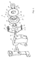
- the roller axis 13 sits Thread roller 11 rotatably in a bearing block 15.
- This bearing block 15 is on the Ship embroidery machine attachable.
- a bevel gear 17 is located on the roller axis 13 arranged.
- the bevel gear 17 is in engagement with a bevel gear 18 Thread roller shaft 16 (Fig. 4) of a Schifflistickmaschine.
- a thread guide shell 21 is on the roller block side of the bearing block 15 arranged. This is with a thread guide eyelet 20 and thread guide slots 22,24 equipped, in which the running on the thread roll 11 and that of the thread roll 11 is guided thread away.
- On the through the Thread guide shell 21 passing through roller axis 13 are first as Coupling serving locking disc 23, then a rotatable relative to this Base part 25 of the thread roller 11 and a spring piece 29 attached.
- On the Base part 25 is a flange 27 to complete thread roller 11 clipped.
- the locking disk 23 and the spring piece 29 sit non-rotatably on the roller axis 13.
- a bearing sleeve 31 is formed on which the thread roller 11 is stored.
- the base part 25 is mounted on the bearing sleeve 31 by means of the hub 33.
- a cylindrical thread winding surface 35 on the base part 25 educated. This can be covered with a suitable, non-slip material.
- Roll flange 37 formed, which projects beyond the thread winding surface 35 and thereby limited to one side. The other side of the winding area is covered by the clipped on flange 27 limited.
- This has three resilient latches 39, which through snap openings 41 in the wall facing the locking disk 23 43 of the base part 25 pushed into the edge of these three snap-in openings 41 engage.
- teeth 45 are perpendicular to Wall 43 formed flanks and are on the back with a flat Incline shaped.
- the teeth 45 are corresponding to the locking disk 23 Wells 47 formed.
- the roller axis 13, the Locking disc 23 and the thread roller 11 together in the direction of arrow 48. Die interacting vertical flanks of teeth 45 and depressions 47 cause the thread roll roller 11 not to rotate more rapidly in the direction of arrow 48 can be considered as the locking disc 23 thread therefore leads to a rotation of the Thread roller 11 in the direction of the arrow. If the thread roller shaft 16 is braked and the Thread roller 11 can not be rotated by a thread Tension built up in the thread.
- the resilient element 49 consists of two resilient arms 51 on one of the Ring axis to be fastened ring part 29.
- the resilient arms 51 are each divided into two and each have a pressure head 53 at the two ends.
- the four Pressure heads 53 are there to press against the wall 43 and thereby to press the base part 25 against the locking disk 23. The higher the spring force, the more higher is the thread tension required for the backward rotation of the thread roller roll 11.
- Analog to this slip clutch between the thread roller 11 and the Roller axis 13 can alternatively one between the roller axis 13 and the Bevel gear 17 be formed.
- the version shown is prefers.
- the order of locking disc 23, Thread roller 11 and spring piece 29 may be reversed on the roller axis 13.
- the embodiment shown has the advantage that the first on the roller axis 13th part to be placed is arranged on the inside of the roller axis 13 and that in each case The following also follows the previous one radially.
- a spring piece 29, whose spring force has decreased, can be replaced very easily.
- the slip clutch can also be designed such that a manual Forward rotation of the thread roller 11 is possible. Nevertheless, the Slip clutch can transmit a braking force necessary for embroidery. Therefore the force to be used for manual turning of the thread reel must be greater than this braking force, or is the slip clutch, e.g. by axial displacement the thread roller 11 on the roller axis 13, can be decoupled.
- the thread roller 11 can also be constructed differently, e.g. from three pieces or with the Thread winding surface 35 on flange 27.
Landscapes
- Engineering & Computer Science (AREA)
- Textile Engineering (AREA)
- Sewing Machines And Sewing (AREA)
- Yarns And Mechanical Finishing Of Yarns Or Ropes (AREA)
- Knitting Machines (AREA)
Abstract
Description
- Figur 1:
- eine Explosionszeichnung der Teile einer Fadenwalzenrolle und ihrer Verbindungsteile zur Fadenwalze,
- Figur 2:
- eine zweite Explosionszeichung derselben Teile aus einer anderen Richtung gesehen,
- Figur 3:
- ein Vertikalschnitt durch eine Anordnung einer Fadenwalzenrolle,
- Figur 4:
- einen Horizontalschnitt durch dieselbe Anordnung.
Claims (11)
- Stickmaschine mit einer Vielzahl von jeweils einer Stickstelle zugeordneten und miteinander in Wirkverbindung stehenden Fadenwalzenrollen (11), dadurch gekennzeichnet, dass die Wirkverbindung derart ausgebildet ist, dass ein aufgrund der Wirkverbindung auf die Wickelfläche (35) der Fadenwalzenrolle (11) wirkendes, vorwärts drehendes Moment derart begrenzt ist, dass ein maximaler, auf einen in falscher Wickelrichtung auf die Wickelfläche (35) aufgewickelten Faden ausgeübter Zug geringer ist als ein für einen Nadelbruch erforderlicher minimaler Zug.
- Stickmaschine nach Anspruch 1, bei der die Wirkverbindung der Fadenwalzenrollen über eine gemeinsame Fadenwalzenwelle (16) erreicht ist, mit der jede Fadenwalzenrolle in Verbindung steht, dadurch gekennzeichnet, dass die an der Fadenwalzenrolle (11) ausgebildete Wickelfläche (35) und mit ihr mechanisch zwingend wirkverbundene Teile (25) durch den Zug des Fadens relativ zu den mit der Fadenwalzenwelle (16) in mechanisch zwingender Wirkverbindung stehenden Teilen (23,23,17) verdrehbar ist.
- Stickmaschine nach einem der Ansprüche 1 oder 2, gekennzeichnet durch eine in einer Drehrichtung wirkende, den maximalen Zug begrenzende Rutschkupplung (23,47,25,45,29).
- Stickmaschine nach Anspruch 3, dadurch gekennzeichnet, dass die Rutschkupplung (23,47,25,45,29) zwischen der Fadenwalzenrolle (11) und einer Rollenachse (13) oder einem mit der Rollenachse (13) in zwingender Wirkverbindung stehenden Teil (23) angeordnet ist.
- Stickmaschine nach einem der Ansprüche 1 bis 4, gekennzeichnet durch eine Fadenwalzenrolle (11) nach Anspruch 6.
- Fadenwalzenrolle (11) für eine Stickmaschine, mit einer Rollenachse (13), gekennzeichnet durch eine Rutschkupplung (23,47,25,45,29) zwischen einem auf der Rollenachse (13) angeordnetem Kupplungsteil (23) und einem gegenüber diesem Kupplungsteil (23) verdrehbaren, mit einer Fadenwickelfläche (35) verbundenen Grundteil (25) der Fadenwalzenrolle (11).
- Fadenwalzenrolle nach Anspruch 6, dadurch gekennzeichnet, dass das Kupplungsteil (23) und das gegenüber diesem verdrehbare Grundteil (25) der Fadenwalzenrolle (11) zusammenwirkende Kupplungsflächen (45,47) aufweisen, welche die Achsrichtung der Rollenachse (13) schneidend ausgerichtet sind.
- Fadenwalzenrolle nach Anspruch 6 oder 7, dadurch gekennzeichnet, dass die Rutschkupplung (23,47,25,45,29) zwei aneinander anliegende, einander entsprechend gezahnte und in lediglich einer Richtung gegeneinander verschiebbare Flächen (45,47) und diese Flächen gegeneinander pressende Federmittel (49) aufweist.
- Fadenwalzenrolle nach Anspruch 8, dadurch gekennzeichnet, dass die Federmittel (49) an einem auf die Rollenachse (13) aufgesetzten Teil (29) ausgebildet sind, welches mit der Rollenachse (13) mitdreht.
- Fadenwalzenrolle nach einem der Ansprüche 6 bis 9, dadurch gekennzeichnet, dass das gegenüber dem Kupplungsstück (23) verdrehbare Grundteil (25) mit einer Nabe (33) auf einer am Kupplungsteil (23) ausgebildeten Lagerhülse (31) gelagert ist.
- Fadenwalzenrolle nach einem der Ansprüche 6 bis 10, mit einer optisch oder elektronisch ablesbaren Markierung, anhand welcher ein Drehen oder Stehen der Fadenwalzenrolle erfassbar ist.
Applications Claiming Priority (2)
| Application Number | Priority Date | Filing Date | Title |
|---|---|---|---|
| CH24172000 | 2000-12-12 | ||
| CH24172000 | 2000-12-12 |
Publications (2)
| Publication Number | Publication Date |
|---|---|
| EP1215326A1 true EP1215326A1 (de) | 2002-06-19 |
| EP1215326B1 EP1215326B1 (de) | 2004-01-21 |
Family
ID=4569126
Family Applications (1)
| Application Number | Title | Priority Date | Filing Date |
|---|---|---|---|
| EP01811112A Expired - Lifetime EP1215326B1 (de) | 2000-12-12 | 2001-11-20 | Fadenwalzenrolle |
Country Status (5)
| Country | Link |
|---|---|
| EP (1) | EP1215326B1 (de) |
| KR (1) | KR100749869B1 (de) |
| AT (1) | ATE258245T1 (de) |
| DE (1) | DE50101353D1 (de) |
| TR (1) | TR200400547T4 (de) |
Citations (3)
| Publication number | Priority date | Publication date | Assignee | Title |
|---|---|---|---|---|
| US3356050A (en) * | 1964-12-30 | 1967-12-05 | Urscheler Jack Anton | Tension devicess for embroidery machines |
| GB1133730A (en) * | 1965-02-04 | 1968-11-13 | Bemberg Ag | Improvements relating to the unwinding and winding of yarn bands and webs of material |
| EP0795638A1 (de) * | 1996-03-15 | 1997-09-17 | Franz Lässer AG | Verfahren zur Stichbildung bei einer Schifflistickmaschine und Vorrichtung zur Durchführung des Verfahrens |
Family Cites Families (5)
| Publication number | Priority date | Publication date | Assignee | Title |
|---|---|---|---|---|
| KR930011391B1 (ko) * | 1990-12-20 | 1993-12-04 | 동양정밀공업 주식회사 | 생활정보수신 단말장치의 정보 처리회로 |
| KR960000216B1 (ko) * | 1993-06-25 | 1996-01-03 | 삼성전자주식회사 | 메모리 카드 |
| KR100216600B1 (ko) * | 1996-12-21 | 1999-08-16 | 정선종 | 영상 신호 벡터 양자화기를 위한 다중 부호어 전송 방법 |
| EP2406703B1 (de) * | 2009-03-12 | 2018-11-28 | Immersion Corporation | System und verfahren für friktionsdisplays und zusätzliche haptische effekte |
| KR101213169B1 (ko) * | 2011-06-30 | 2012-12-18 | 와이즈플래닛(주) | 에어리어 카메라를 이용한 비쥬얼 엔코더 시스템 |
-
2001
- 2001-11-20 EP EP01811112A patent/EP1215326B1/de not_active Expired - Lifetime
- 2001-11-20 DE DE50101353T patent/DE50101353D1/de not_active Expired - Lifetime
- 2001-11-20 AT AT01811112T patent/ATE258245T1/de active
- 2001-11-20 TR TR2004/00547T patent/TR200400547T4/xx unknown
- 2001-12-10 KR KR1020010077756A patent/KR100749869B1/ko not_active Expired - Fee Related
Patent Citations (3)
| Publication number | Priority date | Publication date | Assignee | Title |
|---|---|---|---|---|
| US3356050A (en) * | 1964-12-30 | 1967-12-05 | Urscheler Jack Anton | Tension devicess for embroidery machines |
| GB1133730A (en) * | 1965-02-04 | 1968-11-13 | Bemberg Ag | Improvements relating to the unwinding and winding of yarn bands and webs of material |
| EP0795638A1 (de) * | 1996-03-15 | 1997-09-17 | Franz Lässer AG | Verfahren zur Stichbildung bei einer Schifflistickmaschine und Vorrichtung zur Durchführung des Verfahrens |
Also Published As
| Publication number | Publication date |
|---|---|
| EP1215326B1 (de) | 2004-01-21 |
| KR100749869B1 (ko) | 2007-08-21 |
| KR20020048285A (ko) | 2002-06-22 |
| ATE258245T1 (de) | 2004-02-15 |
| DE50101353D1 (de) | 2004-02-26 |
| TR200400547T4 (tr) | 2004-07-21 |
Similar Documents
| Publication | Publication Date | Title |
|---|---|---|
| DE2220792C3 (de) | Einstellbarer Tiefenanschlag für ein tragbares kraftangetriebenes Werkzeug | |
| DE3907753C1 (de) | ||
| DE4337874A1 (de) | Laufübungs-Gerät mit spannungsbegrenzter Laufband-Einstellung | |
| EP0109666B1 (de) | Handgerät mit verstellbarem Tiefenanschlag | |
| EP1222131B1 (de) | Handgerät zum übertragen eines filmes von einem trägerband auf ein substrat, mit einer rücklaufsperre | |
| DE19720795A1 (de) | Fadenbremse und damit ausgerüstete Textilmaschine und Fadenliefervorrichtung | |
| DE69923525T2 (de) | Rotierendes Schneidewerkzeug für Mäher | |
| DE19920400C1 (de) | Nähmaschine mit einer Überlastkupplung | |
| EP2050853B1 (de) | Nähmaschine und Greifer-System für Nähmaschine | |
| CH636578A5 (de) | Fadenbremse. | |
| DE3916009A1 (de) | Schneidkopf fuer ein pflanzenschneidgeraet | |
| EP1215326B1 (de) | Fadenwalzenrolle | |
| DE1785157B1 (de) | Vorrichtung zum Durchschneiden eines laufenden Textilgarnes | |
| DE2830511C2 (de) | Schlagbohrmaschine mit Zweiganggetriebe und einer Einrichtung zum Umschalten der Getriebegänge und zum Umstellen von Bohren auf Schlagbohren | |
| DE2936581A1 (de) | Vorrichtung zur ueberwachung der fadenzufuhr bei textilmaschinen | |
| CH617638A5 (de) | ||
| EP2050852B1 (de) | Nähmaschine und Greifer-System für Nähmaschine | |
| EP0476407B1 (de) | Vorrichtung zur Führung eines Wanderdeckels einer Karde oder Krempel | |
| DE2701718C2 (de) | Fadenspeicher- und -liefervorrichtung | |
| DE3414729A1 (de) | Fadenleitrolle | |
| EP1303659A1 (de) | Zungennadel mit abgesetztem zungenschaft | |
| DE4109782A1 (de) | Sitzgurteinzieheinrichtung | |
| EP0894760B1 (de) | Fadenliefervorrichtung und dafür geeignetes Antriebsrad | |
| DE1785157C (de) | Vorrichtung zum Durchschneiden eines laufenden Texülgames | |
| CH626961A5 (en) | Coupling with overload safeguard |
Legal Events
| Date | Code | Title | Description |
|---|---|---|---|
| PUAI | Public reference made under article 153(3) epc to a published international application that has entered the european phase |
Free format text: ORIGINAL CODE: 0009012 |
|
| AK | Designated contracting states |
Kind code of ref document: A1 Designated state(s): AT BE CH CY DE DK ES FI FR GB GR IE IT LI LU MC NL PT SE TR |
|
| AX | Request for extension of the european patent |
Free format text: AL;LT;LV;MK;RO;SI |
|
| 17P | Request for examination filed |
Effective date: 20020606 |
|
| 17Q | First examination report despatched |
Effective date: 20020925 |
|
| AKX | Designation fees paid |
Designated state(s): AT BE CH CY DE DK ES FI FR GB GR IE IT LI LU MC NL PT SE TR |
|
| GRAP | Despatch of communication of intention to grant a patent |
Free format text: ORIGINAL CODE: EPIDOSNIGR1 |
|
| GRAS | Grant fee paid |
Free format text: ORIGINAL CODE: EPIDOSNIGR3 |
|
| GRAA | (expected) grant |
Free format text: ORIGINAL CODE: 0009210 |
|
| AK | Designated contracting states |
Kind code of ref document: B1 Designated state(s): AT BE CH CY DE DK ES FI FR GB GR IE IT LI LU MC NL PT SE TR |
|
| PG25 | Lapsed in a contracting state [announced via postgrant information from national office to epo] |
Ref country code: NL Free format text: LAPSE BECAUSE OF FAILURE TO SUBMIT A TRANSLATION OF THE DESCRIPTION OR TO PAY THE FEE WITHIN THE PRESCRIBED TIME-LIMIT Effective date: 20040121 Ref country code: IE Free format text: LAPSE BECAUSE OF FAILURE TO SUBMIT A TRANSLATION OF THE DESCRIPTION OR TO PAY THE FEE WITHIN THE PRESCRIBED TIME-LIMIT Effective date: 20040121 Ref country code: GB Free format text: LAPSE BECAUSE OF FAILURE TO SUBMIT A TRANSLATION OF THE DESCRIPTION OR TO PAY THE FEE WITHIN THE PRESCRIBED TIME-LIMIT Effective date: 20040121 Ref country code: CY Free format text: LAPSE BECAUSE OF FAILURE TO SUBMIT A TRANSLATION OF THE DESCRIPTION OR TO PAY THE FEE WITHIN THE PRESCRIBED TIME-LIMIT Effective date: 20040121 Ref country code: FI Free format text: LAPSE BECAUSE OF FAILURE TO SUBMIT A TRANSLATION OF THE DESCRIPTION OR TO PAY THE FEE WITHIN THE PRESCRIBED TIME-LIMIT Effective date: 20040121 |
|
| REG | Reference to a national code |
Ref country code: GB Ref legal event code: FG4D Free format text: NOT ENGLISH |
|
| REG | Reference to a national code |
Ref country code: CH Ref legal event code: EP |
|
| REG | Reference to a national code |
Ref country code: IE Ref legal event code: FG4D Free format text: GERMAN |
|
| REF | Corresponds to: |
Ref document number: 50101353 Country of ref document: DE Date of ref document: 20040226 Kind code of ref document: P |
|
| REG | Reference to a national code |
Ref country code: CH Ref legal event code: NV Representative=s name: RIEDERER HASLER & PARTNER PATENTANWAELTE AG |
|
| PG25 | Lapsed in a contracting state [announced via postgrant information from national office to epo] |
Ref country code: SE Free format text: LAPSE BECAUSE OF FAILURE TO SUBMIT A TRANSLATION OF THE DESCRIPTION OR TO PAY THE FEE WITHIN THE PRESCRIBED TIME-LIMIT Effective date: 20040421 Ref country code: DK Free format text: LAPSE BECAUSE OF FAILURE TO SUBMIT A TRANSLATION OF THE DESCRIPTION OR TO PAY THE FEE WITHIN THE PRESCRIBED TIME-LIMIT Effective date: 20040421 Ref country code: GR Free format text: LAPSE BECAUSE OF FAILURE TO SUBMIT A TRANSLATION OF THE DESCRIPTION OR TO PAY THE FEE WITHIN THE PRESCRIBED TIME-LIMIT Effective date: 20040421 |
|
| PG25 | Lapsed in a contracting state [announced via postgrant information from national office to epo] |
Ref country code: ES Free format text: LAPSE BECAUSE OF FAILURE TO SUBMIT A TRANSLATION OF THE DESCRIPTION OR TO PAY THE FEE WITHIN THE PRESCRIBED TIME-LIMIT Effective date: 20040502 |
|
| NLV1 | Nl: lapsed or annulled due to failure to fulfill the requirements of art. 29p and 29m of the patents act | ||
| GBV | Gb: ep patent (uk) treated as always having been void in accordance with gb section 77(7)/1977 [no translation filed] |
Effective date: 20040121 |
|
| REG | Reference to a national code |
Ref country code: IE Ref legal event code: FD4D |
|
| ET | Fr: translation filed | ||
| PG25 | Lapsed in a contracting state [announced via postgrant information from national office to epo] |
Ref country code: LU Free format text: LAPSE BECAUSE OF NON-PAYMENT OF DUE FEES Effective date: 20041120 |
|
| PLBE | No opposition filed within time limit |
Free format text: ORIGINAL CODE: 0009261 |
|
| STAA | Information on the status of an ep patent application or granted ep patent |
Free format text: STATUS: NO OPPOSITION FILED WITHIN TIME LIMIT |
|
| PG25 | Lapsed in a contracting state [announced via postgrant information from national office to epo] |
Ref country code: MC Free format text: LAPSE BECAUSE OF NON-PAYMENT OF DUE FEES Effective date: 20041130 Ref country code: BE Free format text: LAPSE BECAUSE OF NON-PAYMENT OF DUE FEES Effective date: 20041130 |
|
| 26N | No opposition filed |
Effective date: 20041022 |
|
| BERE | Be: lapsed |
Owner name: FRANZ *LASSER A.G. Effective date: 20041130 |
|
| PGFP | Annual fee paid to national office [announced via postgrant information from national office to epo] |
Ref country code: TR Payment date: 20061107 Year of fee payment: 6 |
|
| PGFP | Annual fee paid to national office [announced via postgrant information from national office to epo] |
Ref country code: FR Payment date: 20061124 Year of fee payment: 6 |
|
| PGFP | Annual fee paid to national office [announced via postgrant information from national office to epo] |
Ref country code: IT Payment date: 20061130 Year of fee payment: 6 |
|
| BERE | Be: lapsed |
Owner name: FRANZ *LASSER A.G. Effective date: 20041130 |
|
| PG25 | Lapsed in a contracting state [announced via postgrant information from national office to epo] |
Ref country code: PT Free format text: LAPSE BECAUSE OF NON-PAYMENT OF DUE FEES Effective date: 20040621 |
|
| REG | Reference to a national code |
Ref country code: FR Ref legal event code: ST Effective date: 20080930 |
|
| PG25 | Lapsed in a contracting state [announced via postgrant information from national office to epo] |
Ref country code: FR Free format text: LAPSE BECAUSE OF NON-PAYMENT OF DUE FEES Effective date: 20071130 |
|
| PG25 | Lapsed in a contracting state [announced via postgrant information from national office to epo] |
Ref country code: IT Free format text: LAPSE BECAUSE OF NON-PAYMENT OF DUE FEES Effective date: 20071120 |
|
| PG25 | Lapsed in a contracting state [announced via postgrant information from national office to epo] |
Ref country code: TR Free format text: LAPSE BECAUSE OF FAILURE TO SUBMIT A TRANSLATION OF THE DESCRIPTION OR TO PAY THE FEE WITHIN THE PRESCRIBED TIME-LIMIT Effective date: 20040121 |
|
| PGFP | Annual fee paid to national office [announced via postgrant information from national office to epo] |
Ref country code: DE Payment date: 20121121 Year of fee payment: 12 Ref country code: CH Payment date: 20121129 Year of fee payment: 12 |
|
| PGFP | Annual fee paid to national office [announced via postgrant information from national office to epo] |
Ref country code: AT Payment date: 20121113 Year of fee payment: 12 |
|
| REG | Reference to a national code |
Ref country code: CH Ref legal event code: PL |
|
| REG | Reference to a national code |
Ref country code: AT Ref legal event code: MM01 Ref document number: 258245 Country of ref document: AT Kind code of ref document: T Effective date: 20131120 |
|
| PG25 | Lapsed in a contracting state [announced via postgrant information from national office to epo] |
Ref country code: CH Free format text: LAPSE BECAUSE OF NON-PAYMENT OF DUE FEES Effective date: 20131130 Ref country code: LI Free format text: LAPSE BECAUSE OF NON-PAYMENT OF DUE FEES Effective date: 20131130 |
|
| REG | Reference to a national code |
Ref country code: DE Ref legal event code: R119 Ref document number: 50101353 Country of ref document: DE Effective date: 20140603 |
|
| PG25 | Lapsed in a contracting state [announced via postgrant information from national office to epo] |
Ref country code: DE Free format text: LAPSE BECAUSE OF NON-PAYMENT OF DUE FEES Effective date: 20140603 Ref country code: AT Free format text: LAPSE BECAUSE OF NON-PAYMENT OF DUE FEES Effective date: 20131120 |