EP1214514B1 - Fluideinleitung für ein heisses fluid in einer hohlraumstruktur - Google Patents
Fluideinleitung für ein heisses fluid in einer hohlraumstruktur Download PDFInfo
- Publication number
- EP1214514B1 EP1214514B1 EP00964199A EP00964199A EP1214514B1 EP 1214514 B1 EP1214514 B1 EP 1214514B1 EP 00964199 A EP00964199 A EP 00964199A EP 00964199 A EP00964199 A EP 00964199A EP 1214514 B1 EP1214514 B1 EP 1214514B1
- Authority
- EP
- European Patent Office
- Prior art keywords
- fluid
- insert
- inlet
- flow
- hollow structure
- Prior art date
- Legal status (The legal status is an assumption and is not a legal conclusion. Google has not performed a legal analysis and makes no representation as to the accuracy of the status listed.)
- Expired - Lifetime
Links
- 239000012530 fluid Substances 0.000 title claims abstract description 84
- 238000002485 combustion reaction Methods 0.000 claims abstract description 9
- 238000001816 cooling Methods 0.000 abstract description 8
- 230000008646 thermal stress Effects 0.000 abstract description 4
- 238000011084 recovery Methods 0.000 abstract 1
- 239000007789 gas Substances 0.000 description 25
- 230000000694 effects Effects 0.000 description 6
- 238000002844 melting Methods 0.000 description 5
- 239000004033 plastic Substances 0.000 description 5
- 229920003023 plastic Polymers 0.000 description 5
- 239000000463 material Substances 0.000 description 4
- 230000008018 melting Effects 0.000 description 4
- 238000010438 heat treatment Methods 0.000 description 3
- 238000004519 manufacturing process Methods 0.000 description 3
- 239000000203 mixture Substances 0.000 description 3
- 238000010276 construction Methods 0.000 description 2
- 238000009413 insulation Methods 0.000 description 2
- 238000004380 ashing Methods 0.000 description 1
- 239000003344 environmental pollutant Substances 0.000 description 1
- 235000021050 feed intake Nutrition 0.000 description 1
- 239000010408 film Substances 0.000 description 1
- 239000003779 heat-resistant material Substances 0.000 description 1
- 230000000977 initiatory effect Effects 0.000 description 1
- 238000009434 installation Methods 0.000 description 1
- 239000012212 insulator Substances 0.000 description 1
- 238000011031 large-scale manufacturing process Methods 0.000 description 1
- 239000002184 metal Substances 0.000 description 1
- 231100000719 pollutant Toxicity 0.000 description 1
- 238000004080 punching Methods 0.000 description 1
- 238000004064 recycling Methods 0.000 description 1
- 239000007787 solid Substances 0.000 description 1
- 239000010409 thin film Substances 0.000 description 1
Images
Classifications
-
- F—MECHANICAL ENGINEERING; LIGHTING; HEATING; WEAPONS; BLASTING
- F28—HEAT EXCHANGE IN GENERAL
- F28F—DETAILS OF HEAT-EXCHANGE AND HEAT-TRANSFER APPARATUS, OF GENERAL APPLICATION
- F28F9/00—Casings; Header boxes; Auxiliary supports for elements; Auxiliary members within casings
- F28F9/02—Header boxes; End plates
- F28F9/026—Header boxes; End plates with static flow control means, e.g. with means for uniformly distributing heat exchange media into conduits
- F28F9/027—Header boxes; End plates with static flow control means, e.g. with means for uniformly distributing heat exchange media into conduits in the form of distribution pipes
- F28F9/0273—Header boxes; End plates with static flow control means, e.g. with means for uniformly distributing heat exchange media into conduits in the form of distribution pipes with multiple holes
-
- F—MECHANICAL ENGINEERING; LIGHTING; HEATING; WEAPONS; BLASTING
- F02—COMBUSTION ENGINES; HOT-GAS OR COMBUSTION-PRODUCT ENGINE PLANTS
- F02M—SUPPLYING COMBUSTION ENGINES IN GENERAL WITH COMBUSTIBLE MIXTURES OR CONSTITUENTS THEREOF
- F02M26/00—Engine-pertinent apparatus for adding exhaust gases to combustion-air, main fuel or fuel-air mixture, e.g. by exhaust gas recirculation [EGR] systems
- F02M26/13—Arrangement or layout of EGR passages, e.g. in relation to specific engine parts or for incorporation of accessories
- F02M26/17—Arrangement or layout of EGR passages, e.g. in relation to specific engine parts or for incorporation of accessories in relation to the intake system
- F02M26/18—Thermal insulation or heat protection
-
- F—MECHANICAL ENGINEERING; LIGHTING; HEATING; WEAPONS; BLASTING
- F02—COMBUSTION ENGINES; HOT-GAS OR COMBUSTION-PRODUCT ENGINE PLANTS
- F02M—SUPPLYING COMBUSTION ENGINES IN GENERAL WITH COMBUSTIBLE MIXTURES OR CONSTITUENTS THEREOF
- F02M35/00—Combustion-air cleaners, air intakes, intake silencers, or induction systems specially adapted for, or arranged on, internal-combustion engines
- F02M35/10—Air intakes; Induction systems
- F02M35/10091—Air intakes; Induction systems characterised by details of intake ducts: shapes; connections; arrangements
- F02M35/10118—Air intakes; Induction systems characterised by details of intake ducts: shapes; connections; arrangements with variable cross-sections of intake ducts along their length; Venturis; Diffusers
-
- F—MECHANICAL ENGINEERING; LIGHTING; HEATING; WEAPONS; BLASTING
- F02—COMBUSTION ENGINES; HOT-GAS OR COMBUSTION-PRODUCT ENGINE PLANTS
- F02M—SUPPLYING COMBUSTION ENGINES IN GENERAL WITH COMBUSTIBLE MIXTURES OR CONSTITUENTS THEREOF
- F02M35/00—Combustion-air cleaners, air intakes, intake silencers, or induction systems specially adapted for, or arranged on, internal-combustion engines
- F02M35/10—Air intakes; Induction systems
- F02M35/10209—Fluid connections to the air intake system; their arrangement of pipes, valves or the like
- F02M35/10222—Exhaust gas recirculation [EGR]; Positive crankcase ventilation [PCV]; Additional air admission, lubricant or fuel vapour admission
-
- F—MECHANICAL ENGINEERING; LIGHTING; HEATING; WEAPONS; BLASTING
- F02—COMBUSTION ENGINES; HOT-GAS OR COMBUSTION-PRODUCT ENGINE PLANTS
- F02M—SUPPLYING COMBUSTION ENGINES IN GENERAL WITH COMBUSTIBLE MIXTURES OR CONSTITUENTS THEREOF
- F02M35/00—Combustion-air cleaners, air intakes, intake silencers, or induction systems specially adapted for, or arranged on, internal-combustion engines
- F02M35/10—Air intakes; Induction systems
- F02M35/10242—Devices or means connected to or integrated into air intakes; Air intakes combined with other engine or vehicle parts
- F02M35/10262—Flow guides, obstructions, deflectors or the like
-
- F—MECHANICAL ENGINEERING; LIGHTING; HEATING; WEAPONS; BLASTING
- F02—COMBUSTION ENGINES; HOT-GAS OR COMBUSTION-PRODUCT ENGINE PLANTS
- F02M—SUPPLYING COMBUSTION ENGINES IN GENERAL WITH COMBUSTIBLE MIXTURES OR CONSTITUENTS THEREOF
- F02M35/00—Combustion-air cleaners, air intakes, intake silencers, or induction systems specially adapted for, or arranged on, internal-combustion engines
- F02M35/10—Air intakes; Induction systems
- F02M35/10242—Devices or means connected to or integrated into air intakes; Air intakes combined with other engine or vehicle parts
- F02M35/10268—Heating, cooling or thermal insulating means
-
- F—MECHANICAL ENGINEERING; LIGHTING; HEATING; WEAPONS; BLASTING
- F02—COMBUSTION ENGINES; HOT-GAS OR COMBUSTION-PRODUCT ENGINE PLANTS
- F02M—SUPPLYING COMBUSTION ENGINES IN GENERAL WITH COMBUSTIBLE MIXTURES OR CONSTITUENTS THEREOF
- F02M26/00—Engine-pertinent apparatus for adding exhaust gases to combustion-air, main fuel or fuel-air mixture, e.g. by exhaust gas recirculation [EGR] systems
- F02M26/13—Arrangement or layout of EGR passages, e.g. in relation to specific engine parts or for incorporation of accessories
- F02M26/17—Arrangement or layout of EGR passages, e.g. in relation to specific engine parts or for incorporation of accessories in relation to the intake system
- F02M26/19—Means for improving the mixing of air and recirculated exhaust gases, e.g. venturis or multiple openings to the intake system
-
- Y—GENERAL TAGGING OF NEW TECHNOLOGICAL DEVELOPMENTS; GENERAL TAGGING OF CROSS-SECTIONAL TECHNOLOGIES SPANNING OVER SEVERAL SECTIONS OF THE IPC; TECHNICAL SUBJECTS COVERED BY FORMER USPC CROSS-REFERENCE ART COLLECTIONS [XRACs] AND DIGESTS
- Y02—TECHNOLOGIES OR APPLICATIONS FOR MITIGATION OR ADAPTATION AGAINST CLIMATE CHANGE
- Y02T—CLIMATE CHANGE MITIGATION TECHNOLOGIES RELATED TO TRANSPORTATION
- Y02T10/00—Road transport of goods or passengers
- Y02T10/10—Internal combustion engine [ICE] based vehicles
- Y02T10/12—Improving ICE efficiencies
Definitions
- the invention relates to a fluid introduction, in particular as exhaust gas recirculation can be used in the intake tract of an internal combustion engine, according to the preamble of claim 1.
- the exhaust gas inlet double-walled perform.
- the exhaust gas is introduced through the inner tube into the intake tract, wherein the cavity resulting between the double wall is insulating opposite the contact point of the exhaust gas inlet with the suction pipe acts.
- a space is created through the gap Part of the sucked fresh air passed, which removed before a throttle is and passes through a bypass line in the interspace.
- the cooling air passes through corresponding openings parallel to the exhaust gas flow back to the intake system.
- a thermally loadable gas guide element 26 (see FIG. 2) be provided, which the wall of the intake before a direct Impact of the hot exhaust gas flow protects.
- the hot exhaust flow has enough time to deal with the intake air to mix.
- the gas guide element is made of heat-resistant Material made. This material has a high thermal stability and therefore can buffer heat spikes in the introduced exhaust gas or conduct and in operating conditions less heat leave again.
- this component means an increase in the weight of the assembly. This is especially in mobile use, such. As in motor vehicles, not desired.
- the gas routing element increases the material and manufacturing costs for the intake tract.
- the object of the invention is therefore to provide a fluid inlet for initiating a to create hot fluids in a cooler which are inexpensive to manufacture is, has the lowest possible component weight, and the assembly effectively protects against thermal stress from the fluid introduced. This object is solved by the features of claim 1.
- the fluid introduction according to the invention consists of three structural functional areas, the cavity structure, the inlet nozzle and an insert.
- the Cavity structure is suitable for the passage of a fluid and z. B. off consist of an intake manifold for an internal combustion engine.
- the inlet pipe is suitable for connection to a supply line, wherein through the supply line the hot fluid to be introduced is guided. These components are interconnected connected.
- the advantage of the invention can be used in various ways. Of the Insert needed compared to the inserts used in the prior art a smaller wall thickness, whereby weight can be saved.
- the lower heat capacity of the insert is due to the lower thermal Burden made up.
- Another possibility is choosing one lower melting material for use. Here you can even high-melting plastics should be considered. This reduces the component weight and allows a more economical production of the insert.
- a plastic part can also be z. B. easier to dispose of by ashing.
- a third possibility of using the described advantage lies in one Increase the temperature of the fluid to be introduced.
- a suitable application if the Fluid inlet for exhaust gas recirculation in the intake of an internal combustion engine is being used. This is especially in modern diesel engines a high exhaust gas recirculation rate in certain operating conditions required in be able to comply with the required exhaust emissions. These high exhaust gas recirculation rates can be realized with economically manufactured parts, if that The design principle described is followed.
- the cavity can as Bypass line section be designed for the passed fluid. This one passed through flow then does not mix with the introduced fluid, so that they have additional cooling properties over the heating Use has. In this way, the thermal load of the insert be further reduced.
- the walls of the insert are provided with openings, the described gap connect to the inside of the insert.
- the Fuidströmung along the insides the insert causes at the openings a suction jet pump effect, the already mentioned cool, fürzu yogade fluid from the gap sucks.
- On the inner sides flows through the fluid to be passed, which is just mixed with the fluid introduced and thereby heated becomes.
- the fluid sucked through the apertures initially forms a film on the inside of the insert, creating a cooling shield the warmer displaced from the inside attacking fluid flow. In this way the thermal load of the insert can be further reduced, whereby the described advantages of the invention can be used more efficiently.
- the described flow effects can be used very efficiently, if the walls of the insert according to a particular embodiment the invention are annular closed. This creates one of the insides of the insert included mixing section, in which the Fluid enters together with the fluid to be passed. It is advantageous to provide the mixing section with a circular cross-section. By such regular cross-sectional shapes, the prevailing at the fluid inlet Flow conditions are most reliably affected.
- a further advantageous embodiment of the means for reducing the heat input consists in a double-walled construction principle of the inlet nozzle. This has an inner wall and an outer wall, with the in Interspace of these walls located fluid acts as an insulator. The to be initiated Fluid is passed through the cross section formed by the inner wall.
- An alternative solution for the introduction of fluid provides, the inlet in the End region, which extends into the interior of the cavity structure, with outlet openings to be provided, which in the direction of the flow direction of the passed Fluids wise.
- the fluid to be introduced is taking advantage of the Saugstrahlpumpen bines detected and entrained by the flow of the fluid passed through, whereby a rapid mixing takes place.
- the mixing effect at the same time a cooling of the fluid to be introduced and a heating of the fluid to be passed.
- the resulting temperature is however in the range of the permissible thermal stress on the inside of the insert.
- the outlet openings are along the flanks at the end of the inlet port arranged.
- the multiplicity of openings improves the mixing effect, because the fluid flow of the fluid to be introduced into many small partial flows is broken up.
- the outlet openings provided with baffle plates.
- these baffles can be easily by punching produce.
- the baffles are bent into the interior of the inlet nozzle and thus cause an optimal mixing of the réelleurgiden Fluids with the fluid to be passed.
- the baffles cause a Applying the fluid flow to be introduced at the exit to the end region of the Einleitstutzens, creating a direct wall contact of the fluid to be introduced is avoided with the walls of the cavity structure. This takes place first after a sufficient mixing distance in the further course of fürzu meetingden Flow in the cavity structure.
- the inlet connection with respect to the flow through the cavity structure provided with a flow-optimized outer contour.
- flowing around the inlet nozzle then results in a laminar flow along the outer contour of the inlet, in particular its end.
- the mixing result with the fluid to be introduced is improved.
- connection structure For a large-scale production, the connection structure according to a expedient training of the inventive concept as a bayonet lock manufactured. It creates a module that is easy in cavity structures can be incorporated. Especially if they are made of plastic leaves the corresponding receptacle as a counterpart of the bayonet lock easy to integrate into the wall structure. Inlet nozzle and connection structure can then be run as a standard component, resulting in high volumes achieve. This leads to an increased efficiency of the solution. Through the bayonet closure, the fluid introduction can be easily mounted, although the reduced installation costs to a further increase the economic efficiency of the fluid introduction contributes.
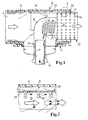
- a fluid inlet 10 according to FIG. 1 represents a section of an otherwise not shown intake tract for an internal combustion engine. This consists from a cavity structure 13, which is provided with an inlet 11 and an outlet 12 is provided to the air flow of the intake air, characterized by wide Arrows to be able to pass. Inlet and outlet can be used as interfaces of the considered system of fluid introduction.
- a bayonet lock 14 an inlet pipe 15 is fixed in the cavity structure. This has a terminal 16 which is connected to an exhaust gas supply line, not shown can be connected. The flow of exhaust gas is indicated by thin arrows characterized.
- the inlet pipe is double-walled, with the inner pipe 17 of the insulation is used, so that excessive heating of the cavity structure 13 is avoided over the bayonet lock.
- the double-walled Part of the Einleitstutzens joins a bend 18, which is the exhaust redirects in the direction of the intake air.
- Outlet openings 19 are provided, the baffles 20 and thus have a directed Allow introduction of the exhaust gas into the cavity structure.
- the curved one Area of the inlet is flat, so that this through the intake air can be flowed around easily while entraining the exhaust gas.
- the use is through Mounting ribs 24 held in the cavity structure 13. He has a lower one Outer diameter, as the inner diameter of the cavity structure. In this way, a gap 25 is formed by the intake air can be flowed through. This secondary air flow is indicated by dashed arrows.
Landscapes
- Engineering & Computer Science (AREA)
- Mechanical Engineering (AREA)
- General Engineering & Computer Science (AREA)
- Chemical & Material Sciences (AREA)
- Combustion & Propulsion (AREA)
- Physics & Mathematics (AREA)
- Thermal Sciences (AREA)
- Exhaust-Gas Circulating Devices (AREA)
- Blow-Moulding Or Thermoforming Of Plastics Or The Like (AREA)
- Nozzles (AREA)
- Temperature-Responsive Valves (AREA)
- Exhaust Gas After Treatment (AREA)
Description
- Figur 1
- den Längsschnitt durch eine Fluideinleitung und
- Figur 2
- das Detail X gemäß Figur 1 wobei verschiedene Fluidströme schematisch durch Pfeile dargestellt sind.
Claims (8)
- Fluideinteltung, insbesondere Abgasrückführung in den Ansaugtrakt einer Brennkraftmaschine, bestehend auswobei der Einleitstutzen eine höhere Temperaturbeständigkeit aufweist, als die Hohlraumstruktur und der Einleitstutzen gegenüber dem einzuleitenden Fluid temperaturbeständig ist und der Einsatz (23) die Wandungen der Hohlraumstruktur gegen das eingeleitete Fluid abschirmt,einer Hohlraumstruktur (13) zur Durchleitung eines Fluides von einem Einlaß (11) zu einem Auslaß (12),einem Einleitstutzen (15) zur Einleitung eines Fluides, welches wärmer als das durchgeleitete Fluid ist, in die Hohlraumstruktur undeinem Einsatz (23), welcher in der Hohlraumstruktur mit einer Innenseite (22) im Bereich des durch den Einleitstutzen eingeleiteten Fluides angebracht ist,
wobei die Wandungen des Einsatzes (23) zumindest im wesentlichen in der Strömungsrichtung des eingeleiteten Fluides ausgerichtet sind und zwischen dem Einsatz (23) und den Wandungen der Hohlraumstruktur (13) ein Zwischenraum (25) vorgesehen ist
dadurch gekennzeichnet, daß die Wandungen des Einsatzes mit Durchbrüchen (26) versehen sind, die die Innenseite (22) mit dem Zwischenraum (25) verbinden. - Fluideinleitung nach Anspruch 1, dadurch gekennzeichnet, daß die Wandungen des Einsatzes ringförmig geschlossen sind, so daß die Innenseiten (22) eine Mischstrecke (21) bilden.
- Fluideinleitung nach Anspruch 2, dadurch gekennzeichnet, daß die Mischstrecke (21) einen kreisförmigen Querschnitt aufweist.
- Fluideinleitung nach einem der vorherigen Ansprüche, dadurch gekennzeichnet, daß der Einleitstutzen (15) eine Krümmung (18) zur Umleitung des einzuleitenden Fluides in Richtung des durchgeleiteten Fluides aufweist.
- Fluideinleitung nach einem der vorherigen Ansprüche, dadurch gekennzeichnet, daß der Einleitstutzen (15) doppelwandig ausgeführt ist und das einzuleitende Fluid durch ein Innenrohr (17) des Einleitstutzens geführt ist.
- Fluideinleitung nach einem der vorherigen Ansprüche, dadurch gekennzeichnet, daß Austrittsöffnungen (19) mit Leitblechen (20) zur Beeinflussung der Strömungsrichtung des eingeleiteten Fluides am Einleitstutzen versehen sind.
- Fluideinleitung nach einem der vorherigen Ansprüche, dadurch gekennzeichnet, daß der Einleitstutzen (15) in dem Bereich der Fluideinleitung eine strömungsoptimierte Außenkontur hinsichtlich der durchgeleiteten Strömung aufweist.
- Fluideinleitung nach einem der vorherigen Ansprüche, dadurch gekennzeichnet, daß der Einleitstutzen (15) mit einem Bajonettverschluß (14) in der Hohlraumstruktur (13) befestigt ist.
Applications Claiming Priority (3)
| Application Number | Priority Date | Filing Date | Title |
|---|---|---|---|
| DE19945769A DE19945769A1 (de) | 1999-09-24 | 1999-09-24 | Fluideinleitung für ein heißes Fluid in einer Hohlraumstruktur |
| DE19945769 | 1999-09-24 | ||
| PCT/EP2000/009141 WO2001023738A1 (de) | 1999-09-24 | 2000-09-19 | Fluideinleitung für ein heisses fluid in einer hohlraumstruktur |
Publications (2)
| Publication Number | Publication Date |
|---|---|
| EP1214514A1 EP1214514A1 (de) | 2002-06-19 |
| EP1214514B1 true EP1214514B1 (de) | 2005-04-20 |
Family
ID=7923142
Family Applications (1)
| Application Number | Title | Priority Date | Filing Date |
|---|---|---|---|
| EP00964199A Expired - Lifetime EP1214514B1 (de) | 1999-09-24 | 2000-09-19 | Fluideinleitung für ein heisses fluid in einer hohlraumstruktur |
Country Status (6)
| Country | Link |
|---|---|
| US (1) | US6672292B2 (de) |
| EP (1) | EP1214514B1 (de) |
| JP (1) | JP4498653B2 (de) |
| AT (1) | ATE293750T1 (de) |
| DE (2) | DE19945769A1 (de) |
| WO (1) | WO2001023738A1 (de) |
Families Citing this family (41)
| Publication number | Priority date | Publication date | Assignee | Title |
|---|---|---|---|---|
| WO2001079680A1 (de) * | 2000-04-17 | 2001-10-25 | Robert Bosch Gmbh | Vorrichtung zur mischung und dosierung von gasströmen an verbrennungskraftmaschinen |
| DE10042247C5 (de) * | 2000-08-29 | 2006-09-14 | Robert Bosch Gmbh | Mischeinheit für Gasströme an einer Verbrennungskraftmaschine |
| SE522310C2 (sv) * | 2001-03-02 | 2004-02-03 | Volvo Lastvagnar Ab | Anordning och förfarande för tillförsel av återcirkulerade avgaser |
| DE10210971A1 (de) * | 2002-03-13 | 2003-09-25 | Daimler Chrysler Ag | Vorrichtung zur Abgasrückführung |
| US7213639B2 (en) * | 2005-03-16 | 2007-05-08 | Detroit Diesel Coporation | Heat exchanger exhaust gas recirculation cooler |
| FR2895028B1 (fr) * | 2005-12-20 | 2008-03-21 | Renault Sas | Dispositif de melange de fluides pour groupe motopropulseur |
| US20090071150A1 (en) * | 2006-01-27 | 2009-03-19 | Borgwarner Inc. | Mixing Unit for LP-EGR Condensate Into the Compressor |
| US7320301B1 (en) * | 2007-04-04 | 2008-01-22 | Gm Global Technology Operations, Inc. | Clock and anchor pipe fitting and method |
| JP4657250B2 (ja) * | 2007-05-29 | 2011-03-23 | 株式会社デンソー | 吸気装置 |
| FR2918416B1 (fr) * | 2007-07-02 | 2013-04-05 | Coutier Moulage Gen Ind | Dispositif de recirculation des gaz d'echappement pour moteur a combustion interne |
| DE102007061324A1 (de) * | 2007-12-19 | 2009-06-25 | Boa Balg- Und Kompensatoren-Technologie Gmbh | Vorrichtung zur Abgasrückführung |
| EP2245284A4 (de) * | 2008-01-24 | 2015-08-12 | Mack Trucks | Abgasrückführungsmischervorrichtung |
| FR2931900A1 (fr) * | 2008-05-29 | 2009-12-04 | Peugeot Citroen Automobiles Sa | Dispositif de repartition des gaz d'admission pour un moteur a combustion interne |
| FR2936284B1 (fr) * | 2008-09-25 | 2013-07-12 | Valeo Systemes Thermiques | Module de melange de deux gaz pour un echangeur de chaleur |
| FR2945582A1 (fr) * | 2009-05-18 | 2010-11-19 | Mann & Hummel Gmbh | Dispositif de recirculation des gaz d'echappement d'un moteur a combustion interne |
| DE202009009441U1 (de) | 2009-07-10 | 2009-10-01 | Boa Balg- Und Kompensatoren-Technologie Gmbh | Vorrichtung zur Abgasrückführung |
| NL2005133C2 (nl) * | 2010-07-23 | 2012-01-24 | Daf Trucks Nv | Inrichting voor het mengen van terug te voeren uitlaatgas met verse lucht voor een verbrandingsmotor. |
| JP5814537B2 (ja) * | 2010-11-12 | 2015-11-17 | ダイムラー・アクチェンゲゼルシャフトDaimler AG | ブローバイガス還流装置 |
| US8944034B2 (en) | 2011-02-11 | 2015-02-03 | Southwest Research Institute | Dedicated EGR control strategy for improved EGR distribution and engine performance |
| US8561599B2 (en) * | 2011-02-11 | 2013-10-22 | Southwest Research Institute | EGR distributor apparatus for dedicated EGR configuration |
| EP2608309A1 (de) * | 2011-12-21 | 2013-06-26 | Fortu Intellectual Property AG | Batteriemodul mit Batteriemodulgehäuse und Batteriezellen |
| WO2014003723A1 (en) * | 2012-06-26 | 2014-01-03 | International Engine Intellectual Property Company, Llc | Exhaust gas recirculation |
| CN102748169B (zh) * | 2012-07-05 | 2014-06-25 | 东风汽车公司 | 一种用于车用发动机废气再循环(egr)的混合装置 |
| US20140150759A1 (en) * | 2012-12-04 | 2014-06-05 | GM Global Technology Operations LLC | Engine Including External EGR System |
| US10233809B2 (en) | 2014-09-16 | 2019-03-19 | Southwest Research Institute | Apparatus and methods for exhaust gas recirculation for an internal combustion engine powered by a hydrocarbon fuel |
| US10012184B2 (en) * | 2014-12-01 | 2018-07-03 | Denso International America, Inc. | EGR device having diffuser and EGR mixer for EGR device |
| US9644574B2 (en) * | 2014-12-01 | 2017-05-09 | Denso International America, Inc. | EGR device having baffle and EGR mixer for EGR device |
| US10125726B2 (en) | 2015-02-25 | 2018-11-13 | Southwest Research Institute | Apparatus and methods for exhaust gas recirculation for an internal combustion engine utilizing at least two hydrocarbon fuels |
| US9797349B2 (en) | 2015-05-21 | 2017-10-24 | Southwest Research Institute | Combined steam reformation reactions and water gas shift reactions for on-board hydrogen production in an internal combustion engine |
| RU2716956C2 (ru) * | 2015-07-24 | 2020-03-17 | Форд Глобал Текнолоджиз, Ллк | Переменный диффузор рециркуляции отработавших газов |
| WO2018031487A1 (en) * | 2016-08-08 | 2018-02-15 | Jetoptera, Inc. | Internal combustion engine exhaust pipe fluidic purger system |
| US10641204B2 (en) * | 2015-09-02 | 2020-05-05 | Jetoptera, Inc. | Variable geometry thruster |
| US20170321638A1 (en) * | 2015-09-02 | 2017-11-09 | Jetoptera, Inc. | Internal combustion engine intake power booster system |
| US9657692B2 (en) | 2015-09-11 | 2017-05-23 | Southwest Research Institute | Internal combustion engine utilizing two independent flow paths to a dedicated exhaust gas recirculation cylinder |
| US9874193B2 (en) | 2016-06-16 | 2018-01-23 | Southwest Research Institute | Dedicated exhaust gas recirculation engine fueling control |
| BR112019002003A2 (pt) * | 2016-08-05 | 2019-05-07 | Jetoptera, Inc. | sistema reforçador de potência de admissão de motor de combustão interna |
| US10495035B2 (en) | 2017-02-07 | 2019-12-03 | Southwest Research Institute | Dedicated exhaust gas recirculation configuration for reduced EGR and fresh air backflow |
| CN107261873B (zh) * | 2017-06-23 | 2023-06-02 | 东风商用车有限公司 | 一种管道流体混合器结构 |
| CN107252640B (zh) * | 2017-06-23 | 2023-06-27 | 东风商用车有限公司 | 一种管道流体混合器总成 |
| EP3812635A1 (de) * | 2019-10-23 | 2021-04-28 | Mann + Hummel Gmbh | Fluidleitungsanordnung |
| US11319909B1 (en) | 2020-12-08 | 2022-05-03 | Ford Global Technologies, Llc | Exhaust gas recirculation mixer |
Family Cites Families (18)
| Publication number | Priority date | Publication date | Assignee | Title |
|---|---|---|---|---|
| JPS5828583A (ja) * | 1981-07-31 | 1983-02-19 | Toyota Motor Corp | 排気ガス還流装置 |
| DE3916466C2 (de) * | 1989-05-20 | 1996-03-14 | Audi Ag | Vorrichtung zur Abgasrückführung |
| FR2669078B1 (fr) | 1990-11-14 | 1994-11-25 | Peugeot | Dispositif de recirculation des gaz d'echappement d'un moteur a combustion interne. |
| JP2548036Y2 (ja) * | 1991-01-25 | 1997-09-17 | アイシン精機株式会社 | 排気ガス還流装置 |
| DE4130178C1 (de) * | 1991-09-11 | 1992-08-06 | Mercedes-Benz Aktiengesellschaft, 7000 Stuttgart, De | |
| JPH05256217A (ja) * | 1992-03-16 | 1993-10-05 | Aisin Seiki Co Ltd | 樹脂製インテークマニホールド |
| US5533487A (en) * | 1994-06-23 | 1996-07-09 | Navistar International Transportation Corp. | Dynamic enhancement of EGR flow in an internal combustion engine |
| JPH0849610A (ja) * | 1994-08-04 | 1996-02-20 | Toyota Motor Corp | 内燃機関の樹脂製マニホールド |
| DE19512941C2 (de) * | 1995-04-06 | 1997-02-20 | Bosch Gmbh Robert | Vorrichtung zum Verbinden eines Abgasrückführsystems mit einer Sauganlage eines Verbrennungsmotors |
| JPH08319900A (ja) * | 1995-05-25 | 1996-12-03 | Hitachi Ltd | エンジンの排気ガス再循環装置 |
| DE69600224T2 (de) * | 1995-07-13 | 1998-07-23 | Aisan Ind | Abgasrückführung |
| DE19546545B4 (de) * | 1995-12-13 | 2006-01-12 | Mahle Filtersysteme Gmbh | Saugrohrmodul |
| US5970960A (en) * | 1996-09-18 | 1999-10-26 | Nissan Motor Co., Ltd. | Exhaust gas recirculation system of internal combustion engine |
| DE19726162C1 (de) | 1997-06-20 | 1999-01-28 | Bosch Gmbh Robert | Ansaugluftverteiler |
| DE19929956C5 (de) * | 1999-06-29 | 2007-02-22 | Daimlerchrysler Ag | Abgasrückführventil |
| DE19933030A1 (de) * | 1999-07-15 | 2001-01-18 | Mann & Hummel Filter | Fluideinleitung für ein heißes Fluid in einer Hohlraumstruktur |
| US6343594B1 (en) * | 2000-06-01 | 2002-02-05 | Caterpillar Inc. | Variable flow venturi assembly for use in an exhaust gas recirculation system of an internal combustion engine |
| US6439212B1 (en) * | 2001-12-19 | 2002-08-27 | Caterpillar Inc. | Bypass venturi assembly and elbow with turning vane for an exhaust gas recirculation system |
-
1999
- 1999-09-24 DE DE19945769A patent/DE19945769A1/de not_active Withdrawn
-
2000
- 2000-09-19 AT AT00964199T patent/ATE293750T1/de not_active IP Right Cessation
- 2000-09-19 DE DE50010122T patent/DE50010122D1/de not_active Expired - Lifetime
- 2000-09-19 WO PCT/EP2000/009141 patent/WO2001023738A1/de not_active Ceased
- 2000-09-19 JP JP2001527096A patent/JP4498653B2/ja not_active Expired - Fee Related
- 2000-09-19 EP EP00964199A patent/EP1214514B1/de not_active Expired - Lifetime
-
2002
- 2002-03-25 US US10/104,066 patent/US6672292B2/en not_active Expired - Lifetime
Also Published As
| Publication number | Publication date |
|---|---|
| EP1214514A1 (de) | 2002-06-19 |
| JP4498653B2 (ja) | 2010-07-07 |
| US20020158151A1 (en) | 2002-10-31 |
| DE19945769A1 (de) | 2001-03-29 |
| WO2001023738A1 (de) | 2001-04-05 |
| JP2003510503A (ja) | 2003-03-18 |
| DE50010122D1 (de) | 2005-05-25 |
| US6672292B2 (en) | 2004-01-06 |
| ATE293750T1 (de) | 2005-05-15 |
Similar Documents
| Publication | Publication Date | Title |
|---|---|---|
| EP1214514B1 (de) | Fluideinleitung für ein heisses fluid in einer hohlraumstruktur | |
| EP1196687B1 (de) | Fluideinleitung für ein heisses fluid in einer hohlraumstruktur | |
| DE60004919T2 (de) | Wärme tauscher aus Plastik und Stahl zum Einbau in einem Stromkreis des Lufteinlasses einer Brennkraftmaschine | |
| DE112011103529B4 (de) | Stutzen zum Einbringen von Reduktionsmittel | |
| EP0544853B1 (de) | Luftheizgerät | |
| DE102012113204B4 (de) | Struktur eines Abgas-Rohres für Abgaswärme-Wiedergewinnung | |
| EP1413842B1 (de) | Wärmeübertrager | |
| DE10328846C5 (de) | Wärmetauscher | |
| EP3489603A1 (de) | Wärmetauscher | |
| DE10355649B4 (de) | Längsdurchströmter Abgaskühler | |
| EP4123134A1 (de) | Abgasanlage | |
| DE2949096C2 (de) | Gemischbildner für Brennkraftmaschinen | |
| EP0890810B1 (de) | Kraftfahrzeug mit Unterbodenwärmetauscher | |
| EP3851646B1 (de) | Gas/gas-mischer zum einleiten von gas in den abgasstrom einer brennkraftmaschine | |
| DE19817340A1 (de) | Verfahren zur Erwärmung der Kühlflüssigkeit bei einem Kraftfahrzeug und Abgasanlage | |
| EP1681519A2 (de) | Wärmetauscherkörper und Fahrzeugheizgerät mit einem Wärmetauscherkörper | |
| EP4089357B1 (de) | Wärmetauscher | |
| DE102020118118B4 (de) | Strahlpumpe sowie Antriebseinrichtung für ein Kraftfahrzeug | |
| WO2022219081A1 (de) | Strukturbauteil und fahrzeug | |
| EP1970233B1 (de) | Einrichtung zum Konditionieren von in einen Fahrzeuginnenraum einzuleitender Luft | |
| DE1751059C3 (de) | Mit einem Schalldämpfer vereinigte Abgaskuhlanlage für Brennkraftmaschinen | |
| DE60309828T2 (de) | Heizanlage | |
| EP4095365B1 (de) | Abgaserwärmungsvorrichtung für verbrennungsmotoren, insbesondere für schiffsmotoren | |
| DE102020128707B3 (de) | Fluidleitvorrichtung mit einem Fluidleitkörper | |
| DE2559107A1 (de) | Thermischer reaktor fuer einen verbrennungsmotor |
Legal Events
| Date | Code | Title | Description |
|---|---|---|---|
| PUAI | Public reference made under article 153(3) epc to a published international application that has entered the european phase |
Free format text: ORIGINAL CODE: 0009012 |
|
| 17P | Request for examination filed |
Effective date: 20020211 |
|
| AK | Designated contracting states |
Kind code of ref document: A1 Designated state(s): AT BE CH CY DE DK ES FI FR GB GR IE IT LI LU MC NL PT SE |
|
| RAP1 | Party data changed (applicant data changed or rights of an application transferred) |
Owner name: MANN + HUMMEL GMBH |
|
| GRAP | Despatch of communication of intention to grant a patent |
Free format text: ORIGINAL CODE: EPIDOSNIGR1 |
|
| GRAS | Grant fee paid |
Free format text: ORIGINAL CODE: EPIDOSNIGR3 |
|
| GRAA | (expected) grant |
Free format text: ORIGINAL CODE: 0009210 |
|
| AK | Designated contracting states |
Kind code of ref document: B1 Designated state(s): AT BE CH CY DE DK ES FI FR GB GR IE IT LI LU MC NL PT SE |
|
| PG25 | Lapsed in a contracting state [announced via postgrant information from national office to epo] |
Ref country code: IE Free format text: LAPSE BECAUSE OF FAILURE TO SUBMIT A TRANSLATION OF THE DESCRIPTION OR TO PAY THE FEE WITHIN THE PRESCRIBED TIME-LIMIT Effective date: 20050420 Ref country code: FI Free format text: LAPSE BECAUSE OF FAILURE TO SUBMIT A TRANSLATION OF THE DESCRIPTION OR TO PAY THE FEE WITHIN THE PRESCRIBED TIME-LIMIT Effective date: 20050420 Ref country code: NL Free format text: LAPSE BECAUSE OF FAILURE TO SUBMIT A TRANSLATION OF THE DESCRIPTION OR TO PAY THE FEE WITHIN THE PRESCRIBED TIME-LIMIT Effective date: 20050420 |
|
| REG | Reference to a national code |
Ref country code: GB Ref legal event code: FG4D Free format text: NOT ENGLISH |
|
| REG | Reference to a national code |
Ref country code: CH Ref legal event code: EP |
|
| REG | Reference to a national code |
Ref country code: IE Ref legal event code: FG4D Free format text: LANGUAGE OF EP DOCUMENT: GERMAN |
|
| REF | Corresponds to: |
Ref document number: 50010122 Country of ref document: DE Date of ref document: 20050525 Kind code of ref document: P |
|
| PG25 | Lapsed in a contracting state [announced via postgrant information from national office to epo] |
Ref country code: DK Free format text: LAPSE BECAUSE OF FAILURE TO SUBMIT A TRANSLATION OF THE DESCRIPTION OR TO PAY THE FEE WITHIN THE PRESCRIBED TIME-LIMIT Effective date: 20050720 Ref country code: SE Free format text: LAPSE BECAUSE OF FAILURE TO SUBMIT A TRANSLATION OF THE DESCRIPTION OR TO PAY THE FEE WITHIN THE PRESCRIBED TIME-LIMIT Effective date: 20050720 Ref country code: GR Free format text: LAPSE BECAUSE OF FAILURE TO SUBMIT A TRANSLATION OF THE DESCRIPTION OR TO PAY THE FEE WITHIN THE PRESCRIBED TIME-LIMIT Effective date: 20050720 |
|
| PG25 | Lapsed in a contracting state [announced via postgrant information from national office to epo] |
Ref country code: ES Free format text: LAPSE BECAUSE OF FAILURE TO SUBMIT A TRANSLATION OF THE DESCRIPTION OR TO PAY THE FEE WITHIN THE PRESCRIBED TIME-LIMIT Effective date: 20050731 |
|
| GBT | Gb: translation of ep patent filed (gb section 77(6)(a)/1977) |
Effective date: 20050810 |
|
| PG25 | Lapsed in a contracting state [announced via postgrant information from national office to epo] |
Ref country code: AT Free format text: LAPSE BECAUSE OF NON-PAYMENT OF DUE FEES Effective date: 20050919 Ref country code: CY Free format text: LAPSE BECAUSE OF FAILURE TO SUBMIT A TRANSLATION OF THE DESCRIPTION OR TO PAY THE FEE WITHIN THE PRESCRIBED TIME-LIMIT Effective date: 20050919 |
|
| PG25 | Lapsed in a contracting state [announced via postgrant information from national office to epo] |
Ref country code: PT Free format text: LAPSE BECAUSE OF FAILURE TO SUBMIT A TRANSLATION OF THE DESCRIPTION OR TO PAY THE FEE WITHIN THE PRESCRIBED TIME-LIMIT Effective date: 20050920 |
|
| PG25 | Lapsed in a contracting state [announced via postgrant information from national office to epo] |
Ref country code: CH Free format text: LAPSE BECAUSE OF NON-PAYMENT OF DUE FEES Effective date: 20050930 Ref country code: LU Free format text: LAPSE BECAUSE OF NON-PAYMENT OF DUE FEES Effective date: 20050930 Ref country code: LI Free format text: LAPSE BECAUSE OF NON-PAYMENT OF DUE FEES Effective date: 20050930 Ref country code: BE Free format text: LAPSE BECAUSE OF NON-PAYMENT OF DUE FEES Effective date: 20050930 |
|
| NLV1 | Nl: lapsed or annulled due to failure to fulfill the requirements of art. 29p and 29m of the patents act | ||
| REG | Reference to a national code |
Ref country code: IE Ref legal event code: FD4D |
|
| ET | Fr: translation filed | ||
| PLBE | No opposition filed within time limit |
Free format text: ORIGINAL CODE: 0009261 |
|
| STAA | Information on the status of an ep patent application or granted ep patent |
Free format text: STATUS: NO OPPOSITION FILED WITHIN TIME LIMIT |
|
| 26N | No opposition filed |
Effective date: 20060123 |
|
| REG | Reference to a national code |
Ref country code: CH Ref legal event code: PL |
|
| BERE | Be: lapsed |
Owner name: MANN + HUMMEL G.M.B.H. Effective date: 20050930 |
|
| REG | Reference to a national code |
Ref country code: FR Ref legal event code: PLFP Year of fee payment: 16 |
|
| PGFP | Annual fee paid to national office [announced via postgrant information from national office to epo] |
Ref country code: DE Payment date: 20150922 Year of fee payment: 16 Ref country code: GB Payment date: 20150917 Year of fee payment: 16 Ref country code: MC Payment date: 20150914 Year of fee payment: 16 |
|
| PGFP | Annual fee paid to national office [announced via postgrant information from national office to epo] |
Ref country code: FR Payment date: 20150922 Year of fee payment: 16 |
|
| PGFP | Annual fee paid to national office [announced via postgrant information from national office to epo] |
Ref country code: IT Payment date: 20150924 Year of fee payment: 16 |
|
| REG | Reference to a national code |
Ref country code: DE Ref legal event code: R119 Ref document number: 50010122 Country of ref document: DE |
|
| PG25 | Lapsed in a contracting state [announced via postgrant information from national office to epo] |
Ref country code: MC Free format text: LAPSE BECAUSE OF NON-PAYMENT OF DUE FEES Effective date: 20160930 |
|
| GBPC | Gb: european patent ceased through non-payment of renewal fee |
Effective date: 20160919 |
|
| REG | Reference to a national code |
Ref country code: FR Ref legal event code: ST Effective date: 20170531 |
|
| PG25 | Lapsed in a contracting state [announced via postgrant information from national office to epo] |
Ref country code: GB Free format text: LAPSE BECAUSE OF NON-PAYMENT OF DUE FEES Effective date: 20160919 Ref country code: DE Free format text: LAPSE BECAUSE OF NON-PAYMENT OF DUE FEES Effective date: 20170401 Ref country code: FR Free format text: LAPSE BECAUSE OF NON-PAYMENT OF DUE FEES Effective date: 20160930 |
|
| PG25 | Lapsed in a contracting state [announced via postgrant information from national office to epo] |
Ref country code: IT Free format text: LAPSE BECAUSE OF NON-PAYMENT OF DUE FEES Effective date: 20160919 |