EP1211071A1 - Sprühvorrichtung in einer Druckmaschine - Google Patents
Sprühvorrichtung in einer Druckmaschine Download PDFInfo
- Publication number
- EP1211071A1 EP1211071A1 EP01127400A EP01127400A EP1211071A1 EP 1211071 A1 EP1211071 A1 EP 1211071A1 EP 01127400 A EP01127400 A EP 01127400A EP 01127400 A EP01127400 A EP 01127400A EP 1211071 A1 EP1211071 A1 EP 1211071A1
- Authority
- EP
- European Patent Office
- Prior art keywords
- spray
- width
- blanket
- component
- screen
- Prior art date
- Legal status (The legal status is an assumption and is not a legal conclusion. Google has not performed a legal analysis and makes no representation as to the accuracy of the status listed.)
- Granted
Links
- 239000007921 spray Substances 0.000 title claims abstract description 160
- 238000007639 printing Methods 0.000 title claims abstract description 29
- 238000004140 cleaning Methods 0.000 claims abstract description 37
- 239000007788 liquid Substances 0.000 claims abstract description 17
- 230000001419 dependent effect Effects 0.000 claims abstract description 4
- 238000000034 method Methods 0.000 claims description 17
- 238000007645 offset printing Methods 0.000 claims description 8
- 230000000717 retained effect Effects 0.000 claims description 4
- 239000002904 solvent Substances 0.000 description 5
- 238000005406 washing Methods 0.000 description 4
- 239000000463 material Substances 0.000 description 3
- 238000005507 spraying Methods 0.000 description 3
- 230000006735 deficit Effects 0.000 description 2
- 230000003287 optical effect Effects 0.000 description 2
- 239000003973 paint Substances 0.000 description 2
- 239000002699 waste material Substances 0.000 description 2
- 239000007795 chemical reaction product Substances 0.000 description 1
- 238000010276 construction Methods 0.000 description 1
- 238000011109 contamination Methods 0.000 description 1
- 239000000428 dust Substances 0.000 description 1
- 230000000694 effects Effects 0.000 description 1
- 230000001771 impaired effect Effects 0.000 description 1
- 238000012423 maintenance Methods 0.000 description 1
- 239000002245 particle Substances 0.000 description 1
- 239000000047 product Substances 0.000 description 1
- 230000001360 synchronised effect Effects 0.000 description 1
- XLYOFNOQVPJJNP-UHFFFAOYSA-N water Substances O XLYOFNOQVPJJNP-UHFFFAOYSA-N 0.000 description 1
Images


Classifications
-
- B—PERFORMING OPERATIONS; TRANSPORTING
- B41—PRINTING; LINING MACHINES; TYPEWRITERS; STAMPS
- B41F—PRINTING MACHINES OR PRESSES
- B41F35/00—Cleaning arrangements or devices
-
- B—PERFORMING OPERATIONS; TRANSPORTING
- B41—PRINTING; LINING MACHINES; TYPEWRITERS; STAMPS
- B41P—INDEXING SCHEME RELATING TO PRINTING, LINING MACHINES, TYPEWRITERS, AND TO STAMPS
- B41P2235/00—Cleaning
- B41P2235/10—Cleaning characterised by the methods or devices
- B41P2235/26—Spraying devices
Definitions
- the present invention relates to a spray device for applying a Liquid in a printing press according to the preamble of claim 1 and a Method for applying a liquid in a printing press according to the Preamble of claim 14.
- Offset printing machines usually include a blanket cylinder, which the Images from a printing plate on a material web, e.g. B. transfers a paper web.
- the arranged on the blanket cylinder usually has a printing blanket outer layer of rubber.
- a spray dampening system for a printing press is known from US Pat. No. 5,388,510 arranged along the surface of a roller to be moistened in the axial direction Has spray nozzles, the individual spray nozzles partially through respective panels can be covered.
- this device has the disadvantage that the respective orifices of the individual nozzles in a mechanical or electrical manner need to be synchronized to e.g. B. side areas of the roller not with that of To spray nozzles.
- US 5,257,578 discloses an automatic cleaning device for cleaning Blankets in a web-fed rotary offset press.
- a brush roller will optionally placed on the rubber blanket to remove foreign bodies from the rubber blanket remove.
- a washing solution is applied to the brush roller to remove the To improve cleaning effect.
- the washing solution for such cleaning devices is usually a Spray bar applied with a cleaning solution or a solvent through a Series of holes distributed over the entire width of the brush. To this The cleaning solution is placed on the brush during the cleaning process applied the entire blanket. When the web is so wide in the press Like the rubber blanket, it is desirable that the rubber blanket cover the full width is cleaned.
- narrower webs are often printed in an offset printing machine. Even if for example, it is possible to have a 144.78 cm (57 inch) wide in a printing press To print on the web, a 76.2 cm (30 inch) wide web can be printed if the end product to be manufactured requires it. In in this case, the cleaning solution is still over from the spray bar washing system applied the entire width of the brush and the blanket cylinder. There with many Cleaning systems the web is to remove the dirt during the washing process, the 76.2 cm wide track is not sufficient to remove the dirt and the used one Remove cleaning solution in areas outside the web width. In these Areas are thus applied to cleaning solution that does not come off the web Will get removed. Accordingly, an approximately 68 cm (27 inch) wide strip of the Blanket cylinder cleaning solution applied, although there is no in this area Train is located.
- EP 0 618 074 A2 describes a spray device for spraying liquids in a printing press.
- the spray device comprises two axially with respect to one Printing cylinder movable nozzles.
- the liquid can be used to clean a rubber blanket be used.
- the nozzles are automatically controllable and can be moved axially via the entire width or depending on the material to be printed over one Part of the desired width of the blanket cylinder can be moved.
- the device described in this document has the disadvantage that the desired Width of the rubber blanket is not sprayed all at once, but in sections by the nozzles move axially. Therefore, it takes more time to set a desired width spray.
- the movement and control of the nozzles also requires a complicated one Arrangement that is susceptible to failure and contamination.
- Another object of the present invention is a method for application creating a liquid, thereby adjusting the width of a spray area simple and effective way.
- a spray device for applying a liquid, in particular a cleaning solution, on a component in a printing press, the Spray device a spray bar with at least one outlet opening and a rotatable Spray screen for at least partially covering the at least one outlet opening and wherein the spray bar is substantially parallel to the component, in particular essentially extending across the width of the component, is characterized in that the spray orifice is essentially one axis of rotation aligned parallel to the spray bar and at least one opening with from the respective rotational position of the spray screen depending on the width for setting the width a spray area.
- the spray device according to the invention brings about essentially parallel to Spray bar aligned axis of rotation of the spray screen and through the at least one Opening of the spray screen, which is one of the respective rotational position of the spray screen dependent width, a simple and effective adjustment of the width of the Spray area.
- the device has one compared to the prior art reduced susceptibility to errors due to the small number of technical means used on, but at the same time allows a desired width of the spray area with sufficient adjust or determine with high precision.
- a single Spray screen advantageously covered several openings in the spray bar and so e.g. Side areas of the component in the press from that Spraying process can be excluded.
- a further advantage of a device according to the invention is that the parallel alignment of the spray bar and the axis of rotation of the spray screen very much compact construction and thus easily installed or retrofitted in printing units can be, which have only very cramped interiors.
- the at least one outlet opening and the at least one opening are located preferably at one end or at both ends of the spray bar, so that a width of the Spray range is adjustable.
- the end of the spray bar is the respective one To understand end portion of the spray bar extending in the axial direction, wherein if there are several openings in the spray bar, these are both on the one as well as at the other end of the spray bar. This will make it in advantageously possible to spray the spray area from the sides, e.g. to be symmetrical to an imaginary center line.
- the spray bar is preferably at least as wide as the component of the Press.
- a spray bar with a width that is at least the width of the has spraying component of the printing press, it allows without the use other spray devices the component, e.g. evenly across their entire width to spray.
- the spray screen can also cover at least the entire area Width of the component and thus the adjustability of the width of the Allow spray area across this width.
- the component of the printing press can be used as a cleaning brush for a rubber blanket or be designed as a rubber blanket of an offset printing machine.
- the at least one outlet opening as one A plurality of bores is formed, and that the part to be covered is at least an outlet opening is at least one of the holes that is at one end or at both ends of the spray bar is arranged. If there are multiple holes in the spray bar, these are preferably arranged at the same distance from one another and extend across the entire width of the spray bar so that by turning the Spray screen e.g. successive holes from the end areas of the spray bar to one imaginary center of the spray bar can be covered, and thereby one effective spray area is defined.
- the at least one opening can be a single opening with at least one slant Be formed edge.
- the inclined edge of the opening in the rotatable spray orifice to adjust the effective spray area of the device because due to the sloping edge, the opening in the spray screen in different Rotational positions of the spray screen has different axial dimensions.
- the spray orifice can comprise two cylinders, each having an opening.
- the Both cylinders can preferably only the end areas of a common spray bar enclose, but it is also possible that the two cylinders together over the extend the entire width of the spray bar and e.g. in the area of an imaginary middle of the Border or bump the spray bar.
- the two cylinders are preferably located at the respective ends of the spray bar are located and separated from a non-concealable area of the spray device.
- the spray screen can be adjusted manually.
- a automatic adjustment device for adjusting the rotational position of the spray orifices be provided.
- a sensor can also be used to determine the web width and provided for generating a feedback to the automatic setting device his.
- the liquid retained by the spray screen can be in a collecting device to be collected.
- a method according to the invention for applying a liquid, in particular one Cleaning solution, on a component of a printing press, with a spray bar with at least one outlet opening and a rotatable spray screen for at least partial covering of the at least one outlet opening are provided, and wherein the spray bar essentially parallel to the component, especially in the Extending substantially across the width of the component, that at least one opening in the spray screen with from the respective rotational position of the Spray screen dependent width is formed, and that the spray screen for adjusting the Width of a spray area around an essentially parallel to the spray bar Axis of rotation is rotated.
- a web is preferably passed over the center of a blanket cylinder.
- side areas of e.g. blanket cylinder to be cleaned stay wet outside of an effective spray area.
- the width of the effective spray area substantially with the width of the web, e.g. a material or Paper web, match.
- the web can also run over one side of a blanket cylinder become.
- the inventive method and with an inventive In this case it is possible to fix the area of the rubber blanket device not in contact with the train, to leave unsprayed.
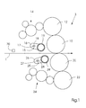
- a web 1 shows a preferred embodiment of the present invention in one Offset printing unit 3.
- a web 1 runs between two blanket cylinders 10, 20 through which flat or sleeve-shaped rubber blankets can be applied.
- the Blankets are made of printing plates applied to plate cylinders 12 and 22, respectively contacted.
- Each of the plate cylinders is moistened by means of a dampening unit 14, 24.
- the Cleaning devices 16 and 26 in line with the respective blanket cylinder 10, 20 brought. In this position, brushes 19, 29 that extend across the width of the respective blanket cylinders 10, 20 extend to the blankets.
- the Brushes 19, 29 can rotate during a cleaning process and so the Clean rubber blankets.
- spray bars 17, 27 can contain a cleaning solution, e.g. B. a solvent to spray on the brushes.
- the cleaning solution supports the Removal of accumulated paint residues and other foreign particles on the Blankets.
- the cleaning solution can also be water.
- the spray bars 17, 27 spray a liquid through openings in a respective one Spray screen 18, 28.
- the respective Spray screen 18, 28 adjusted so that the sprayed from the spray bars 17, 27 an opening happens that is essentially as wide as the web 1.
- An optical Sensor 70 can be provided to measure the web width and provide feedback to issue an automatic adjusting device for the spray diaphragms 18, 28.
- the excess cleaning solution retained by the spray orifices 18, 28 collects on the bottom of the cylindrical aperture and can be in collection devices 15, 25 are collected, which the cleaning solution in a storage container traced.
- the spray diaphragms 18, 28 can be inclined slightly at an angle or one inclined drain to collect the retained cleaning solution support.
- a preferred embodiment includes a spray screen 18 two cylinders 318, 418, each enclosing one end of the spray bar 17.
- the spray bar 17 has a plurality of outlet openings 60, which are evenly spaced across the width of the spray bar 17. Between the cylinders 318, 418 may have an unclosed portion 117 left preferably makes up a third of the width of the spray bar 17.
- the cylinders 318, 418 each have an opening 350 or 450 with an inclined edge 351 or 451.
- the Edges 351 and 451 run at an angle with respect to an axis of the spray bar 17.
- the cylinders 318 and 418 are rotatable about the spray bar 17 and z. B. by means of bearings the spray bar 17 held around.
- a device 71 for manual adjustment the cylinder 318 can be rotated so that the out of the outlet openings 62 at one Spray liquid emerging from the end of the spray bar 17 from the cylinder 318 is held back and not the brush or the blanket of the printing press reached.
- the adjusting device can 71 z. B. can be locked by means of a screw.
- the cylinder 418 can via a linkage that does not affect the outlet openings 60 with the cylinder 318 connected so that it rotates with this.
- the cylinder 418 can be be equipped with its own adjusting device.
- the web 1 usually moves in the middle of the Blanket cylinders 10, 20 between them.
- the cylinder 418 is not provided.
- the web 1 runs the side of the printing press and the blanket cylinder 10, 20 on which the cylinder is located 418 would be located.
- the width of the blanket cylinders 10, 20 reaching Spray area can be adjusted in this way by means of a single cylinder 318 become.
- Fig. 3 shows a further embodiment of the present invention, in which one Spray screen 118 has a plurality of openings 51, 52, 53, all different are wide.
- the widths preferably correspond to a customary web width.
- the Aperture 118 can be rotated with respect to the spray bar 17 as indicated by the arrow 48 and are adjusted so that the outlet openings 60 of the spray bar 17 Spray the spray liquid through the desired opening 51, 52, 53.
- the outlet openings 60 are distributed over the entire width of the spray bar 17 and preferably in a row arranged.
- FIG. 4 shows a further alternative embodiment of a spray screen 218, which is a Has opening 54 with oblique edges 55, 56. Depending on the angle of rotation the aperture 218 with respect to the spray bar 17, the spray jets from the edges 55, 56 withheld.
- the rotation of the screens 18, 118, 218 can either be done manually or by means of a automatic turning device.
- An embodiment of an automatic Rotating device is shown in Fig. 5.
- a bracket 30 of an air cylinder 31 is on the Spray bar 17 (or other fixed part) attached.
- a curve follower 32 At the other end of the Compressed air cylinder is a curve follower 32, which is in a curve 40 inside the Aperture 18 sits.
- the compressed air cylinder 31 is movable between two positions. If the compressed air cylinder 31 in the direction 57 away from the position shown in FIG. 5 moves, the curve follower 32 in the gap causes the aperture 18 in the through the direction indicated by arrow 58 rotates to a second position.
- the aperture 18 may, for. B. manually by means of a screw tensioner be moved and adjusted.
- the aperture 18, 118, 218 can be adjusted continuously or in preferred rotational positions to be movable, the z. B. by a ball catch be specified.
- the rotatable panel can also have sliding wings, by means of which the Width of the aperture can be adjusted.
- the outlet opening for the liquid was made as a variety of holes shown, but it can also be a single thin slot as an outlet opening be provided.
- the panels 18, 118, 218 are shown in the drawings in FIG shown a greater distance from the spray bar 17 than desired.
- the distance between the spray screen 18, 118, 218 and the spray bar 17 is preferably less than about 2.5 cm (1 inch), and most preferably less than 1.25 cm (0.5 inch).
- a certain distance is desired, though not absolutely necessary, with it the pressure of the spray emerging from the uncovered portion of the spray bar does not increase significantly. Such an increase in pressure could lead to more Spray liquid is applied to the blanket as desired.
Landscapes
- Inking, Control Or Cleaning Of Printing Machines (AREA)
- Cleaning By Liquid Or Steam (AREA)
- Rotary Presses (AREA)
Abstract
Description
- Fig. 1
- eine Seitenansicht eines Offsetdruckwerks mit einer erfindungsgemäßen Gummituchreinigungsvorrichtung;
- Fig. 2
- eine erste Ausführungsform der erfindungsgemäßen Vorrichtung;
- Fig. 3
- eine zweite Ausführungsform einer erfindungsgemäßen Vorrichtung;
- Fig. 4
- eine dritte Ausführungsform der erfindungsgemäßen Vorrichtung; und
- Fig. 5
- eine Detailansicht einer automatischen Stellvorrichtung für die erfindungsgemäße Vorrichtung.
- 1
- Materialbahn
- 3
- Druckwerk
- 10
- Gummituchzylinder
- 12
- Plattenzylinder
- 14
- Feuchtwerk
- 15
- Sammelvorrichtung
- 16
- Reinigungsvorrichtung
- 17
- Sprühleiste
- 18
- Sprühblende
- 19
- Bürste
- 20
- Gummituchzylinder
- 22
- Plattenzylinder
- 24
- Feuchtwerk
- 25
- Sammelvorrichtung
- 26
- Reinigungsvorrichtung
- 27
- Sprühleiste
- 28
- Sprühblende
- 29
- Bürste
- 30
- Halterung
- 31
- Druckluftzylinder
- 32
- Kurvenfolger
- 40
- Kurve
- 48
- Drehrichtung
- 51-54
- Öffnung
- 55, 56
- schräge Kante
- 57
- Bewegungsrichtung
- 58
- Drehrichtung
- 60
- Austrittsöffnung
- 62
- Austrittsöffnung
- 70
- optischer Sensor
- 71
- Vorrichtung zum manuellen Einstellen
- 117
- nicht umschlossener Bereich
- 118
- Sprühblende
- 218
- Sprühblende
- 318
- Zylinder
- 350
- Ausnehmung
- 351
- schräge Kante
- 418
- Zylinder
- 450
- Ausnehmung
- 451
- schräge Kante
Claims (17)
- Sprühvorrichtung zum Aufbringen einer Flüssigkeit, insbesondere einer Reinigungslösung, auf eine Komponente in einer Druckmaschine,
wobei die Sprühvorrichtung eine Sprühleiste (17, 27) mit wenigstens einer Austrittsöffnung (60, 62) und eine drehbare Sprühblende (18, 28, 118, 218) zum zumindest teilweisen Abdecken der wenigstens einen Austrittsöffnung (60,62) umfasst,
und wobei die Sprühleiste (17, 27) im Wesentlichen parallel zu der Komponente, insbesondere sich im Wesentlichen über die Breite der Komponente erstreckend, angeordnet ist,
dadurch gekennzeichnet, dass die Sprühblende (18, 28, 118, 218) eine im Wesentlichen parallel zur Sprühleiste (17, 27) ausgerichtete Drehachse sowie wenigstens eine Öffnung (51, 52, 53, 54, 350, 450) mit von der jeweiligen Drehposition der Sprühblende (18, 28, 118, 218) abhängiger Breite zum Einstellen der Breite eines Sprühbereichs aufweist. - Vorrichtung nach Anspruch 1,
dadurch gekennzeichnet, dass sich die wenigstens eine Austrittsöffnung (60, 62) und die wenigstens eine Öffnung an einem Ende oder an beiden Enden der Sprühleiste (60, 62) befindet, so dass eine Breite des Sprühbereichs einstellbar ist. - Vorrichtung nach Anspruch 1 oder 2,
dadurch gekennzeichnet, dass die Sprühleiste (17, 27) mindestens so breit wie die Komponente der Druckmaschine ist. - Vorrichtung nach einem der vorhergehenden Ansprüche,
dadurch gekennzeichnet, dass die Komponente der Druckmaschine als eine Reinigungsbürste (19, 29) für ein Gummituch oder als ein Gummituch einer Offsetdruckmaschine ausgebildet ist. - Vorrichtung nach einem der vorhergehenden Ansprüche,
dadurch gekennzeichnet, dass die wenigstens eine Austrittsöffnung (60, 62) als eine Vielzahl von Bohrungen ausgebildet ist, und der zu verdeckende Teil der wenigstens einen Austrittsöffnung (60, 62) mindestens eine der Bohrungen ist, die an einem Ende oder an beiden Enden der Sprühleiste (17, 27) angeordnet ist. - Vorrichtung nach Anspruch 5,
dadurch gekennzeichnet, dass die wenigstens eine Öffnung (51, 52, 53, 54, 350, 450) als eine einzige Öffnung mit mindestens einer schrägen Kante (55, 56, 351, 451) ausgebildet ist. - Vorrichtung nach einem der vorhergehenden Ansprüche,
dadurch gekennzeichnet, dass die Sprühblende (18, 28, 118, 218) zwei Zylinder (318, 418) umfasst, die jeweils eine Öffnung (350, 450) aufweisen. - Vorrichtung nach Anspruch 7,
dadurch gekennzeichnet, dass sich die beiden Zylinder (318, 418) an den jeweiligen Enden der Sprühleiste (17, 27) befinden und von einem nicht verdeckbaren Bereich (117) der Sprühvorrichtung (17, 27) getrennt sind. - Vorrichtung nach einem der vorhergehenden Ansprüche,
dadurch gekennzeichnet, dass die Sprühblende (18, 28, 118, 218) manuell einstellbar ist. - Vorrichtung nach einem der Ansprüche 1 bis 8,
gekennzeichnet durch
eine automatische Einstellvorrichtung (70) zum Einstellen der Drehposition der Sprühblenden (18, 28, 118, 218). - Vorrichtung nach Anspruch 10,
gekennzeichnet durch
einen Sensor (70) zum Ermitteln der Bahnbreite und zum Erzeugen einer Rückmeldung an die automatische Einstellvorrichtung (70). - Vorrichtung nach einem der vorhergehenden Ansprüche,
gekennzeichnet durch
eine Sammelvorrichtung (25) zum Sammeln der durch die Sprühblende (18, 28, 118, 218) zurückgehaltenen Flüssigkeit. - Offsetdruckwerk mit
einem Plattenzylinder (12, 22),
einem Gummituchzylinder (20) mit einem Gummituch, insbesondere einem zylindrischen Gummituch, welches eine auf dem Plattenzylinder (12, 22) befestigte Druckplatte kontaktiert;
gekennzeichnet durch
eine Gummituch-Reinigungsvorrichtung (16, 26), welche als Sprühvorrichtung nach einem der vorhergehenden Ansprüche ausgeführt ist. - Verfahren zum Aufbringen einer Flüssigkeit, insbesondere einer Reinigungslösung, auf eine Komponente einer Druckmaschine, wobei eine Sprühleiste (17, 27) mit wenigstens einer Austrittsöffnung (60, 62) und eine drehbare Sprühblende (18, 28, 118, 218) zum zumindest teilweisen Abdecken der wenigstens einen Austrittsöffnung (60, 62) vorgesehen sind, und wobei die Sprühleiste (17, 27) im Wesentlichen parallel zu der Komponente, insbesondere sich im Wesentlichen über die Breite der Komponente erstreckend, angeordnet ist,
gekennzeichnet durch
folgende Verfahrensschritte:Vorsehen wenigstens einer Öffnung (51, 52, 53, 54, 350, 450) in der Sprühblende (18, 28, 118, 218) mit von der jeweiligen Drehposition der Sprühblende (18, 28, 118, 218) abhängiger Breite; undDrehen der Sprühblende (18, 28, 118, 218) um eine im Wesentlichen parallel zur Sprühleiste (17, 27) ausgerichtete Drehachse zum Einstellen der Breite eines Sprühbereichs. - Verfahren nach Anspruch 14,
dadurch gekennzeichnet, dass eine Bahn (1) über die Mitte eines Gummituchzylinders (10, 20) geführt wird. - Verfahren nach Anspruch 14,
dadurch gekennzeichnet, dass eine Bahn (1) über eine Seite eines Gummituchzylinders (10, 20) geführt wird. - Druckmaschine, insbesondere Rollenrotationsdruckmaschine,
gekennzeichnet durch
wenigstens ein Offsetdruckwerk nach Anspruch 13.
Applications Claiming Priority (2)
| Application Number | Priority Date | Filing Date | Title |
|---|---|---|---|
| US09/725,617 US6484635B2 (en) | 2000-11-29 | 2000-11-29 | Variable-width spray applicator for a printing press |
| US725617 | 2000-11-29 |
Publications (2)
| Publication Number | Publication Date |
|---|---|
| EP1211071A1 true EP1211071A1 (de) | 2002-06-05 |
| EP1211071B1 EP1211071B1 (de) | 2005-09-21 |
Family
ID=24915295
Family Applications (1)
| Application Number | Title | Priority Date | Filing Date |
|---|---|---|---|
| EP01127400A Expired - Lifetime EP1211071B1 (de) | 2000-11-29 | 2001-11-23 | Sprühvorrichtung für eine Druckmaschine |
Country Status (5)
| Country | Link |
|---|---|
| US (1) | US6484635B2 (de) |
| EP (1) | EP1211071B1 (de) |
| JP (1) | JP4291969B2 (de) |
| AT (1) | ATE304943T1 (de) |
| DE (2) | DE50107479D1 (de) |
Families Citing this family (2)
| Publication number | Priority date | Publication date | Assignee | Title |
|---|---|---|---|---|
| DE10101835A1 (de) * | 2001-01-17 | 2002-07-18 | Koenig & Bauer Ag | Verfahren zum Reinigen der Oberfläche eines Zylinders |
| US20090324818A1 (en) * | 2008-06-25 | 2009-12-31 | Goss International Americas, Inc. | Silicone applicator for a printing press |
Citations (2)
| Publication number | Priority date | Publication date | Assignee | Title |
|---|---|---|---|---|
| DE943112C (de) * | 1949-04-10 | 1956-05-09 | Roland Offsetmaschf | Vorrichtung zum regelbaren Befeuchten von rotierenden Druckplatten |
| DE9109721U1 (de) * | 1991-07-27 | 1991-10-10 | Koenig & Bauer AG, 8700 Würzburg | Einrichtung zum Befeuchten von Zylindern bei Offsetrotationsdruckmaschinen |
Family Cites Families (9)
| Publication number | Priority date | Publication date | Assignee | Title |
|---|---|---|---|---|
| US2791174A (en) * | 1952-05-06 | 1957-05-07 | Roland Offsetmaschf | Device for applying liquids to cylindrical surfaces |
| DE2258321C3 (de) * | 1972-11-29 | 1981-09-17 | M.A.N. Maschinenfabrik Augsburg-Nürnberg AG, 8900 Augsburg | Vorrichtung zum Befeuchten von Druckplatten in Rotationsdruckmaschinen |
| US4831927A (en) * | 1988-05-31 | 1989-05-23 | Rockwell International Corporation | Printing press dampener |
| DE4125012A1 (de) * | 1991-07-27 | 1993-01-28 | Koenig & Bauer Ag | Einrichtung zum befeuchten von zylindern bei offsetrotationsdruckmaschinen |
| US5259313A (en) | 1991-12-20 | 1993-11-09 | Heidelberg Harris Gmbh | Method and apparatus for cleaning an inking mechanism and/or a printing mechanism in printing units of rotary printing machines |
| US5257578A (en) | 1993-01-12 | 1993-11-02 | Heidelberger Druckmaschinen Ag | Device for automatically cleaning blanket cylinders in a offset printing press |
| DE4301410A1 (de) | 1993-01-20 | 1994-07-21 | Baldwin Gegenheimer Gmbh | Druckmaschinen-Reinigungsvorrichtung |
| SE507912C2 (sv) * | 1993-04-23 | 1998-07-27 | Jimek Int Ab | Sprayfuktverk för en tryckpress |
| US5490459A (en) | 1995-02-24 | 1996-02-13 | Heidelberger Druckmaschinen Ag | Printing press and method for removing ink build-up with sideways web movement |
-
2000
- 2000-11-29 US US09/725,617 patent/US6484635B2/en not_active Expired - Fee Related
-
2001
- 2001-11-23 AT AT01127400T patent/ATE304943T1/de not_active IP Right Cessation
- 2001-11-23 DE DE50107479T patent/DE50107479D1/de not_active Expired - Lifetime
- 2001-11-23 EP EP01127400A patent/EP1211071B1/de not_active Expired - Lifetime
- 2001-11-23 DE DE10157501A patent/DE10157501A1/de not_active Withdrawn
- 2001-11-29 JP JP2001364926A patent/JP4291969B2/ja not_active Expired - Fee Related
Patent Citations (2)
| Publication number | Priority date | Publication date | Assignee | Title |
|---|---|---|---|---|
| DE943112C (de) * | 1949-04-10 | 1956-05-09 | Roland Offsetmaschf | Vorrichtung zum regelbaren Befeuchten von rotierenden Druckplatten |
| DE9109721U1 (de) * | 1991-07-27 | 1991-10-10 | Koenig & Bauer AG, 8700 Würzburg | Einrichtung zum Befeuchten von Zylindern bei Offsetrotationsdruckmaschinen |
Also Published As
| Publication number | Publication date |
|---|---|
| JP4291969B2 (ja) | 2009-07-08 |
| DE10157501A1 (de) | 2002-07-18 |
| JP2002192704A (ja) | 2002-07-10 |
| US6484635B2 (en) | 2002-11-26 |
| EP1211071B1 (de) | 2005-09-21 |
| ATE304943T1 (de) | 2005-10-15 |
| DE50107479D1 (de) | 2005-10-27 |
| US20020062754A1 (en) | 2002-05-30 |
Similar Documents
| Publication | Publication Date | Title |
|---|---|---|
| DE2815388C3 (de) | Vorrichtung zum Waschen von Zylindern an Druckmaschinen, insbesondere Offsetdruckmaschinen | |
| DE19624536B4 (de) | Abstreichmesser und Farbabführvorrichtung für Druckmaschinen | |
| EP1338418B1 (de) | Druckmaschine mit Vorrichtung zur Klischeereinigung | |
| DE2531886C3 (de) | Verfahren und Vorrichtung zur Reinigung von Zylindern eines Offsetdruckwerkes | |
| DE4238201A1 (de) | ||
| DE10209091A1 (de) | Vorrichtung zur Reinigung wenigstens eines ausgewählten Abschnittes einer Zylinderoberfläche | |
| DE69118587T2 (de) | Waschvorrichtung mit rotierender Bürste | |
| DE69405824T2 (de) | Farbwerk für Druckmaschinen | |
| EP0351562B1 (de) | Vorrichtung zum Reinigen eines Plattenzylinders und eines Gummituchzylinders einer Offsetdruckmaschine | |
| DE3843473C2 (de) | Feuchtwerk | |
| EP0606581B1 (de) | Vorrichtung zum automatischen Reinigen von Gummituchzylindern in einer Offsetdruckmaschine | |
| DE19547607A1 (de) | Druckmaschine und Verfahren zum Beseitigen von Farbaufbau | |
| EP1211071B1 (de) | Sprühvorrichtung für eine Druckmaschine | |
| DE19625030A1 (de) | Offsetdruckvorrichtung für Rotationsdruckmaschinen | |
| DE19942617A1 (de) | Vorrichtung und Verfahren zur Durchführung eines fliegenden Plattenwechsels | |
| EP0711666B1 (de) | Reinigungseinrichtung für eine Bogenleiteinrichtung einer Rotationsdruckmaschine | |
| DD274003A1 (de) | Rakeleinrichtung fuer offsetdruckmaschinen | |
| DE10025453A1 (de) | Nummerier-und Eindruckwerk an Druckmaschinen | |
| EP0770483B1 (de) | Waschvorrichtung zur Reinigung von Zylindern eines Offsetdruckwerkes | |
| EP0909648B1 (de) | Vorrichtung zum Reinigen von Zylindern einer Druckmaschine | |
| CH657313A5 (en) | Method for operating a web-fed rotary press | |
| DE3933677C2 (de) | ||
| EP1817167B1 (de) | Tiefdruckwerk mit einem abstreifer für den formzylinder, tiefdruckmaschine und verfahren zum austausch eines formzylinders | |
| EP1525094A1 (de) | Druckmaschine und verfahren zum bedrucken von zwei bahnen | |
| EP1188559A1 (de) | Einrichtung zum Bebildern von zylindrischen Oberflächen in Druckmaschinen |
Legal Events
| Date | Code | Title | Description |
|---|---|---|---|
| PUAI | Public reference made under article 153(3) epc to a published international application that has entered the european phase |
Free format text: ORIGINAL CODE: 0009012 |
|
| 17P | Request for examination filed |
Effective date: 20020318 |
|
| AK | Designated contracting states |
Kind code of ref document: A1 Designated state(s): AT BE CH CY DE DK ES FI FR GB GR IE IT LI LU MC NL PT SE TR |
|
| AX | Request for extension of the european patent |
Free format text: AL;LT;LV;MK;RO;SI |
|
| AKX | Designation fees paid |
Designated state(s): AT BE CH CY DE DK ES FI FR GB GR IE IT LI LU MC NL PT SE TR |
|
| RAP1 | Party data changed (applicant data changed or rights of an application transferred) |
Owner name: GOSS INTERNATIONAL AMERICAS, INC. |
|
| GRAP | Despatch of communication of intention to grant a patent |
Free format text: ORIGINAL CODE: EPIDOSNIGR1 |
|
| GRAS | Grant fee paid |
Free format text: ORIGINAL CODE: EPIDOSNIGR3 |
|
| GRAA | (expected) grant |
Free format text: ORIGINAL CODE: 0009210 |
|
| AK | Designated contracting states |
Kind code of ref document: B1 Designated state(s): AT BE CH CY DE DK ES FI FR GB GR IE IT LI LU MC NL PT SE TR |
|
| PG25 | Lapsed in a contracting state [announced via postgrant information from national office to epo] |
Ref country code: IT Free format text: LAPSE BECAUSE OF FAILURE TO SUBMIT A TRANSLATION OF THE DESCRIPTION OR TO PAY THE FEE WITHIN THE PRESCRIBED TIME-LIMIT;WARNING: LAPSES OF ITALIAN PATENTS WITH EFFECTIVE DATE BEFORE 2007 MAY HAVE OCCURRED AT ANY TIME BEFORE 2007. THE CORRECT EFFECTIVE DATE MAY BE DIFFERENT FROM THE ONE RECORDED. Effective date: 20050921 Ref country code: TR Free format text: LAPSE BECAUSE OF FAILURE TO SUBMIT A TRANSLATION OF THE DESCRIPTION OR TO PAY THE FEE WITHIN THE PRESCRIBED TIME-LIMIT Effective date: 20050921 Ref country code: NL Free format text: LAPSE BECAUSE OF FAILURE TO SUBMIT A TRANSLATION OF THE DESCRIPTION OR TO PAY THE FEE WITHIN THE PRESCRIBED TIME-LIMIT Effective date: 20050921 Ref country code: IE Free format text: LAPSE BECAUSE OF FAILURE TO SUBMIT A TRANSLATION OF THE DESCRIPTION OR TO PAY THE FEE WITHIN THE PRESCRIBED TIME-LIMIT Effective date: 20050921 Ref country code: FI Free format text: LAPSE BECAUSE OF FAILURE TO SUBMIT A TRANSLATION OF THE DESCRIPTION OR TO PAY THE FEE WITHIN THE PRESCRIBED TIME-LIMIT Effective date: 20050921 |
|
| REG | Reference to a national code |
Ref country code: GB Ref legal event code: FG4D Free format text: NOT ENGLISH |
|
| REG | Reference to a national code |
Ref country code: CH Ref legal event code: EP |
|
| GBT | Gb: translation of ep patent filed (gb section 77(6)(a)/1977) |
Effective date: 20050921 |
|
| REG | Reference to a national code |
Ref country code: IE Ref legal event code: FG4D Free format text: LANGUAGE OF EP DOCUMENT: GERMAN |
|
| REF | Corresponds to: |
Ref document number: 50107479 Country of ref document: DE Date of ref document: 20051027 Kind code of ref document: P |
|
| PG25 | Lapsed in a contracting state [announced via postgrant information from national office to epo] |
Ref country code: CY Free format text: LAPSE BECAUSE OF FAILURE TO SUBMIT A TRANSLATION OF THE DESCRIPTION OR TO PAY THE FEE WITHIN THE PRESCRIBED TIME-LIMIT Effective date: 20051123 Ref country code: AT Free format text: LAPSE BECAUSE OF NON-PAYMENT OF DUE FEES Effective date: 20051123 |
|
| PG25 | Lapsed in a contracting state [announced via postgrant information from national office to epo] |
Ref country code: LU Free format text: LAPSE BECAUSE OF NON-PAYMENT OF DUE FEES Effective date: 20051130 Ref country code: MC Free format text: LAPSE BECAUSE OF NON-PAYMENT OF DUE FEES Effective date: 20051130 Ref country code: BE Free format text: LAPSE BECAUSE OF NON-PAYMENT OF DUE FEES Effective date: 20051130 |
|
| PG25 | Lapsed in a contracting state [announced via postgrant information from national office to epo] |
Ref country code: DK Free format text: LAPSE BECAUSE OF FAILURE TO SUBMIT A TRANSLATION OF THE DESCRIPTION OR TO PAY THE FEE WITHIN THE PRESCRIBED TIME-LIMIT Effective date: 20051221 Ref country code: SE Free format text: LAPSE BECAUSE OF FAILURE TO SUBMIT A TRANSLATION OF THE DESCRIPTION OR TO PAY THE FEE WITHIN THE PRESCRIBED TIME-LIMIT Effective date: 20051221 Ref country code: GR Free format text: LAPSE BECAUSE OF FAILURE TO SUBMIT A TRANSLATION OF THE DESCRIPTION OR TO PAY THE FEE WITHIN THE PRESCRIBED TIME-LIMIT Effective date: 20051221 |
|
| REG | Reference to a national code |
Ref country code: CH Ref legal event code: NV Representative=s name: KIRKER & CIE SA |
|
| PG25 | Lapsed in a contracting state [announced via postgrant information from national office to epo] |
Ref country code: ES Free format text: LAPSE BECAUSE OF FAILURE TO SUBMIT A TRANSLATION OF THE DESCRIPTION OR TO PAY THE FEE WITHIN THE PRESCRIBED TIME-LIMIT Effective date: 20060101 |
|
| PG25 | Lapsed in a contracting state [announced via postgrant information from national office to epo] |
Ref country code: PT Free format text: LAPSE BECAUSE OF FAILURE TO SUBMIT A TRANSLATION OF THE DESCRIPTION OR TO PAY THE FEE WITHIN THE PRESCRIBED TIME-LIMIT Effective date: 20060221 |
|
| NLV1 | Nl: lapsed or annulled due to failure to fulfill the requirements of art. 29p and 29m of the patents act | ||
| REG | Reference to a national code |
Ref country code: IE Ref legal event code: FD4D |
|
| PLBE | No opposition filed within time limit |
Free format text: ORIGINAL CODE: 0009261 |
|
| STAA | Information on the status of an ep patent application or granted ep patent |
Free format text: STATUS: NO OPPOSITION FILED WITHIN TIME LIMIT |
|
| 26N | No opposition filed |
Effective date: 20060622 |
|
| PG25 | Lapsed in a contracting state [announced via postgrant information from national office to epo] |
Ref country code: FR Free format text: LAPSE BECAUSE OF FAILURE TO SUBMIT A TRANSLATION OF THE DESCRIPTION OR TO PAY THE FEE WITHIN THE PRESCRIBED TIME-LIMIT Effective date: 20061020 |
|
| EN | Fr: translation not filed | ||
| BERE | Be: lapsed |
Owner name: GOSS INTERNATIONAL AMERICAS, INC. Effective date: 20051130 |
|
| PG25 | Lapsed in a contracting state [announced via postgrant information from national office to epo] |
Ref country code: FR Free format text: LAPSE BECAUSE OF FAILURE TO SUBMIT A TRANSLATION OF THE DESCRIPTION OR TO PAY THE FEE WITHIN THE PRESCRIBED TIME-LIMIT Effective date: 20051130 |
|
| PG25 | Lapsed in a contracting state [announced via postgrant information from national office to epo] |
Ref country code: FR Free format text: LAPSE BECAUSE OF FAILURE TO SUBMIT A TRANSLATION OF THE DESCRIPTION OR TO PAY THE FEE WITHIN THE PRESCRIBED TIME-LIMIT Effective date: 20050921 |
|
| PGFP | Annual fee paid to national office [announced via postgrant information from national office to epo] |
Ref country code: DE Payment date: 20101126 Year of fee payment: 10 Ref country code: CH Payment date: 20101124 Year of fee payment: 10 |
|
| PGFP | Annual fee paid to national office [announced via postgrant information from national office to epo] |
Ref country code: GB Payment date: 20101124 Year of fee payment: 10 |
|
| REG | Reference to a national code |
Ref country code: CH Ref legal event code: PL |
|
| GBPC | Gb: european patent ceased through non-payment of renewal fee |
Effective date: 20111123 |
|
| PG25 | Lapsed in a contracting state [announced via postgrant information from national office to epo] |
Ref country code: CH Free format text: LAPSE BECAUSE OF NON-PAYMENT OF DUE FEES Effective date: 20111130 Ref country code: LI Free format text: LAPSE BECAUSE OF NON-PAYMENT OF DUE FEES Effective date: 20111130 |
|
| REG | Reference to a national code |
Ref country code: DE Ref legal event code: R119 Ref document number: 50107479 Country of ref document: DE Effective date: 20120601 |
|
| PG25 | Lapsed in a contracting state [announced via postgrant information from national office to epo] |
Ref country code: GB Free format text: LAPSE BECAUSE OF NON-PAYMENT OF DUE FEES Effective date: 20111123 |
|
| PG25 | Lapsed in a contracting state [announced via postgrant information from national office to epo] |
Ref country code: DE Free format text: LAPSE BECAUSE OF NON-PAYMENT OF DUE FEES Effective date: 20120601 |