EP1208297B1 - Einspritzventil für eine verbrennungskraftmaschine - Google Patents
Einspritzventil für eine verbrennungskraftmaschine Download PDFInfo
- Publication number
- EP1208297B1 EP1208297B1 EP00936814A EP00936814A EP1208297B1 EP 1208297 B1 EP1208297 B1 EP 1208297B1 EP 00936814 A EP00936814 A EP 00936814A EP 00936814 A EP00936814 A EP 00936814A EP 1208297 B1 EP1208297 B1 EP 1208297B1
- Authority
- EP
- European Patent Office
- Prior art keywords
- actuating
- valve
- injection valve
- valve according
- face
- Prior art date
- Legal status (The legal status is an assumption and is not a legal conclusion. Google has not performed a legal analysis and makes no representation as to the accuracy of the status listed.)
- Expired - Lifetime
Links
- 238000002347 injection Methods 0.000 title claims abstract description 52
- 239000007924 injection Substances 0.000 title claims abstract description 52
- 238000002485 combustion reaction Methods 0.000 title claims abstract description 5
- 238000007789 sealing Methods 0.000 claims abstract description 61
- 239000012530 fluid Substances 0.000 claims description 22
- 235000001674 Agaricus brunnescens Nutrition 0.000 claims description 9
- 230000005489 elastic deformation Effects 0.000 claims description 4
- 230000037431 insertion Effects 0.000 claims 5
- 238000003780 insertion Methods 0.000 claims 5
- 238000000926 separation method Methods 0.000 abstract description 2
- 230000006870 function Effects 0.000 description 6
- 230000008901 benefit Effects 0.000 description 5
- 238000013016 damping Methods 0.000 description 4
- 239000000463 material Substances 0.000 description 4
- 230000006835 compression Effects 0.000 description 3
- 238000007906 compression Methods 0.000 description 3
- 238000000034 method Methods 0.000 description 3
- 230000008859 change Effects 0.000 description 2
- 230000000694 effects Effects 0.000 description 2
- 238000004519 manufacturing process Methods 0.000 description 2
- 230000008569 process Effects 0.000 description 2
- 238000005452 bending Methods 0.000 description 1
- 238000004891 communication Methods 0.000 description 1
- 238000010276 construction Methods 0.000 description 1
- 230000003111 delayed effect Effects 0.000 description 1
- 238000005516 engineering process Methods 0.000 description 1
- 239000000446 fuel Substances 0.000 description 1
- 230000006872 improvement Effects 0.000 description 1
- 230000001739 rebound effect Effects 0.000 description 1
- 230000000284 resting effect Effects 0.000 description 1
- 238000004904 shortening Methods 0.000 description 1
- 239000000126 substance Substances 0.000 description 1
- 230000001960 triggered effect Effects 0.000 description 1
Images


Classifications
-
- F—MECHANICAL ENGINEERING; LIGHTING; HEATING; WEAPONS; BLASTING
- F02—COMBUSTION ENGINES; HOT-GAS OR COMBUSTION-PRODUCT ENGINE PLANTS
- F02M—SUPPLYING COMBUSTION ENGINES IN GENERAL WITH COMBUSTIBLE MIXTURES OR CONSTITUENTS THEREOF
- F02M63/00—Other fuel-injection apparatus having pertinent characteristics not provided for in groups F02M39/00 - F02M57/00 or F02M67/00; Details, component parts, or accessories of fuel-injection apparatus, not provided for in, or of interest apart from, the apparatus of groups F02M39/00 - F02M61/00 or F02M67/00; Combination of fuel pump with other devices, e.g. lubricating oil pump
- F02M63/0012—Valves
- F02M63/0031—Valves characterized by the type of valves, e.g. special valve member details, valve seat details, valve housing details
- F02M63/0033—Lift valves, i.e. having a valve member that moves perpendicularly to the plane of the valve seat
-
- F—MECHANICAL ENGINEERING; LIGHTING; HEATING; WEAPONS; BLASTING
- F02—COMBUSTION ENGINES; HOT-GAS OR COMBUSTION-PRODUCT ENGINE PLANTS
- F02M—SUPPLYING COMBUSTION ENGINES IN GENERAL WITH COMBUSTIBLE MIXTURES OR CONSTITUENTS THEREOF
- F02M47/00—Fuel-injection apparatus operated cyclically with fuel-injection valves actuated by fluid pressure
- F02M47/02—Fuel-injection apparatus operated cyclically with fuel-injection valves actuated by fluid pressure of accumulator-injector type, i.e. having fuel pressure of accumulator tending to open, and fuel pressure in other chamber tending to close, injection valves and having means for periodically releasing that closing pressure
- F02M47/027—Electrically actuated valves draining the chamber to release the closing pressure
-
- F—MECHANICAL ENGINEERING; LIGHTING; HEATING; WEAPONS; BLASTING
- F02—COMBUSTION ENGINES; HOT-GAS OR COMBUSTION-PRODUCT ENGINE PLANTS
- F02M—SUPPLYING COMBUSTION ENGINES IN GENERAL WITH COMBUSTIBLE MIXTURES OR CONSTITUENTS THEREOF
- F02M63/00—Other fuel-injection apparatus having pertinent characteristics not provided for in groups F02M39/00 - F02M57/00 or F02M67/00; Details, component parts, or accessories of fuel-injection apparatus, not provided for in, or of interest apart from, the apparatus of groups F02M39/00 - F02M61/00 or F02M67/00; Combination of fuel pump with other devices, e.g. lubricating oil pump
- F02M63/0012—Valves
- F02M63/0014—Valves characterised by the valve actuating means
- F02M63/0015—Valves characterised by the valve actuating means electrical, e.g. using solenoid
- F02M63/0017—Valves characterised by the valve actuating means electrical, e.g. using solenoid using electromagnetic operating means
-
- F—MECHANICAL ENGINEERING; LIGHTING; HEATING; WEAPONS; BLASTING
- F02—COMBUSTION ENGINES; HOT-GAS OR COMBUSTION-PRODUCT ENGINE PLANTS
- F02M—SUPPLYING COMBUSTION ENGINES IN GENERAL WITH COMBUSTIBLE MIXTURES OR CONSTITUENTS THEREOF
- F02M63/00—Other fuel-injection apparatus having pertinent characteristics not provided for in groups F02M39/00 - F02M57/00 or F02M67/00; Details, component parts, or accessories of fuel-injection apparatus, not provided for in, or of interest apart from, the apparatus of groups F02M39/00 - F02M61/00 or F02M67/00; Combination of fuel pump with other devices, e.g. lubricating oil pump
- F02M63/0012—Valves
- F02M63/007—Details not provided for in, or of interest apart from, the apparatus of the groups F02M63/0014 - F02M63/0059
- F02M63/0078—Valve member details, e.g. special shape, hollow or fuel passages in the valve member
Definitions
- the invention relates to an injection valve for an internal combustion engine with an electromagnetically actuated control valve, which by means of a valve actuator alternatively closes a fluid passage opening associated with a sealing surface or releases and thereby the pressure in a connected to the passage opening Control pressure chamber controls.
- FIG. 2 of the European Patent EP 0531 533 B1 An injection valve with the aforementioned features is shown in FIG. 2 of the European Patent EP 0531 533 B1.
- Valve actuator firmly connected to the armature of the electromagnet and is through Spring force pressed on a sealing surface, so that the passage opening for Control pressure chamber is closed.
- injectors are at Memory injection systems used where very high control pressures of the order several 100 bar occur.
- valve actuator By switching off the solenoid current the armature strikes and with this usually the cylindrical bolt executed valve actuator with its end face under the spring force on the sealing surface and thus closes the passage opening.
- a good sealing effect of the valve actuator against the very high pressure in the control pressure chamber is by as small as possible Cross-sectional area and thus achieved small diameter of the valve actuator.
- One The smallest possible diameter of the valve actuator is therefore also desirable, so Angle error, d. H. Deviations in the orientation of the end face of the valve actuator from the associated sealing seat surface caused by manufacturing inaccuracies, not lead to leakage gaps.
- a third reason for the least possible Diameter of the valve actuator a high aspired sealing seat pressure and thus a more precise control.
- a disadvantage of a small diameter of the valve actuator is that with a small diameter and thus smaller face a possibly inadmissible high seat impact at the valve opening results.
- Another disadvantage of a low Diameter of the valve actuator can be seen in the fact that the closing movement of Magnetic armature and the valve actuator, which together create a considerable inertial mass form, little steamed to be delayed to zero and so rebound effects occur. For a damping braking of the valve actuator would be the largest possible diameter and thus a correspondingly large end face desirable.
- the anchor plate can by suitable adjustment of the size of the free path of the Anchor plate and the return spring done.
- the wear of the sealing surface is characterized reduced that the mass forces are reduced.
- the forces acting in the sealing surface However, they depend on dynamic processes, so that a defined sealing force can not be set.
- Object of the present invention is inadmissible high wear by the Avoid impact movement of the valve actuator by the in the sealing surface acting sealing forces to a predetermined fixed, independent of the operation value be set.
- the object is achieved by a device according to claim 1.
- the Actuator stop surface is substantially larger than the actuator sealing surface.
- the local separate training of actuator stop surface and actuator sealing surface has about addition, the advantage that high fluid pressures, as in the field of Fluid passage opening and thus the actuator sealing surface occur locally from Electromagnets can be moved away and so far the electromagnet of high hydraulic pressure is protected.
- Another advantage is that the Electromagnet also from interference by the physical or chemical Properties of the control fluid can be better protected.
- an injection valve according to the invention that is Valve actuator formed with a one-piece or multi-part valve rod.
- valve actuator comprises a spherical Valve body, which rests on the front side of the valve stem and with conical Sealing surfaces of the passage opening cooperates.
- actuator sealing surface but can also serve directly the front side of the valve stem.
- the length of the valve rod is determined essentially by the distance, the Actuator sealing surface or the valve body stop of the valve stem of the Actuator stop surface has.
- valve actuator is designed substantially mushroom-shaped, wherein the mushroom shaft forms the valve rod and the actuator stop surface in the area of Mushroom hat the valve stem is concentric surrounding collar.
- the Length of the valve stem is larger by a minimum amount than the distance Sealing surface of the fluid passage opening or the valve body stop of the valve rod from the reference stop for the actuator stop surface.
- a preferred embodiment of the invention is characterized in that the Valve actuator in the actuator stop surface having actuator stop and one operatively connected to the actuator sealing surface and the actuator stop Valve rod is split.
- Valve actuator is that the significantly smaller in diameter valve stem easier to produce independently of the actuator stop. Another advantage is that uses different material for the valve rod and the actuator stop can be. In the split version of the valve actuator only needs ensure that the opening movement of the valve stem, d. H. So the take off from the sealing surface by the overpressure from the fluid passage opening or by a supporting auxiliary spring is ensured. The slight excess length of the valve stem, based on the distance between the actuator sealing surface or valve body stop and the actuator stopper surface (valve rod protrusion) becomes the closing movement absorbed by elastic deformation (shortening) of the valve rod.
- the actuator stop is designed substantially mushroom-shaped, wherein the actuator stop surface in the area of the mushroom foot on the valve rod striking end face is.
- This face will normally be a circular area whose Diameter is significantly larger than the diameter of the abutting valve rod.
- valve stem in To guide guide bushes axially movable. It is with regard to a possible minimum actuator sealing surface to aim for a guide bush in low Distance of the actuator sealing surface of the valve rod is arranged. That way Bending vibrations of the free end of the valve stem with the actuator sealing surface prevented, so that the actuator sealing surface only a slightly larger diameter must have as the passage bore.
- the length of the valve rod is preferably a multiple of its diameter.
- the actuator sealing surface is a one- or two-part associated disc-shaped insert part, wherein on the side facing away from the sealing surface the control pressure chamber connects.
- the corresponding Einlegteil can with little Expenditure material adapted to different claim cases and thereby the Gasket be improved.
- inflow and Outflow throttle can be assigned to different parts, in a simple manner to meet different requirements in the injection characteristics.
- the injection valve shown in Fig. 1 of a high-pressure accumulator injection system for a Internal combustion engine has a housing 1. At the bottom of the Injection valve is a valve needle 20 mounted by the axial movement of a Injection hole 24 can be released from a high-pressure chamber 21 and thus an injection takes place.
- the high-pressure chamber 21 communicates with channels in the housing 1 a high pressure port 22 in conjunction.
- the control of the movement of Nozzle needle 20 via an electromagnet 10, the armature 11 with a Valve actuator 12 is firmly connected.
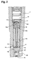
- the valve actuator 12 is part of a control valve, which is actuated by the electromagnet 10. The function of this Electromagnetically actuated control valve is based on the magnification of FIG. 2 explained.
- the Valve actuator 12 is designed substantially mushroom-shaped, wherein the mushroom shaft as Valve rod 16 is formed, which extends from the region of the mushroom hat to a sealing surface 17th ranges, in which a fluid passage opening 14a from a control pressure chamber 14 opens.
- the Diameter of the valve rod 16 is chosen so that the end face the Fluid passage opening 14a just covered and thus on the sealing surface 17 a Forms sealing seat. It can easily be seen that the length of the valve rod 16 a Multiple of its diameter.
- the control pressure chamber 14 is above a Orifice communicates with the high pressure port system of the injector.
- the Valve actuator 12 is through the valve rod 16 in an upper guide sleeve 15o and a lower guide sleeve 15u mounted on the housing side axially displaceable. It is the bottom guide bush 15u arranged so that only a small distance between the lower end of the valve rod 16, which is designed as an actuator sealing surface 16 a, and the lower edge of the lower guide sleeve 15u remains. The resulting there Annulus 18 communicates with a low pressure fluid port 19 of the injector Connection. In the closed position of the electromagnetic shown in Fig. 2 Control valve closes the valve rod 16 with its actuator sealing surface 16 a the Fluid passage bore 14 a from.
- Valve rod 16 concentrically surrounding annular collar is as an actuator stop surface 12a trained and resting on the upper plane of the sleeve 15o.
- the valve actuator 12th together with the armature 11 by a compression spring, not shown loaded, the actuator 12 on the sealing surface 17 and at the same time on the top of the upper guide sleeve 15o presses, which as a reference stop for the Actuator stop surface 12a of the actuator 12 is used.
- FIG. 3 This danger is based on the greatly enlarged view of FIG. 3 at a conventional injection valve shown.
- a valve is similar in construction shown in Fig. 1 and Fig. 2, but with the difference that the fluid passage opening 14a, which is in communication with the control pressure chamber 14, up to one, the function of a Stop and sealing surface having housing surface 13 is guided.
- the valve actuator 12 is again mushroom-shaped, but does not have the inventive Valve rod 16.
- the diameter e of the sealing seat and impact surface is clear chosen larger than the diameter of the fluid passage bore 14a. The must Danger be accepted that due to an angular error f, d. H.
- FIG. 4 shows a region of an injection valve corresponding to FIG Area of the actuator sealing surface is modified.
- the valve rod 16 acts as in FIG. 4 shown enlarged, on a valve body 30 which is formed as a ball.
- a valve body 30 which is formed as a ball.
- the fluid passage opening 14a includes a Outflow throttle 33.
- the use of a separate valve body 30, which is also a other than having a spherical shape, has the advantage that the seal is improved.
- valve rod 16 and valve body 30th to use different materials.
- Another improvement of the seal results from using an insert in the form of a disk-shaped part 37, which contains the outflow throttle 33.
- This part 37 may be in terms of material and Throttle bore in a simple manner optimally to different load cases be matched. By providing inserts with different sizes Throttle holes, it is possible in the other by simple exchange, the Change injection characteristics. It is also possible second parts 34 with provide different Zufichdrosseln 36 to the simple replacement of the To tune injection characteristics. This procedure, the injection quantity and the Injection process by replacing first and second inserts with different Chokes to change is known per se from EP 0 844 385 A1.
- the part 37 is through a centering and retaining clip 39 connected to a sleeve 38 in which the valve rod 16 is recorded with their guide bushes 15o and 15u.
- FIG. 5 shows an inventive injection valve, which also a disc-shaped insert 32 includes.
- the Einlegteils 32 connects directly to the control pressure chamber 14.
- the nozzle needle 20 lies with its rear end directly in the control pressure chamber 14.
- the Einlegteil 32nd is installed between the nozzle holder and the injection nozzle 40. Injector 40 and Einlegteil 32 are pressed by a nozzle nut to the nozzle holder, so that the high pressure leading areas are interconnected.
- the insert 32 has a Central bore as the fluid passage opening 14a to the control pressure chamber 14 and in the Valve rod 16 opposite area a calibrated outflow throttle 33.
- the Einlegteil also includes a high-pressure passage 41, which under the injection pressure standing fuel from a high pressure port 22 to a high pressure passage in the Injecting nozzle passes.
- the high pressure passage 41 in the Einlegteil 32 has a Line connection to the center hole in Einlegteil 32 and in this line connection there is a calibrated inlet throttle 36.
- the insert 32 has as shown in Figure 4, a conical sealing surface 17, in which a spherical valve body 30 concerned the seal.
- a corresponding embodiment is in itself from the US 5,832,899 known.
- the injector corresponds to the injector described under FIG. 1 or FIG. 2. Due to the design with the two sides of the insert directly assigned Control spaces, the seal is essentially reduced to this area, the easy can be mastered. In particular, it is by providing suitable Einlegteil in easy way possible to different load cases and requirements Injection quantity and injection course to react.
Landscapes
- Engineering & Computer Science (AREA)
- Chemical & Material Sciences (AREA)
- Combustion & Propulsion (AREA)
- Mechanical Engineering (AREA)
- General Engineering & Computer Science (AREA)
- Physics & Mathematics (AREA)
- Fluid Mechanics (AREA)
- Electromagnetism (AREA)
- Fuel-Injection Apparatus (AREA)
- Magnetically Actuated Valves (AREA)
- Valve-Gear Or Valve Arrangements (AREA)
Applications Claiming Priority (3)
| Application Number | Priority Date | Filing Date | Title |
|---|---|---|---|
| DE19938921A DE19938921B4 (de) | 1999-08-17 | 1999-08-17 | Einspritzventil für eine Verbrennungskraftmaschine |
| DE19938921 | 1999-08-17 | ||
| PCT/EP2000/004815 WO2001012981A1 (de) | 1999-08-17 | 2000-05-26 | Einspritzventil für eine verbrennungskraftmaschine |
Publications (2)
| Publication Number | Publication Date |
|---|---|
| EP1208297A1 EP1208297A1 (de) | 2002-05-29 |
| EP1208297B1 true EP1208297B1 (de) | 2005-03-30 |
Family
ID=7918638
Family Applications (1)
| Application Number | Title | Priority Date | Filing Date |
|---|---|---|---|
| EP00936814A Expired - Lifetime EP1208297B1 (de) | 1999-08-17 | 2000-05-26 | Einspritzventil für eine verbrennungskraftmaschine |
Country Status (5)
| Country | Link |
|---|---|
| EP (1) | EP1208297B1 (https=) |
| JP (1) | JP3754649B2 (https=) |
| AT (1) | ATE292239T1 (https=) |
| DE (2) | DE19938921B4 (https=) |
| WO (1) | WO2001012981A1 (https=) |
Cited By (1)
| Publication number | Priority date | Publication date | Assignee | Title |
|---|---|---|---|---|
| DE102007025050B3 (de) * | 2007-05-29 | 2008-10-16 | L'orange Gmbh | Hochdruck-Einspritzinjektor für Brennkraftmaschinen mit einer knicklaststeigernden Steuerstangenabstützung über unter Hochdruck stehendem Kraftstoff |
Families Citing this family (3)
| Publication number | Priority date | Publication date | Assignee | Title |
|---|---|---|---|---|
| DE10147830B4 (de) * | 2001-09-27 | 2008-05-08 | L'orange Gmbh | Kraftstoffinjektor |
| DE10212002C1 (de) * | 2002-03-18 | 2003-08-21 | Orange Gmbh | Einspritzinjektor für Brennkraftmaschinen |
| DE50302779D1 (de) | 2002-03-18 | 2006-05-18 | Orange Gmbh | Einspritzinjektor für Brennkraftmaschinen |
Family Cites Families (14)
| Publication number | Priority date | Publication date | Assignee | Title |
|---|---|---|---|---|
| EP0531533B1 (en) | 1991-01-14 | 1997-03-19 | Nippondenso Co., Ltd. | Pressure accumulation type fuel jetting device |
| JP3076118B2 (ja) | 1991-11-27 | 2000-08-14 | シスメックス株式会社 | 粒子計数方法 |
| JPH06193531A (ja) * | 1992-10-28 | 1994-07-12 | Zexel Corp | 燃料噴射装置 |
| US5524825A (en) * | 1993-09-28 | 1996-06-11 | Zexel Corporation | Unit type fuel injector for internal combustion engines |
| DE4336108C1 (de) * | 1993-10-22 | 1994-12-01 | Daimler Benz Ag | Magnetvenitl an einer für Brennkraftmaschinen vorgesehenen Kraftstoffeinspritzdüse |
| EP0745764B1 (de) * | 1995-06-02 | 2001-03-21 | Ganser-Hydromag Ag | Brennstoffeinspritzventil für Verbrennungskraftmaschinen |
| IT1276503B1 (it) * | 1995-07-14 | 1997-10-31 | Elasis Sistema Ricerca Fiat | Perfezionamenti ad una valvola di dosaggio a comando elettromagnetico, per un iniettore di combustibile. |
| GB9520243D0 (en) | 1995-10-04 | 1995-12-06 | Lucas Ind Plc | Injector |
| JP3719461B2 (ja) * | 1996-11-25 | 2005-11-24 | 株式会社デンソー | 蓄圧式燃料噴射装置 |
| JP3755143B2 (ja) * | 1996-11-21 | 2006-03-15 | 株式会社デンソー | 蓄圧式燃料噴射装置 |
| DE69719461T2 (de) * | 1996-11-21 | 2004-01-15 | Denso Corp | Speicherkraftstoffeinspritzvorrichtung für Verbrennungsmotor |
| DE19650865A1 (de) * | 1996-12-07 | 1998-06-10 | Bosch Gmbh Robert | Magnetventil |
| DE19708104A1 (de) * | 1997-02-28 | 1998-09-03 | Bosch Gmbh Robert | Magnetventil |
| IT1296144B1 (it) * | 1997-11-18 | 1999-06-09 | Elasis Sistema Ricerca Fiat | Valvola di dosaggio registrabile per un iniettore di combustibile per motori a combustione interna. |
-
1999
- 1999-08-17 DE DE19938921A patent/DE19938921B4/de not_active Expired - Fee Related
-
2000
- 2000-05-26 JP JP2001517048A patent/JP3754649B2/ja not_active Expired - Lifetime
- 2000-05-26 WO PCT/EP2000/004815 patent/WO2001012981A1/de not_active Ceased
- 2000-05-26 DE DE50009929T patent/DE50009929D1/de not_active Expired - Lifetime
- 2000-05-26 EP EP00936814A patent/EP1208297B1/de not_active Expired - Lifetime
- 2000-05-26 AT AT00936814T patent/ATE292239T1/de active
Cited By (1)
| Publication number | Priority date | Publication date | Assignee | Title |
|---|---|---|---|---|
| DE102007025050B3 (de) * | 2007-05-29 | 2008-10-16 | L'orange Gmbh | Hochdruck-Einspritzinjektor für Brennkraftmaschinen mit einer knicklaststeigernden Steuerstangenabstützung über unter Hochdruck stehendem Kraftstoff |
Also Published As
| Publication number | Publication date |
|---|---|
| JP2003507622A (ja) | 2003-02-25 |
| DE19938921A1 (de) | 2001-03-01 |
| DE19938921B4 (de) | 2004-02-19 |
| EP1208297A1 (de) | 2002-05-29 |
| WO2001012981A1 (de) | 2001-02-22 |
| ATE292239T1 (de) | 2005-04-15 |
| JP3754649B2 (ja) | 2006-03-15 |
| DE50009929D1 (de) | 2005-05-04 |
Similar Documents
| Publication | Publication Date | Title |
|---|---|---|
| EP1266135B1 (de) | Magnetventil zur steuerung eines einspritzventils einer brennkraftmaschine | |
| EP1259729B1 (de) | Magnetventil zur steuerung eines einspritzventils einer brennkraftmaschine | |
| EP2021618B1 (de) | Kraftstoffinjektor mit druckausgeglichenem steuerventil | |
| DE3638369C2 (de) | Elektromagnetisch gesteuertes Ventil für ein Kraftstoffeinspritzsystem | |
| EP1431567B1 (de) | Brennstoffeinspritzventil für Verbrennungskraftmaschinen | |
| DE3917064A1 (de) | Stossdaempfer ii | |
| EP0195261A2 (de) | Magnetventil, insbesondere Kraftstoffmengensteuerventil | |
| EP2558757B1 (de) | Stromregelventil | |
| EP2156046A1 (de) | Ankerhubeinstellung für magnetventil | |
| EP2307697A1 (de) | Kraftstoffinjektor mit zweiteiligem magnetanker | |
| EP1208297B1 (de) | Einspritzventil für eine verbrennungskraftmaschine | |
| DE102012201413A1 (de) | Magnetventil für einen Kraftstoffinjektor | |
| EP1256709B1 (de) | Magnetventil zur Steuerung eines Einspritzventils einer Brennkraftmaschine | |
| EP2276922A1 (de) | Kraftstoffinjektor mit magnetventil | |
| DE102008040068B4 (de) | Konkave Luftspaltbegrenzung bei Magnetventil | |
| EP2156044B1 (de) | Injektor mit druckausgeglichenem steuerventil | |
| DE10113008A1 (de) | Magnetventil zur Steuerung eines Einspritzventils einer Brennkraftmaschine | |
| DE10039039A1 (de) | Magnetventil zur Steuerung eines Einspritzventils für Brennkraftmaschinen und Elektromagnet dafür | |
| DE102022123317B4 (de) | Magnetventil | |
| EP2185808B1 (de) | Kraftstoffeinspritzventil für brennkraftmaschinen | |
| WO2001038723A1 (de) | Kraftstoffeinspritzventil für brennkraftmaschinen | |
| DE102019215119A1 (de) | Kraftstoffinjektor | |
| EP0709606A2 (de) | Elektromagnetisch gesteuertes Wegesitzventil | |
| DE102004048604A1 (de) | Ventil für insbesondere gasförmige Medien | |
| EP3184803B1 (de) | Kraftstoffinjektor |
Legal Events
| Date | Code | Title | Description |
|---|---|---|---|
| PUAI | Public reference made under article 153(3) epc to a published international application that has entered the european phase |
Free format text: ORIGINAL CODE: 0009012 |
|
| 17P | Request for examination filed |
Effective date: 20011206 |
|
| AK | Designated contracting states |
Kind code of ref document: A1 Designated state(s): AT BE CH CY DE DK ES FI FR GB GR IE IT LI LU MC NL PT SE |
|
| 17Q | First examination report despatched |
Effective date: 20040220 |
|
| GRAP | Despatch of communication of intention to grant a patent |
Free format text: ORIGINAL CODE: EPIDOSNIGR1 |
|
| GRAS | Grant fee paid |
Free format text: ORIGINAL CODE: EPIDOSNIGR3 |
|
| GRAA | (expected) grant |
Free format text: ORIGINAL CODE: 0009210 |
|
| AK | Designated contracting states |
Kind code of ref document: B1 Designated state(s): AT BE CH CY DE DK ES FI FR GB GR IE IT LI LU MC NL PT SE |
|
| PG25 | Lapsed in a contracting state [announced via postgrant information from national office to epo] |
Ref country code: ES Free format text: LAPSE BECAUSE OF FAILURE TO SUBMIT A TRANSLATION OF THE DESCRIPTION OR TO PAY THE FEE WITHIN THE PRESCRIBED TIME-LIMIT Effective date: 20050330 Ref country code: IE Free format text: LAPSE BECAUSE OF FAILURE TO SUBMIT A TRANSLATION OF THE DESCRIPTION OR TO PAY THE FEE WITHIN THE PRESCRIBED TIME-LIMIT Effective date: 20050330 Ref country code: NL Free format text: LAPSE BECAUSE OF FAILURE TO SUBMIT A TRANSLATION OF THE DESCRIPTION OR TO PAY THE FEE WITHIN THE PRESCRIBED TIME-LIMIT Effective date: 20050330 |
|
| REG | Reference to a national code |
Ref country code: GB Ref legal event code: FG4D Free format text: NOT ENGLISH |
|
| REG | Reference to a national code |
Ref country code: CH Ref legal event code: NV Representative=s name: ISLER & PEDRAZZINI AG Ref country code: CH Ref legal event code: EP |
|
| REF | Corresponds to: |
Ref document number: 50009929 Country of ref document: DE Date of ref document: 20050504 Kind code of ref document: P |
|
| REG | Reference to a national code |
Ref country code: IE Ref legal event code: FG4D Free format text: LANGUAGE OF EP DOCUMENT: GERMAN |
|
| PG25 | Lapsed in a contracting state [announced via postgrant information from national office to epo] |
Ref country code: CY Free format text: LAPSE BECAUSE OF FAILURE TO SUBMIT A TRANSLATION OF THE DESCRIPTION OR TO PAY THE FEE WITHIN THE PRESCRIBED TIME-LIMIT Effective date: 20050526 Ref country code: LU Free format text: LAPSE BECAUSE OF NON-PAYMENT OF DUE FEES Effective date: 20050526 |
|
| PG25 | Lapsed in a contracting state [announced via postgrant information from national office to epo] |
Ref country code: MC Free format text: LAPSE BECAUSE OF NON-PAYMENT OF DUE FEES Effective date: 20050531 Ref country code: BE Free format text: LAPSE BECAUSE OF NON-PAYMENT OF DUE FEES Effective date: 20050531 |
|
| REG | Reference to a national code |
Ref country code: SE Ref legal event code: TRGR |
|
| GBT | Gb: translation of ep patent filed (gb section 77(6)(a)/1977) |
Effective date: 20050607 |
|
| PG25 | Lapsed in a contracting state [announced via postgrant information from national office to epo] |
Ref country code: GR Free format text: LAPSE BECAUSE OF FAILURE TO SUBMIT A TRANSLATION OF THE DESCRIPTION OR TO PAY THE FEE WITHIN THE PRESCRIBED TIME-LIMIT Effective date: 20050630 Ref country code: DK Free format text: LAPSE BECAUSE OF FAILURE TO SUBMIT A TRANSLATION OF THE DESCRIPTION OR TO PAY THE FEE WITHIN THE PRESCRIBED TIME-LIMIT Effective date: 20050630 |
|
| PG25 | Lapsed in a contracting state [announced via postgrant information from national office to epo] |
Ref country code: PT Free format text: LAPSE BECAUSE OF FAILURE TO SUBMIT A TRANSLATION OF THE DESCRIPTION OR TO PAY THE FEE WITHIN THE PRESCRIBED TIME-LIMIT Effective date: 20050908 |
|
| NLV1 | Nl: lapsed or annulled due to failure to fulfill the requirements of art. 29p and 29m of the patents act | ||
| BERE | Be: lapsed |
Owner name: L'ORANGE G.M.B.H. Effective date: 20050531 |
|
| REG | Reference to a national code |
Ref country code: IE Ref legal event code: FD4D |
|
| PLBE | No opposition filed within time limit |
Free format text: ORIGINAL CODE: 0009261 |
|
| STAA | Information on the status of an ep patent application or granted ep patent |
Free format text: STATUS: NO OPPOSITION FILED WITHIN TIME LIMIT |
|
| ET | Fr: translation filed | ||
| 26N | No opposition filed |
Effective date: 20060102 |
|
| REG | Reference to a national code |
Ref country code: CH Ref legal event code: PCAR Free format text: ISLER & PEDRAZZINI AG;POSTFACH 1772;8027 ZUERICH (CH) |
|
| BERE | Be: lapsed |
Owner name: L'ORANGE G.M.B.H. Effective date: 20050531 |
|
| REG | Reference to a national code |
Ref country code: FR Ref legal event code: PLFP Year of fee payment: 16 |
|
| REG | Reference to a national code |
Ref country code: FR Ref legal event code: PLFP Year of fee payment: 17 |
|
| REG | Reference to a national code |
Ref country code: FR Ref legal event code: PLFP Year of fee payment: 18 |
|
| REG | Reference to a national code |
Ref country code: FR Ref legal event code: PLFP Year of fee payment: 19 |
|
| REG | Reference to a national code |
Ref country code: FR Ref legal event code: PLFP Year of fee payment: 20 |
|
| REG | Reference to a national code |
Ref country code: DE Ref legal event code: R081 Ref document number: 50009929 Country of ref document: DE Owner name: WOODWARD L'ORANGE GMBH, DE Free format text: FORMER OWNER: L'ORANGE GMBH, 70435 STUTTGART, DE Ref country code: DE Ref legal event code: R082 Ref document number: 50009929 Country of ref document: DE Representative=s name: FISH & RICHARDSON P.C., DE |
|
| PGFP | Annual fee paid to national office [announced via postgrant information from national office to epo] |
Ref country code: IT Payment date: 20190523 Year of fee payment: 20 Ref country code: DE Payment date: 20190530 Year of fee payment: 20 Ref country code: FI Payment date: 20190531 Year of fee payment: 20 |
|
| PGFP | Annual fee paid to national office [announced via postgrant information from national office to epo] |
Ref country code: SE Payment date: 20190531 Year of fee payment: 20 Ref country code: FR Payment date: 20190527 Year of fee payment: 20 |
|
| PGFP | Annual fee paid to national office [announced via postgrant information from national office to epo] |
Ref country code: CH Payment date: 20190604 Year of fee payment: 20 |
|
| PGFP | Annual fee paid to national office [announced via postgrant information from national office to epo] |
Ref country code: AT Payment date: 20190503 Year of fee payment: 20 Ref country code: GB Payment date: 20190528 Year of fee payment: 20 |
|
| REG | Reference to a national code |
Ref country code: DE Ref legal event code: R071 Ref document number: 50009929 Country of ref document: DE |
|
| REG | Reference to a national code |
Ref country code: FI Ref legal event code: MAE |
|
| REG | Reference to a national code |
Ref country code: CH Ref legal event code: PL |
|
| REG | Reference to a national code |
Ref country code: GB Ref legal event code: PE20 Expiry date: 20200525 |
|
| REG | Reference to a national code |
Ref country code: SE Ref legal event code: EUG |
|
| REG | Reference to a national code |
Ref country code: AT Ref legal event code: MK07 Ref document number: 292239 Country of ref document: AT Kind code of ref document: T Effective date: 20200526 |
|
| PG25 | Lapsed in a contracting state [announced via postgrant information from national office to epo] |
Ref country code: GB Free format text: LAPSE BECAUSE OF EXPIRATION OF PROTECTION Effective date: 20200525 |