EP2185808B1 - Kraftstoffeinspritzventil für brennkraftmaschinen - Google Patents
Kraftstoffeinspritzventil für brennkraftmaschinen Download PDFInfo
- Publication number
- EP2185808B1 EP2185808B1 EP08774908A EP08774908A EP2185808B1 EP 2185808 B1 EP2185808 B1 EP 2185808B1 EP 08774908 A EP08774908 A EP 08774908A EP 08774908 A EP08774908 A EP 08774908A EP 2185808 B1 EP2185808 B1 EP 2185808B1
- Authority
- EP
- European Patent Office
- Prior art keywords
- fuel injection
- injection valve
- stop
- intermediate element
- actuating element
- Prior art date
- Legal status (The legal status is an assumption and is not a legal conclusion. Google has not performed a legal analysis and makes no representation as to the accuracy of the status listed.)
- Not-in-force
Links
Images


Classifications
-
- F—MECHANICAL ENGINEERING; LIGHTING; HEATING; WEAPONS; BLASTING
- F02—COMBUSTION ENGINES; HOT-GAS OR COMBUSTION-PRODUCT ENGINE PLANTS
- F02M—SUPPLYING COMBUSTION ENGINES IN GENERAL WITH COMBUSTIBLE MIXTURES OR CONSTITUENTS THEREOF
- F02M63/00—Other fuel-injection apparatus having pertinent characteristics not provided for in groups F02M39/00 - F02M57/00 or F02M67/00; Details, component parts, or accessories of fuel-injection apparatus, not provided for in, or of interest apart from, the apparatus of groups F02M39/00 - F02M61/00 or F02M67/00; Combination of fuel pump with other devices, e.g. lubricating oil pump
- F02M63/0012—Valves
- F02M63/007—Details not provided for in, or of interest apart from, the apparatus of the groups F02M63/0014 - F02M63/0059
-
- F—MECHANICAL ENGINEERING; LIGHTING; HEATING; WEAPONS; BLASTING
- F02—COMBUSTION ENGINES; HOT-GAS OR COMBUSTION-PRODUCT ENGINE PLANTS
- F02M—SUPPLYING COMBUSTION ENGINES IN GENERAL WITH COMBUSTIBLE MIXTURES OR CONSTITUENTS THEREOF
- F02M47/00—Fuel-injection apparatus operated cyclically with fuel-injection valves actuated by fluid pressure
- F02M47/02—Fuel-injection apparatus operated cyclically with fuel-injection valves actuated by fluid pressure of accumulator-injector type, i.e. having fuel pressure of accumulator tending to open, and fuel pressure in other chamber tending to close, injection valves and having means for periodically releasing that closing pressure
- F02M47/027—Electrically actuated valves draining the chamber to release the closing pressure
-
- F—MECHANICAL ENGINEERING; LIGHTING; HEATING; WEAPONS; BLASTING
- F02—COMBUSTION ENGINES; HOT-GAS OR COMBUSTION-PRODUCT ENGINE PLANTS
- F02M—SUPPLYING COMBUSTION ENGINES IN GENERAL WITH COMBUSTIBLE MIXTURES OR CONSTITUENTS THEREOF
- F02M63/00—Other fuel-injection apparatus having pertinent characteristics not provided for in groups F02M39/00 - F02M57/00 or F02M67/00; Details, component parts, or accessories of fuel-injection apparatus, not provided for in, or of interest apart from, the apparatus of groups F02M39/00 - F02M61/00 or F02M67/00; Combination of fuel pump with other devices, e.g. lubricating oil pump
- F02M63/0012—Valves
- F02M63/0014—Valves characterised by the valve actuating means
- F02M63/0015—Valves characterised by the valve actuating means electrical, e.g. using solenoid
- F02M63/0024—Valves characterised by the valve actuating means electrical, e.g. using solenoid in combination with permanent magnet
-
- F—MECHANICAL ENGINEERING; LIGHTING; HEATING; WEAPONS; BLASTING
- F02—COMBUSTION ENGINES; HOT-GAS OR COMBUSTION-PRODUCT ENGINE PLANTS
- F02M—SUPPLYING COMBUSTION ENGINES IN GENERAL WITH COMBUSTIBLE MIXTURES OR CONSTITUENTS THEREOF
- F02M63/00—Other fuel-injection apparatus having pertinent characteristics not provided for in groups F02M39/00 - F02M57/00 or F02M67/00; Details, component parts, or accessories of fuel-injection apparatus, not provided for in, or of interest apart from, the apparatus of groups F02M39/00 - F02M61/00 or F02M67/00; Combination of fuel pump with other devices, e.g. lubricating oil pump
- F02M63/0012—Valves
- F02M63/0031—Valves characterized by the type of valves, e.g. special valve member details, valve seat details, valve housing details
- F02M63/0043—Two-way valves
-
- F—MECHANICAL ENGINEERING; LIGHTING; HEATING; WEAPONS; BLASTING
- F02—COMBUSTION ENGINES; HOT-GAS OR COMBUSTION-PRODUCT ENGINE PLANTS
- F02M—SUPPLYING COMBUSTION ENGINES IN GENERAL WITH COMBUSTIBLE MIXTURES OR CONSTITUENTS THEREOF
- F02M63/00—Other fuel-injection apparatus having pertinent characteristics not provided for in groups F02M39/00 - F02M57/00 or F02M67/00; Details, component parts, or accessories of fuel-injection apparatus, not provided for in, or of interest apart from, the apparatus of groups F02M39/00 - F02M61/00 or F02M67/00; Combination of fuel pump with other devices, e.g. lubricating oil pump
- F02M63/0012—Valves
- F02M63/007—Details not provided for in, or of interest apart from, the apparatus of the groups F02M63/0014 - F02M63/0059
- F02M63/0078—Valve member details, e.g. special shape, hollow or fuel passages in the valve member
- F02M63/008—Hollow valve members, e.g. members internally guided
-
- F—MECHANICAL ENGINEERING; LIGHTING; HEATING; WEAPONS; BLASTING
- F02—COMBUSTION ENGINES; HOT-GAS OR COMBUSTION-PRODUCT ENGINE PLANTS
- F02M—SUPPLYING COMBUSTION ENGINES IN GENERAL WITH COMBUSTIBLE MIXTURES OR CONSTITUENTS THEREOF
- F02M2200/00—Details of fuel-injection apparatus, not otherwise provided for
- F02M2200/30—Fuel-injection apparatus having mechanical parts, the movement of which is damped
- F02M2200/306—Fuel-injection apparatus having mechanical parts, the movement of which is damped using mechanical means
-
- F—MECHANICAL ENGINEERING; LIGHTING; HEATING; WEAPONS; BLASTING
- F02—COMBUSTION ENGINES; HOT-GAS OR COMBUSTION-PRODUCT ENGINE PLANTS
- F02M—SUPPLYING COMBUSTION ENGINES IN GENERAL WITH COMBUSTIBLE MIXTURES OR CONSTITUENTS THEREOF
- F02M2200/00—Details of fuel-injection apparatus, not otherwise provided for
- F02M2200/50—Arrangements of springs for valves used in fuel injectors or fuel injection pumps
Definitions
- the invention relates to a fuel injection valve for internal combustion engines, in particular a solenoid valve for common rail injectors (CRI), according to the preamble of claim 1.
- a fuel injection valve for internal combustion engines in particular a solenoid valve for common rail injectors (CRI), according to the preamble of claim 1.
- CRI common rail injectors
- EP 1 612 403 A1 are known fuel injection valves for high-speed, self-igniting internal combustion engines, which inject the fuel directly into a combustion chamber of an internal combustion engine.
- the influence on the armature stroke is particularly large. These include those solenoid valves in which the upper stroke stop is formed on the magnet. Due to the rail pressure, the situation occurs that the valve seat changes its axial position relative to the holding body, whereas the position of the upper stroke stop remains unchanged. Overall, this means that the armature stroke decreases with increasing rail pressure.
- An injection valve consists of a large number of individual parts which, when assembled, must interact very precisely. These include in particular the setting of the stroke of the actuating element, also called armature stroke, the setting of the valve spring force and finally also ensuring a minimum distance between the actuator and the actuator. (For a solenoid valve, this distance is called the residual air gap).
- the object of the invention is to show a fuel injection valve according to the preamble of claim 1, in particular a solenoid valve, which is as simple as possible in terms of construction, adjustment and assembly and at the same time offers good adjustability of the valve parameters to be set.
- a possibility is to be shown, in which the armature stroke little changes even at high rail pressure and in particular remains essentially unchanged.
- a fuel injection valve according to the preamble of claim 1, characterized in that the adjusting element, which is also commonly referred to as an anchor or as a sealing sleeve having a central through hole comprising a tapered portion in which a thickening of an intermediate member is arranged wherein the diameter of the thickening is greater than the smallest diameter of the tapered portion of the central through-hole of the actuating element, wherein the intermediate element is a stop element has, which is axially displaceable only up to an upper stop on the intermediate element and which comes in axial displacement on the intermediate element downwards into contact with the actuating element.
- top and bottom are always used in accordance with the illustration of the invention in the drawing.
- the central through hole is preferably designed as an inner bore, which is tapered in the upper region.
- the intermediate element is guided or inserted through the inner bore. Due to the thickening a lower stop for the actuator is formed on the intermediate element. In the lowest possible axial position of the actuating element relative to the intermediate element, a contact line is formed between these two elements.
- This is preferably designed as a sealing seat and is used in the assembled state of the valve to seal a pressure chamber.
- the stop element the axial play of the adjusting element between its usually designed as a sealing seat lower stop on the intermediate element and its upper stop is set. Said axial clearance, which is equal to the armature stroke of the switching valve, can thus be adjusted by the thickness of the stop element.
- An aspect of the invention is to be seen in the fact that the limitation of the upper stroke stop, so when the actuator is in the greatest possible proximity to the actuator, not by means of an element which is located directly between the actuator and the actuator, for example a Rest Kunststoffspaltsscale at a Magnetic valve. Rather, the stroke stop is realized by means of the intermediate element, which is supported on the actuator or on other parts of the injection valve. This results in an injection valve with a simple structure, which also allows easy assembly of the injector.
- both the upper and the lower stroke stop of the adjusting element which is also called anchor or sealing sleeve, formed on the intermediate element or provided or mounted and are only a short distance from each other.
- a preferred embodiment of the valve is characterized in that the stop element rests against the end face of the actuating element. This provides a simple way to define the upper stroke stop and to initiate the force that stops the stop element at the end of the defined path in the actuator. In particular, it is advantageous if the stop element mechanically blocks the movement of the actuating element, since this results in a reliable and easy-to-implement design.
- a further preferred embodiment of the valve is characterized in that the intermediate element has at least one first groove into which the stop element is inserted, wherein the stop element at least partially protrudes from the first groove.
- the stopper can be produced inexpensively and mechanically robust.
- the extension of the stop element in the longitudinal direction of the intermediate element is less than the distance between the bearing surface for the stop element on the actuating element and the upper end face of the first groove in the intermediate element, which results when the actuating element is at its lower stop located on the intermediate element. This results in a defined play of the stop element and thus also the adjusting element in the longitudinal direction relative to the intermediate element.
- the stop element is designed as a sickle disc.
- the intermediate element can be guided through an opening whose diameter is smaller than that of the sickle disk, and the sickle disk are then placed on it. This results in a greater freedom of design and a simplification of the assembly.
- a further preferred exemplary embodiment of the valve is characterized in that the fuel injection valve has a valve spring for acting on the actuating element in the direction of the sealing seat, wherein the valve spring is supported on one side on the stop element and on another side on a holding region, which is formed on the intermediate element ,
- the valve spring is supported in a known manner on the actuating element.
- the embodiment proposed here offers the advantage that the stop element always has a fixed axial position with respect to the actuating element and consequently can not wobble during switching operations nor can it strike only selectively at first.
- the intermediate element can already be manufactured or assembled with adjusting element, stop element and holding region before it is inserted into the injection valve.
- a further preferred embodiment of the valve is characterized in that the holding area is a holding element has, which is inserted into a second groove formed on the intermediate element and at least partially protrudes from the second groove.
- This embodiment provides a structurally simple and cost-effective solution.
- the holding element is preferably designed as a sickle disc, with the same advantages as explained for the stop element.
- a further preferred embodiment of the valve is characterized in that the intermediate element has at its first end, which faces away from the actuating element, a drain groove, one or more obliquely running drain holes or a central, opening into a transverse bore drainage hole. In this way, the required outflow of fuel from the armature space to the return port can be realized.
- the stop element and / or the retaining element is secured in its seat in the respective groove by means of a fixing element.
- the fixing element in particular a fixing sleeve, preferably encloses the respective element and thus ensures that the respective element remains radially positioned and in particular can not escape from the groove provided for the respective element in the intermediate element.
- a further preferred embodiment of the valve is characterized in that the actuator is supported with an outer region on a holding body of the fuel injection valve.
- the support preferably takes place via the outer pole. This creates between the upper end face of the guide element, also called anchor guide, and the lower end face of the intermediate element, also called seat pin, a fuel volume.
- the intermediate element, actuator and stopper element and optionally from the holding area and valve spring existing assembly is not already attached otherwise, it is, as soon as the rail pressure applied, up to its desired position, preferably pressed against a fixed to the holding body stop.
- a spring is arranged between the guide element and the intermediate element. This causes the switching valve is in its set position even in the pressureless state.
- a further preferred embodiment of the valve is characterized in that the intermediate element and the guide element are made in one piece. This allows a stable bond between the actuator, the intermediate element and the guide element. In particular, when the actuator and guide element on the same reference element, usually supported on the holding body of the injection valve, the composite is less sensitive to fluctuations in the rail pressure, which can otherwise lead to strains and / or displacements.
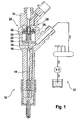
- FIG. 1 a fuel injection valve 10 according to the invention with the fuel-supplying components 12 is shown schematically in longitudinal section.
- the basic mode of operation of such a fuel injection valve 10 is known to the person skilled in the art and will therefore not be explained in detail. More detailed information can be found for example in the cited document and in the application DE 10 2006 027 485 A1 ,
- the fuel injection valve 10 has a valve needle 14, a control chamber 16, which is operatively connected to the valve needle 14, a drain channel 18, which is designed to connect the control chamber 16 with a leakage oil chamber 20, and a control valve 22, which is used to open and close the drain channel 18 is formed.
- the control valve 22 has a guide element 24, also called guide pin on which an actuator 26, also called sealing sleeve or armature, is held axially displaceable, wherein the actuator 26 is acted upon in the direction of a sealing seat 28 with a force.
- the control valve 22 further includes an actuator 29, here an electromagnet, which is adapted to lift the actuator 26 from the sealing seat 28 up-related to the figure.
- the actuator 29 is supported here with its outer region on projections 30 of the holding body 31.
- FIG. 2 is an enlargement of FIG. 1 shown in the region of the control valve 22.
- an intermediate element 32 which forms the sealing seat 28 inter alia in cooperation with the adjusting element 26 .
- the grooves 34, 36 are here executed annularly along the entire circumference of the intermediate element 32.
- a stop member 38 is inserted, which protrudes from the first groove 34 and is designed here as a sickle disc.
- the stop element 38 is displaceable along a longitudinal direction L of the intermediate element 32 by a defined path, which will be shown in more detail below.
- the stop element 38 bears against an end face 40 of the actuating element 26 and interacts with it in such a way that an upper stroke stop (indicated by the line 42) of the actuating element 26 is predetermined.
- a valve spring 44 provides a biasing force that pushes the stop member 38, and upon application of the actuator 26, also the actuator 26, down-relative to the figure.
- the valve spring 44 is supported on its one side 46 on the stop element 38 and on its other side 48 on a holding portion 50 which is formed on the intermediate element 32.
- the holding portion 50 has the second groove 36 and a holding member 52 which is designed as a sickle disc.
- the stop element 38 is secured with a first fixing element 54 and the holding element 52 with a second fixing element 56 in the respective seat.
- the intermediate element 32 has a drainage groove 60 at its first end 58. On the first end 58, an optional adjustment disk 62 for the residual air gap is also shown. Furthermore, a dashed circle 62 is shown, which indicates a region of the control valve 22, which is shown enlarged in the following figure.
- the intermediate element 32 is, as already out FIG. 1 can be seen, with respect to the actuator 29 is not arranged displaced upwards.
- FIG. 3 represents the area enlarged, which was previously indicated by the circle 62. By means of two dashed parallel lines, the path d is shown, by which the spacer 38 in the first groove 34 can shift.
- the valve spring 44 presses the stop element 38 down-related to the figure. Since the end face 40 of the actuating element 26 bears against the stop element 38, the actuating element 26 is also pressed down against the sealing seat 28. If now the actuator 29 is actuated, the actuator 26 is pulled against the force of the valve spring 44 upwards. The stop element 38 now sets the path d back, since the magnetic attraction of the actuator 29 to the actuator 26 is greater than the force of the valve spring 44. After the stop element 38 has been pushed by the actuator 26 by the way d up, it hits the top End of the groove 34 and is mechanically blocked.
- the actuator 26 Since the end face 40 of the actuating element 26 bears against the stop element 38, Also, a further movement of the actuating element 26 is prevented. Thus, the actuator 26 has well defined the upper stroke stop 42 reached. If the actuator 29 is de-energized, eliminates the attraction of the actuator 26, and the valve spring 44 pushes the stop member 38 down and thus the actuator 26 against the sealing seat 28. Since in this way, the lower stroke stop on the sealing seat 28 is well defined, can be determined by the invention, the total stroke of the actuator 26.
- FIG. 4 shows the control valve FIG. 2 with the guide element 24 and the actuator 29, which is designed as an electromagnet and has a magnetic core 64 and a magnetic coil 66.
- the intermediate element 32 is seated on the guide element 24, wherein a spring 68, also called a position spring or contact spring, is arranged between the guide element 24 and the intermediate element 32.
- a spring 68 also called a position spring or contact spring, is arranged between the guide element 24 and the intermediate element 32.
- a residual air gap remains between the actuating element 26 and the actuator 29. This residual air gap can easily be adjusted in the fuel injection valve 10 according to the invention, optionally using the adjusting washer 62 shown.
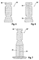
- FIGS. 5, 6 and 7 show embodiments of the intermediate element 32nd FIG. 5 shows the intermediate element 32 FIG. 2
- FIG. 6 shows an intermediate element 32 'with a central drain hole 70, which opens into a transverse bore 72
- FIG. 7 shows an intermediate element 32 ", which is formed integrally with the guide element 24.
- the last-mentioned embodiment can be used in particular for the fact that the magnetic core 64 is supported via the intermediate element 32" in the holding body.
Landscapes
- Engineering & Computer Science (AREA)
- Chemical & Material Sciences (AREA)
- Combustion & Propulsion (AREA)
- Mechanical Engineering (AREA)
- General Engineering & Computer Science (AREA)
- Physics & Mathematics (AREA)
- Fluid Mechanics (AREA)
- Fuel-Injection Apparatus (AREA)
Description
- Die Erfindung betrifft ein Kraftstoffeinspritzventil für Brennkraftmaschinen, insbesondere ein Magnetventil für Common-Rail-Injektoren (CRI), gemäß dem Oberbegriff des Anspruchs 1.
- Aus der europäischen Patentanmeldung
EP 1 612 403 A1 sind Kraftstoffeinspritzventile für schnelllaufende, selbstzündende Brennkraftmaschinen bekannt, die den Kraftstoff direkt in einen Brennraum einer Brennkraftmaschine einspritzen. - Bei Magnetventilen für Common-Rail-Injektoren gemäß dem Stand der Technik ergibt sich konstruktionsbedingt immer ein Einfluss des Raildrucks auf den Hub des Schaltventils beziehungsweise des Steuerventils (Ankerhub). Die Ursache hierfür liegt in elastischen Verformungen, die den Ankerhub beeinflussen und die direkt oder indirekt dem Raildruck unterliegen.
- Bei bestimmten Bauarten von Magnetventilen ist der Einfluss auf den Ankerhub besonders groß. Dazu zählen solche Magnetventile, bei denen der obere Hubanschlag am Magneten ausgebildet ist. Durch den Raildruck tritt die Situation ein, dass der Ventilsitz seine axiale Position gegenüber dem Haltekörper verändert, wohingegen die Position des oberen Hubanschlags unverändert bleibt. Insgesamt bedeutet dies, dass der Ankerhub mit zunehmendem Raildruck abnimmt.
- Voraussetzung für die zuverlässige Funktion des Magnetventils ist, dass der Ankerhub bei allen Raildrücken über einem Minimalwert liegt, also auch beim größten Raildruck der Ankerhub noch den Minimalwert erzielt. Im drucklosen Zustand muss daher ein Ankerhub eingestellt werden, der deutlich oberhalb des Minimalwerts liegt.
- Ein großer Ankerhub führt aber dazu, dass der Anker beziehungsweise das Stellelement bei Betätigung des Elektromagneten über eine längere Strecke beschleunigt wird und somit eine größere kinetische Energie aufbaut. (Der gleiche Effekt tritt auch auf, wenn die Ventilfeder das Stellelement wieder zurück zum Dichtsitz drückt).
- Beim Anschlagen des Stellelements am oberen Hubanschlag (beziehungsweise am Ventilsitz) findet daher ein Stoß statt, der zu einer erheblichen Belastung des Stellelements und in der Regel auch zu einem Prellen des Stellelements führt. Da das Prellen aber negative Auswirkungen auf die Zumessgenauigkeit des Injektors hat, ist ein großer Ankerhub unerwünscht.
- Ein weiterer Aspekt, der bei Kraftstoffeinspritzventilen von Bedeutung ist, betrifft den Zusammenbau. Ein Einspritzventil besteht aus einer Vielzahl von Einzelteilen, die im zusammengebauten Zustand sehr genau zusammenspielen müssen. Dazu zählen insbesondere die Einstellung des Hubs des Stellelements, auch Ankerhub genannt, die Einstellung der Ventilfederkraft und schließlich auch das Sicherstellen eines Minimalabstands zwischen dem Stellelement und dem Aktuator. (Bei einem Magnetventil wird dieser Abstand Restluftspalt genannt).
- Bei Einspritzventilen ist es eine Zielsetzung, den benötigten Bauraum sowie den erforderlichen Montageaufwand so gering wie möglich zu halten. Insbesondere ist es aufwändig und daher unerwünscht, während des Zusammenbaus und/oder nach dem Zusammenbau des Einspritzventils, Einstellungen und/oder Korrekturen vornehmen zu müssen. Daher ist ein Aufbau für ein Einspritzventil wünschenswert, der es auf möglichst einfache Weise erlaubt, die Einstellungen und/oder Korrekturen bereits vor der Endmontage an kleineren Baugruppen vorzunehmen, wenn die einzelnen Teile noch gut zugänglich sind.
- Es sei darauf hingewiesen, dass die zuvor genannten Probleme auch bei Ventilen mit einem piezoelektrischen Aktuator auftreten können. Daher ergeben sich aus Erkenntnissen, die in diesem Zusammenhang für ein Magnetventil aufgefunden werden, auch unmittelbar Möglichkeiten, ein Ventil mit piezoelektrischem Aktuator zu verbessern.
- Aufgabe der Erfindung ist es, ein Kraftstoffeinspritzventil gemäß dem Oberbegriff des Anspruchs 1, insbesondere ein Magnetventil, aufzuzeigen, das bezüglich Aufbau, Einstellung und Montage möglichst einfach ausgestaltet ist und gleichzeitig eine gute Einstellbarkeit der einzustellenden Ventilparameter bietet. Dabei soll insbesondere auch eine Möglichkeit aufgezeigt werden, bei der sich der Ankerhub auch bei hohem Raildruck wenig ändert und insbesondere im Wesentlichen unverändert bleibt.
- Die Aufgabe ist bei einem Kraftstoffeinspritzventil gemäß dem Oberbegriff des Anspruchs 1 dadurch gelöst, dass das Stellelement, das üblicherweise auch als Anker oder als Dichthülse bezeichnet wird, ein zentrales Durchgangsloch aufweist, das einen sich verjüngenden Abschnitt umfasst, in dem eine Verdickung eines Zwischenelements angeordnet ist, wobei der Durchmesser der Verdickung größer als der kleinste Durchmesser des sich verjüngenden Abschnitts des zentralen Durchgangslochs des Stellelements ist, wobei das Zwischenelement ein Anschlagelement aufweist, das nur bis zu einem oberen Anschlag auf dem Zwischenelement axial verschiebbar ist und das bei axialer Verschiebung auf dem Zwischenelement nach unten in Kontakt mit dem Stellelement kommt. Die Begriffe oben und unten werden stets entsprechend der Darstellung der Erfindung in der Zeichnung verwendet. Das zentrale Durchgangsloch ist vorzugsweise als Innenbohrung ausgeführt, die im oberen Bereich verjüngt ist. Das Zwischenelement ist durch die Innenbohrung geführt beziehungsweise gesteckt. Durch die Verdickung wird am Zwischenelement ein unterer Anschlag für das Stellelement ausgebildet. In der tiefstmöglichen axialen Position des Stellelements bezogen auf das Zwischenelement bildet sich zwischen diesen beiden Elementen eine Berührlinie aus. Diese ist vorzugsweise als Dichtsitz gestaltet und dient im fertig montierten Zustand des Ventils zur Abdichtung einer Druckkammer. Durch das Anschlagelement wird das axiale Spiel des Stellelements zwischen seinem überlicherweise als Dichtsitz ausgebildeten unteren Anschlag am Zwischenelement und seinem oberen Anschlag festgelegt. Das genannte axiale Spiel, welches gleich dem Ankerhub des Schaltventils ist, kann folglich durch die Dicke des Anschlagelements eingestellt werden.
- Ein Aspekt der Erfindung ist darin zu sehen, dass die Begrenzung des oberen Hubanschlags, also wenn sich das Stellelement in größtmöglicher Nähe zum Aktuator befindet, nicht mittels eines Elements erfolgt, welches sich unmittelbar zwischen dem Stellelement und dem Aktuator befindet, beispielsweise einer Restluftspaltsscheibe bei einem Magnetventil. Vielmehr wird der Hubanschlag mittels des Zwischenelements realisiert, welches sich am Aktuator oder an anderen Teilen des Einspritzventils abstützt. Es ergibt sich dadurch ein Einspritzventil mit einem einfachen Aufbau, der auch einen einfachen Zusammenbau des Einspritzventils ermöglicht.
- Ein weiterer Aspekt der Erfindung ergibt sich aus der oben genannten Tatsache, dass sowohl der obere als auch der untere Hubanschlag des Stellelements, das auch Anker oder Dichthülse genannt wird, am Zwischenelement ausgebildet beziehungsweise vorgesehen oder angebracht sind und sich nur in kurzer Entfernung voneinander befinden. Dies führt unter anderem dazu, dass sich Änderungen aufgrund des Raildrucks in geringerem Maße oder gar nicht mehr auf den Ankerhub auswirken. Dadurch ist es nicht länger erforderlich, im Ruhezustand einen besonders großen Hub für das Stellelement einzustellen, um die Funktionstüchtigkeit auch bei hohem Raildruck sicherzustellen. Vielmehr kann nun ein kleiner Hub eingestellt werden, der bei steigendem Raildruck im Wesentlichen konstant bleibt.
- Ein bevorzugtes Ausführungsbeispiel des Ventils ist dadurch gekennzeichnet, dass das Anschlagelement an der Stirnfläche des Stellelements anliegt. Dies stellt eine einfache Möglichkeit dar, den oberen Hubanschlag zu definieren und die Kraft, die das Anschlagelement am Ende des definierten Wegs stoppt, in das Stellelement einzuleiten. Insbesondere ist es vorteilhaft, wenn das Anschlagelement die Bewegung des Stellelements mechanisch blockiert, da sich dadurch eine zuverlässige und einfach zu realisierende Ausführung ergibt.
- Ein weiteres bevorzugtes Ausführungsbeispiel des Ventils ist dadurch gekennzeichnet, dass das Zwischenelement mindestens eine erste Nut aufweist, in die das Anschlagelement eingesetzt ist, wobei das Anschlagelement zumindest bereichsweise aus der ersten Nut hervorsteht. Auf diese Weise lässt sich das Anschlagelement kostengünstig und mechanisch robust herstellen. Die Ausdehnung des Anschlagelements in Längsrichtung des Zwischenelements ist dabei geringer als der Abstand zwischen der Auflagefläche für das Anschlagelement am Stellelement und der oberen Stirnfläche der ersten Nut im Zwischenelement, der sich ergibt, wenn das Stellelement sich an seinem unteren Anschlag am Zwischenelement befindet. Somit ergibt sich ein definiertes Spiel des Anschlagelements und damit auch des Stellelements in der Längsrichtung relativ zum Zwischenelement. Dabei ist es insbesondere vorteilhaft, wenn das Anschlagelement als Sichelscheibe ausgeführt ist. So kann das Zwischenelement beispielsweise durch eine Öffnung geführt werden, deren Durchmesser geringer ist als der der Sichelscheibe, und die Sichelscheibe danach aufgesetzt werden. Dies ergibt eine größere konstruktive Freiheit und eine Vereinfachung der Montage.
- Ein weiteres bevorzugtes Ausführungsbeispiel des Ventils ist dadurch gekennzeichnet, dass das Kraftstoffeinspritzventil eine Ventilfeder zur Beaufschlagung des Stellelements in Richtung auf den Dichtsitz aufweist, wobei sich die Ventilfeder an einer Seite am Anschlagelement und an einer anderen Seite an einem Haltebereich abstützt, der am Zwischenelement ausgebildet ist. Grundsätzlich ist es ebenfalls möglich, dass sich die Ventilfeder in bekannter Weise am Stellelement abstützt. Das hier vorgeschlagene Ausführungsbeispiel bietet aber den Vorteil, dass das Anschlagelement in Bezug auf das Stellelement stets eine feste axiale Position aufweist und folglich bei Schaltvorgängen weder taumeln noch zunächst nur punktuell anschlagen kann. In beiden Fällen besteht der Vorteil, dass das Zwischenelement bereits mit Stellelement, Anschlagelement und Haltebereich gefertigt beziehungsweise zusammengesetzt werden kann, bevor es in das Einspritzventil eingesetzt wird. Es steht also schon im frühen Stadium der Montage eine Baugruppe zur Verfügung, bei der der Hub des Stellelements und die Vorspannkraft, die auf das Anschlagelement beziehungsweise das Stellelement wirkt, eingestellt sind. Diese voreingestellte Baugruppe kann dann als Ganzes mit dem Stellelement voraus auf das Führungselement geschoben werden.
- Ein weiteres bevorzugtes Ausführungsbeispiel des Ventils ist dadurch gekennzeichnet, dass der Haltebereich ein Halteelement aufweist, das in eine zweite am Zwischenelement ausgebildete Nut eingelegt ist und zumindest bereichsweise aus der zweiten Nut hervorsteht. Diese Ausgestaltung bietet eine konstruktiv einfache und kostengünstige Lösung. Das Halteelement ist dabei vorzugsweise als Sichelscheibe ausgeführt, und zwar mit den gleichen Vorteilen, wie zum Anschlagelement erläutert.
- Ein weiteres bevorzugtes Ausführungsbeispiel des Ventils ist dadurch gekennzeichnet, dass das Zwischenelement an seinem ersten Ende, das dem Stellelement abgewandt ist, eine Ablaufrille, eine oder mehrere schräg verlaufende Ablaufbohrungen oder eine zentrale, in eine Querbohrung mündende Ablaufbohrung aufweist. Auf diese Weise lässt sich das erforderliche Abströmen des Kraftstoffs aus dem Ankerraum zum Rücklaufanschluss hin realisieren.
- Ein weiteres bevorzugtes Ausführungsbeispiel des Ventils ist dadurch gekennzeichnet, dass das Anschlagelement und/oder das Halteelement mittels eines Fixierelements in ihrem Sitz in der jeweiligen Nut gesichert ist. Dabei umschließt das Fixierelement, insbesondere eine Fixierhülse, bevorzugt das jeweilige Element und stellt so sicher, dass das jeweilige Element radial positioniert bleibt und insbesondere nicht aus der für das jeweilige Element vorgesehenen Nut im Zwischenelement entweichen kann.
- Ein weiteres bevorzugtes Ausführungsbeispiel des Ventils ist dadurch gekennzeichnet, dass sich der Aktuator mit einem äußeren Bereich an einem Haltekörper des Kraftstoffeinspritzventils abstützt. Bei einem Magnetventil findet die Abstützung bevorzugt über den Außenpol statt. Damit entsteht zwischen der oberen Stirnfläche des Führungselements, auch Ankerführung genannt, und der unteren Stirnfläche des Zwischenelements, auch Sitzzapfen genannt, ein Kraftstoffvolumen. Wenn die aus Zwischenelement, Stellelement und Anschlagelement sowie gegebenenfalls aus Haltebereich und Ventilfeder bestehende Baugruppe nicht bereits anderweitig befestigt ist, wird sie, sobald der Raildruck anliegt, nach oben in ihre Sollposition, vorzugsweise gegen einen zum Haltekörper fixierten Anschlag, gedrückt. Ein weiteres bevorzugtes Ausführungsbeispiel des Ventils ist dadurch gekennzeichnet, dass zwischen dem Führungselement und dem Zwischenelement eine Feder angeordnet ist. Dies bewirkt, dass sich das Schaltventil auch im drucklosen Zustand in seiner Sollposition befindet.
- Ein weiteres bevorzugtes Ausführungsbeispiel des Ventils ist dadurch gekennzeichnet, dass das Zwischenelement und das Führungselement einstückig ausgeführt sind. Dies ermöglicht einen stabilen Verbund zwischen dem Aktuator, dem Zwischenelement und dem Führungselement. Insbesondere wenn sich Aktuator und Führungselement an demselben Bezugselement, üblicherweise am Haltekörper des Einspritzventils, abstützen, ist der Verbund wenig empfindlich gegenüber Schwankungen des Raildrucks, die sonst zu Dehnungen und/oder Verschiebungen führen können.
- Weitere Vorteile, Merkmale und Einzelheiten der Erfindung ergeben sich aus der nachfolgenden Beschreibung, in der unter Bezugnahme auf die Zeichnung verschiedene Ausführungsbeispiele im Einzelnen beschrieben sind.
- Es zeigen:
- Figur 1
- einen Längsschnitt durch ein erfindungsgemäßes Kraftstoffeinspritzungsventil mit schematisch dargestellten Zufuhrkomponenten;
- Figur 2
- eine Vergrößerung von
Figur 1 im Bereich des Steuerventils; - Figur 3
- einen vergrößerten Ausschnitt aus der
Figur 2 ; - Figur 4
- das Steuerventil aus
Figur 2 mit einem Führungselement und einem Aktuator; - Figur 5
- ein Zwischenelement aus der
Figur 4 ; - Figur 6
- eine andere Ausführungsform eines Zwischenelements; und
- Figur 7
- eine einstückige Ausgestaltung von Zwischenelement und Führungselement.
- In
Figur 1 ist ein erfindungsgemäßes Kraftstoffeinspritzventil 10 mit den Kraftstoff zuführenden Komponenten 12 schematisch im Längsschnitt dargestellt. Die prinzipielle Funktionsweise eines solchen Kraftstoffeinspritzventils 10 ist dem Fachmann bekannt und wird daher nicht im Detail erläutert. Genauere Informationen hierzu finden sich beispielsweise in der eingangs genannten Druckschrift sowie in der AnmeldungDE 10 2006 027 485 A1 . - Das Kraftstoffeinspritzventil 10 weist eine Ventilnadel 14, einen Steuerraum 16, der mit der Ventilnadel 14 wirkverbunden ist, einen Ablaufkanal 18, der zur Verbindung des Steuerraums 16 mit einem Leckölraum 20 ausgebildet ist, und ein Steuerventil 22 auf, das zum Öffnen und Verschließen des Ablaufkanals 18 ausgebildet ist.
- Das Steuerventil 22 weist ein Führungselement 24 auf, auch Führungszapfen genannt, auf dem ein Stellelement 26, auch Dichthülse oder Anker genannt, axial verlagerbar gehalten ist, wobei das Stellelement 26 in Richtung auf einen Dichtsitz 28 mit einer Kraft beaufschlagt ist. Das Steuerventil 22 weist ferner einen Aktuator 29 auf, hier ein Elektromagnet, der dafür ausgebildet ist, das Stellelement 26 von dem Dichtsitz 28 nach oben -bezogen auf die Figur- abzuheben. Der Aktuator 29 stützt sich hier mit seinem äußeren Bereich auf Vorsprüngen 30 des Haltekörpers 31 ab.
- In
Figur 2 ist eine Vergrößerung vonFigur 1 im Bereich des Steuerventils 22 dargestellt. In ein Zwischenelement 32, das unter anderem im Zusammenspiel mit dem Stellelement 26 den Dichtsitz 28 ausbildet, ist eine erste Nut 34 und eine zweite Nut 36 eingebracht. Die Nuten 34, 36 sind hier ringförmig entlang des gesamten Umfangs des Zwischenelements 32 ausgeführt. In die erste Nut 34 ist ein Anschlagelement 38 eingesetzt, welches aus der ersten Nut 34 hervorsteht und hier als Sichelscheibe ausgeführt ist. Das Anschlagelement 38 ist entlang einer Längsrichtung L des Zwischenelements 32 um einen definierten Weg verlagerbar, der nachfolgend noch genauer gezeigt wird. Das Anschlagelement 38 liegt an einer Stirnfläche 40 des Stellelements 26 an und wirkt mit ihm in der Art zusammen, dass ein oberer Hubanschlag (mit der Linie 42 angedeutet) des Stellelements 26 vorgegeben ist. - Eine Ventilfeder 44 stellt eine Vorspannkraft bereit, die das Anschlagelement 38, und bei Anliegen des Stellelements 26 auch das Stellelement 26, nach unten -bezogen auf die Figurdrückt. Dafür stützt sich die Ventilfeder 44 an ihrer einen Seite 46 am Anschlagelement 38 ab und an ihrer anderen Seite 48 an einem Haltebereich 50, der am Zwischenelement 32 ausgebildet ist. Der Haltebereich 50 weist die zweite Nut 36 und ein Halteelement 52 auf, das als Sichelscheibe ausgeführt ist.
- Das Anschlagelement 38 ist mit einem ersten Fixierelement 54 und das Halteelement 52 mit einem zweiten Fixierelement 56 im jeweiligen Sitz gesichert.
- Das Zwischenelement 32 weist an seinem ersten Ende 58 eine Ablaufrille 60 auf. Auf dem ersten Ende 58 ist zudem eine optionale Einstellscheibe 62 für den Restluftspalt gezeigt. Ferner ist ein gestrichelter Kreis 62 dargestellt, der einen Bereich des Steuerventils 22 andeutet, der in der nachfolgenden Figur vergrößert dargestellt wird. Das Zwischenelement 32 ist, wie bereits aus
Figur 1 ersichtlich ist, gegenüber dem Aktuator 29 nicht nach oben verschiebbar angeordnet. -
Figur 3 stellt den Bereich vergrößert dar, der vorher mit dem Kreis 62 angedeutet wurde. Mittels zweier gestrichelter paralleler Linien ist der Weg d dargestellt, um den sich das Abstandselement 38 in der ersten Nut 34 verlagern kann. Im Hinblick auf die bisherigen Erläuterungen soll nun die Funktionsweise des vorgestellten Steuerventils 22 näher beschrieben werden. - Im Ruhezustand, also wenn der Aktuator 29, hier ein Elektromagnet, nicht betätigt wird, drückt die Ventilfeder 44 das Anschlagelement 38 nach unten -bezogen auf die Figur. Da die Stirnfläche 40 des Stellelements 26 am Anschlagelement 38 anliegt, wird auch das Stellelement 26 nach unten, und zwar gegen den Dichtsitz 28, gedrückt. Wird nun der Aktuator 29 betätigt, wird das Stellelement 26 gegen die Kraft der Ventilfeder 44 nach oben gezogen. Das Anschlagelement 38 legt nun den Weg d zurück, da die magnetische Anziehungskraft des Aktuators 29 auf das Stellelement 26 größer ist als die Kraft der Ventilfeder 44. Nachdem das Anschlagelement 38 vom Stellelement 26 um den Weg d nach oben geschoben wurde, stößt es am oberen Ende der Nut 34 an und wird so mechanisch blockiert. Da die Stirnfläche 40 des Stellelements 26 am Anschlagelement 38 anliegt, wird auch eine weitere Bewegung des Stellelements 26 unterbunden. Damit hat das Stellelement 26 wohldefiniert den oberen Hubanschlag 42 erreicht. Wird der Aktuator 29 stromlos geschaltet, entfällt die Anziehungskraft auf das Stellelement 26, und die Ventilfeder 44 drückt das Anschlagelement 38 nach unten und damit das Stellelement 26 gegen den Dichtsitz 28. Da auf diese Weise auch der untere Hubanschlag am Dichtsitz 28 wohldefiniert ist, kann durch die Erfindung der Hub des Stellelements 26 insgesamt festgelegt werden.
-
Figur 4 zeigt das Steuerventil ausFigur 2 mit dem Führungselement 24 und dem Aktuator 29, der als Elektromagnet ausgeführt ist und einen Magnetkern 64 sowie eine Magnetspule 66 aufweist. Das Zwischenelement 32 sitzt auf dem Führungselement 24, wobei eine Feder 68, auch Positionsfeder oder Kontaktfeder genannt, zwischen dem Führungselement 24 und dem Zwischenelement 32 angeordnet ist. Wie anhand des eingezeichneten oberen Hubanschlags 42 zu erkennen ist, verbleibt ein Restluftspalt zwischen dem Stellelement 26 und dem Aktuator 29. Dieser Restluftspalt lässt sich bei dem erfindungsgemäßen Kraftstoffeinspritzventil 10 leicht einstellen, optional unter Verwendung der gezeigten Einstellscheibe 62. -
Figuren 5, 6 und 7 zeigen Ausgestaltungen des Zwischenelements 32.Figur 5 zeigt das Zwischenelement 32 ausFigur 2 .Figur 6 zeigt ein Zwischenelement 32' mit einer zentralen Ablaufbohrung 70, die in eine Querbohrung 72 mündet.Figur 7 zeigt ein Zwischenelement 32", das einstückig mit dem Führungselement 24 ausgebildet ist. Die letztgenannte Ausgestaltung kann insbesondere dafür verwendet werden, dass sich der Magnetkern 64 über das Zwischenelement 32" im Haltekörper abstützt.
Claims (10)
- Kraftstoffeinspritzventil (10) für Brennkraftmaschinen, mit einer Ventilnadel (14), die durch ihre Längsbewegung die Öffnung wenigstens einer Einspritzöffnung steuert, mit einem Steuerraum (16), dessen Druck wenigstens mittelbar auf die Ventilnadel (14) wirkt und der durch einen Ablaufkanal (18), mit einem Leckölraum (20) verbindbar ist, und mit einem Steuerventil (22), das zum Öffnen und Verschließen des Ablaufkanals (18) ausgebildet ist, wobei das Steuerventil (22) ein auf einem Führungselement (24) verlagerbar gehaltenes Stellelement (26) aufweist, das in Richtung auf einen Dichtsitz (28) mit einer Kraft beaufschlagt ist, und mit einem Aktuator (30) zum Abheben des Stellelements (26) von dem Dichtsitz (28), dadurch gekennzeichnet, dass das Stellelement (26) ein zentrales Durchgangsloch aufweist, das einen sich verjüngenden Abschnitt umfasst, in dem eine Verdickung eines Zwischenelements (32) angeordnet ist, wobei der Durchmesser der Verdickung größer als der kleinste Durchmesser des sich verjüngenden Abschnitts des zentralen Durchgangslochs des Stellelements (26) ist, wobei das Zwischenelement (32) ein Anschlagelement (38) aufweist, das nur bis zu einem oberen Anschlag auf dem Zwischenelement (32) axial verschiebbar ist und das bei axialer Verschiebung auf dem Zwischenelement nach unten in Kontakt mit dem Stellelement (26) kommt.
- Kraftstoffeinspritzventil nach Anspruch 1, dadurch gekennzeichnet, dass das Anschlagelement (38) an der Stirnfläche (40) des Stellelements (26) anliegt.
- Kraftstoffeinspritzventil nach Anspruch 1 oder 2, dadurch gekennzeichnet, dass das Zwischenelement (32) mindestens eine erste Nut (34) aufweist, in die das Anschlagelement (38) eingesetzt ist, wobei das Anschlagelement (38) zumindest bereichsweise aus der ersten Nut (34) hervorsteht.
- Kraftstoffeinspritzventil nach einem der Ansprüche 1 bis 3, gekennzeichnet durch eine Ventilfeder (44) zur Beaufschlagung des Stellelements (26) in Richtung auf den Dichtsitz (28), wobei sich die Ventilfeder (44) an einer Seite (46) am Anschlagelement (38) oder am Stellelement (26) und an einer anderen Seite (48) an einem Haltebereich abstützt (50), der am Zwischenelement (32) ausgebildet ist.
- Kraftstoffeinspritzventil nach Anspruch 4, dadurch gekennzeichnet, dass der Haltebereich (50) ein Halteelement (52) aufweist, das in eine zweite am Zwischenelement (32) ausgebildete Nut (36) eingelegt ist und zumindest bereichsweise aus der zweiten Nut (36) hervorsteht.
- Kraftstoffeinspritzventil nach einem der Ansprüche 1 bis 5, dadurch gekennzeichnet, dass das Zwischenelement (32) an seinem ersten Ende (58), das dem Stellelement (26) abgewandt ist, eine Ablaufrille (60) aufweist oder eine zentrale Ablaufbohrung (70) aufweist, die in einer Querbohrung (72) mündet, oder eine oder mehrere schräg verlaufende Ablaufbohrungen aufweist.
- Kraftstoffeinspritzventil nach einem der Ansprüche 1 bis 6, dadurch gekennzeichnet, dass das Anschlagelement (38) und/oder das Halteelement (52) mittels eines Fixierelements (54,56) in ihrem/seinem Sitz in der jeweiligen Nut (34,36) gesichert sind/ist.
- Kraftstoffeinspritzventil nach einem der Ansprüche 1 bis 7, dadurch gekennzeichnet, dass sich der Aktuator (29) mit einem äußeren Bereich an einem Haltekörper (31) des Kraftstoffeinspritzventils (10) abstützt.
- Kraftstoffeinspritzventil nach einem der Ansprüche 1 bis 8, dadurch gekennzeichnet, dass zwischen dem Führungselement (24) und dem Zwischenelement (32) eine Feder (68) angeordnet ist.
- Kraftstoffeinspritzventil nach einem der Ansprüche 1 bis 9, dadurch gekennzeichnet, dass das Zwischenelement (32) und das Führungselement (24) einstückig ausgeführt sind.
Applications Claiming Priority (2)
| Application Number | Priority Date | Filing Date | Title |
|---|---|---|---|
| DE102007037824A DE102007037824A1 (de) | 2007-08-10 | 2007-08-10 | Kraftstoffeinspritzventil für Brennkraftmaschinen |
| PCT/EP2008/058902 WO2009021785A1 (de) | 2007-08-10 | 2008-07-09 | Kraftstoffeinspritzventil für brennkraftmaschinen |
Publications (2)
| Publication Number | Publication Date |
|---|---|
| EP2185808A1 EP2185808A1 (de) | 2010-05-19 |
| EP2185808B1 true EP2185808B1 (de) | 2012-01-25 |
Family
ID=39797944
Family Applications (1)
| Application Number | Title | Priority Date | Filing Date |
|---|---|---|---|
| EP08774908A Not-in-force EP2185808B1 (de) | 2007-08-10 | 2008-07-09 | Kraftstoffeinspritzventil für brennkraftmaschinen |
Country Status (4)
| Country | Link |
|---|---|
| EP (1) | EP2185808B1 (de) |
| AT (1) | ATE542995T1 (de) |
| DE (1) | DE102007037824A1 (de) |
| WO (1) | WO2009021785A1 (de) |
Families Citing this family (1)
| Publication number | Priority date | Publication date | Assignee | Title |
|---|---|---|---|---|
| DE102009046563A1 (de) * | 2009-11-10 | 2011-05-12 | Robert Bosch Gmbh | Kraftstoffinjektor |
Family Cites Families (4)
| Publication number | Priority date | Publication date | Assignee | Title |
|---|---|---|---|---|
| DE10100422A1 (de) * | 2001-01-08 | 2002-07-11 | Bosch Gmbh Robert | Magnetventil zur Steuerung eines Einspritzventils einer Brennkraftmaschine |
| DE602004004254T2 (de) | 2004-06-30 | 2007-07-12 | C.R.F. S.C.P.A. | Servoventil zum Steuern eines Einspritzventils einer Brennkraftmaschine |
| DE102004050992A1 (de) * | 2004-10-20 | 2006-04-27 | Robert Bosch Gmbh | Magnetventilbetätigter Kraftstoffinjektor mit hydraulischem Überhubanschlag |
| DE102006027485A1 (de) | 2006-06-14 | 2007-12-20 | Robert Bosch Gmbh | Kraftstoffeinspritzventil mit Sicherheitssteuerventil |
-
2007
- 2007-08-10 DE DE102007037824A patent/DE102007037824A1/de not_active Withdrawn
-
2008
- 2008-07-09 AT AT08774908T patent/ATE542995T1/de active
- 2008-07-09 EP EP08774908A patent/EP2185808B1/de not_active Not-in-force
- 2008-07-09 WO PCT/EP2008/058902 patent/WO2009021785A1/de active Application Filing
Also Published As
| Publication number | Publication date |
|---|---|
| WO2009021785A1 (de) | 2009-02-19 |
| EP2185808A1 (de) | 2010-05-19 |
| DE102007037824A1 (de) | 2009-02-12 |
| ATE542995T1 (de) | 2012-02-15 |
Similar Documents
| Publication | Publication Date | Title |
|---|---|---|
| EP1431567B1 (de) | Brennstoffeinspritzventil für Verbrennungskraftmaschinen | |
| EP2307776B1 (de) | Luftspaltbegrenzung bei magnetventil | |
| EP2307697B1 (de) | Kraftstoffinjektor mit zweiteiligem magnetanker | |
| EP2016277B1 (de) | Magnetventil mit stoffschlüssiger ankerverbindung | |
| EP2454467B1 (de) | Ventilanordnung | |
| EP2025922B1 (de) | Kraftstoffeinspritzventil für Brennkraftmaschinen | |
| DE102009045728A1 (de) | Magnetventil sowie Kraftstoff-Injektor mit einem Magnetventil | |
| EP2185808B1 (de) | Kraftstoffeinspritzventil für brennkraftmaschinen | |
| DE102012201413A1 (de) | Magnetventil für einen Kraftstoffinjektor | |
| DE102008040068B4 (de) | Konkave Luftspaltbegrenzung bei Magnetventil | |
| DE102008000695A1 (de) | Anschlagdämpfung | |
| EP2541036A1 (de) | Schaltventil, Verfahren zum Herstellen eines Schaltventils und Kraftstoffinjektor mit einem Schaltventil | |
| EP2156044B1 (de) | Injektor mit druckausgeglichenem steuerventil | |
| EP2314860A1 (de) | Kraftstoff-Injektor | |
| DE102009026564A1 (de) | Kraftstoff-Injektor mit druckausgeglichenem Steuerventil | |
| DE19938921B4 (de) | Einspritzventil für eine Verbrennungskraftmaschine | |
| DE102008000697A1 (de) | Schaltventil für Injektoren | |
| WO2019154687A1 (de) | Elektromagnetisch betätigbares steuerventil für einen kraftstoffinjektor und kraftstoffinjektor | |
| DE102008040161A1 (de) | Magnetventil für einen Kraftstoff-Injektor sowie Kraftstoff-Injektor | |
| WO2009138279A1 (de) | Magnetventil mit ankerschlitzung | |
| DE102016201539A1 (de) | Kraftstoffinjektor | |
| DE102004048604A1 (de) | Ventil für insbesondere gasförmige Medien | |
| DE102008040074A1 (de) | Magnetventil zur Steuerung eines Einspritzventils eines Kraftstoff-Injektors | |
| EP2016276B1 (de) | Kraftstoffinjektor mit optimiertem rücklauf | |
| DE102009029231A1 (de) | Kraftstoffinjektor |
Legal Events
| Date | Code | Title | Description |
|---|---|---|---|
| PUAI | Public reference made under article 153(3) epc to a published international application that has entered the european phase |
Free format text: ORIGINAL CODE: 0009012 |
|
| 17P | Request for examination filed |
Effective date: 20100310 |
|
| AK | Designated contracting states |
Kind code of ref document: A1 Designated state(s): AT BE BG CH CY CZ DE DK EE ES FI FR GB GR HR HU IE IS IT LI LT LU LV MC MT NL NO PL PT RO SE SI SK TR |
|
| AX | Request for extension of the european patent |
Extension state: AL BA MK RS |
|
| 17Q | First examination report despatched |
Effective date: 20100709 |
|
| DAX | Request for extension of the european patent (deleted) | ||
| GRAP | Despatch of communication of intention to grant a patent |
Free format text: ORIGINAL CODE: EPIDOSNIGR1 |
|
| GRAS | Grant fee paid |
Free format text: ORIGINAL CODE: EPIDOSNIGR3 |
|
| GRAA | (expected) grant |
Free format text: ORIGINAL CODE: 0009210 |
|
| AK | Designated contracting states |
Kind code of ref document: B1 Designated state(s): AT BE BG CH CY CZ DE DK EE ES FI FR GB GR HR HU IE IS IT LI LT LU LV MC MT NL NO PL PT RO SE SI SK TR |
|
| REG | Reference to a national code |
Ref country code: GB Ref legal event code: FG4D Free format text: NOT ENGLISH |
|
| REG | Reference to a national code |
Ref country code: CH Ref legal event code: EP |
|
| REG | Reference to a national code |
Ref country code: AT Ref legal event code: REF Ref document number: 542995 Country of ref document: AT Kind code of ref document: T Effective date: 20120215 |
|
| REG | Reference to a national code |
Ref country code: IE Ref legal event code: FG4D |
|
| REG | Reference to a national code |
Ref country code: DE Ref legal event code: R096 Ref document number: 502008006199 Country of ref document: DE Effective date: 20120322 |
|
| REG | Reference to a national code |
Ref country code: NL Ref legal event code: VDEP Effective date: 20120125 |
|
| LTIE | Lt: invalidation of european patent or patent extension |
Effective date: 20120125 |
|
| PG25 | Lapsed in a contracting state [announced via postgrant information from national office to epo] |
Ref country code: HR Free format text: LAPSE BECAUSE OF FAILURE TO SUBMIT A TRANSLATION OF THE DESCRIPTION OR TO PAY THE FEE WITHIN THE PRESCRIBED TIME-LIMIT Effective date: 20120125 Ref country code: LT Free format text: LAPSE BECAUSE OF FAILURE TO SUBMIT A TRANSLATION OF THE DESCRIPTION OR TO PAY THE FEE WITHIN THE PRESCRIBED TIME-LIMIT Effective date: 20120125 Ref country code: IS Free format text: LAPSE BECAUSE OF FAILURE TO SUBMIT A TRANSLATION OF THE DESCRIPTION OR TO PAY THE FEE WITHIN THE PRESCRIBED TIME-LIMIT Effective date: 20120525 Ref country code: NO Free format text: LAPSE BECAUSE OF FAILURE TO SUBMIT A TRANSLATION OF THE DESCRIPTION OR TO PAY THE FEE WITHIN THE PRESCRIBED TIME-LIMIT Effective date: 20120425 Ref country code: NL Free format text: LAPSE BECAUSE OF FAILURE TO SUBMIT A TRANSLATION OF THE DESCRIPTION OR TO PAY THE FEE WITHIN THE PRESCRIBED TIME-LIMIT Effective date: 20120125 Ref country code: BG Free format text: LAPSE BECAUSE OF FAILURE TO SUBMIT A TRANSLATION OF THE DESCRIPTION OR TO PAY THE FEE WITHIN THE PRESCRIBED TIME-LIMIT Effective date: 20120425 |
|
| REG | Reference to a national code |
Ref country code: IE Ref legal event code: FD4D |
|
| PG25 | Lapsed in a contracting state [announced via postgrant information from national office to epo] |
Ref country code: PT Free format text: LAPSE BECAUSE OF FAILURE TO SUBMIT A TRANSLATION OF THE DESCRIPTION OR TO PAY THE FEE WITHIN THE PRESCRIBED TIME-LIMIT Effective date: 20120525 Ref country code: PL Free format text: LAPSE BECAUSE OF FAILURE TO SUBMIT A TRANSLATION OF THE DESCRIPTION OR TO PAY THE FEE WITHIN THE PRESCRIBED TIME-LIMIT Effective date: 20120125 Ref country code: GR Free format text: LAPSE BECAUSE OF FAILURE TO SUBMIT A TRANSLATION OF THE DESCRIPTION OR TO PAY THE FEE WITHIN THE PRESCRIBED TIME-LIMIT Effective date: 20120426 Ref country code: LV Free format text: LAPSE BECAUSE OF FAILURE TO SUBMIT A TRANSLATION OF THE DESCRIPTION OR TO PAY THE FEE WITHIN THE PRESCRIBED TIME-LIMIT Effective date: 20120125 Ref country code: FI Free format text: LAPSE BECAUSE OF FAILURE TO SUBMIT A TRANSLATION OF THE DESCRIPTION OR TO PAY THE FEE WITHIN THE PRESCRIBED TIME-LIMIT Effective date: 20120125 |
|
| PG25 | Lapsed in a contracting state [announced via postgrant information from national office to epo] |
Ref country code: CY Free format text: LAPSE BECAUSE OF FAILURE TO SUBMIT A TRANSLATION OF THE DESCRIPTION OR TO PAY THE FEE WITHIN THE PRESCRIBED TIME-LIMIT Effective date: 20120125 |
|
| PG25 | Lapsed in a contracting state [announced via postgrant information from national office to epo] |
Ref country code: DK Free format text: LAPSE BECAUSE OF FAILURE TO SUBMIT A TRANSLATION OF THE DESCRIPTION OR TO PAY THE FEE WITHIN THE PRESCRIBED TIME-LIMIT Effective date: 20120125 Ref country code: IE Free format text: LAPSE BECAUSE OF FAILURE TO SUBMIT A TRANSLATION OF THE DESCRIPTION OR TO PAY THE FEE WITHIN THE PRESCRIBED TIME-LIMIT Effective date: 20120125 Ref country code: SE Free format text: LAPSE BECAUSE OF FAILURE TO SUBMIT A TRANSLATION OF THE DESCRIPTION OR TO PAY THE FEE WITHIN THE PRESCRIBED TIME-LIMIT Effective date: 20120125 Ref country code: SI Free format text: LAPSE BECAUSE OF FAILURE TO SUBMIT A TRANSLATION OF THE DESCRIPTION OR TO PAY THE FEE WITHIN THE PRESCRIBED TIME-LIMIT Effective date: 20120125 Ref country code: CZ Free format text: LAPSE BECAUSE OF FAILURE TO SUBMIT A TRANSLATION OF THE DESCRIPTION OR TO PAY THE FEE WITHIN THE PRESCRIBED TIME-LIMIT Effective date: 20120125 Ref country code: EE Free format text: LAPSE BECAUSE OF FAILURE TO SUBMIT A TRANSLATION OF THE DESCRIPTION OR TO PAY THE FEE WITHIN THE PRESCRIBED TIME-LIMIT Effective date: 20120125 Ref country code: RO Free format text: LAPSE BECAUSE OF FAILURE TO SUBMIT A TRANSLATION OF THE DESCRIPTION OR TO PAY THE FEE WITHIN THE PRESCRIBED TIME-LIMIT Effective date: 20120125 |
|
| PG25 | Lapsed in a contracting state [announced via postgrant information from national office to epo] |
Ref country code: SK Free format text: LAPSE BECAUSE OF FAILURE TO SUBMIT A TRANSLATION OF THE DESCRIPTION OR TO PAY THE FEE WITHIN THE PRESCRIBED TIME-LIMIT Effective date: 20120125 |
|
| PLBE | No opposition filed within time limit |
Free format text: ORIGINAL CODE: 0009261 |
|
| STAA | Information on the status of an ep patent application or granted ep patent |
Free format text: STATUS: NO OPPOSITION FILED WITHIN TIME LIMIT |
|
| 26N | No opposition filed |
Effective date: 20121026 |
|
| BERE | Be: lapsed |
Owner name: ROBERT BOSCH G.M.B.H. Effective date: 20120731 |
|
| REG | Reference to a national code |
Ref country code: DE Ref legal event code: R097 Ref document number: 502008006199 Country of ref document: DE Effective date: 20121026 |
|
| PG25 | Lapsed in a contracting state [announced via postgrant information from national office to epo] |
Ref country code: MC Free format text: LAPSE BECAUSE OF NON-PAYMENT OF DUE FEES Effective date: 20120731 |
|
| REG | Reference to a national code |
Ref country code: CH Ref legal event code: PL |
|
| GBPC | Gb: european patent ceased through non-payment of renewal fee |
Effective date: 20120709 |
|
| PG25 | Lapsed in a contracting state [announced via postgrant information from national office to epo] |
Ref country code: CH Free format text: LAPSE BECAUSE OF NON-PAYMENT OF DUE FEES Effective date: 20120731 Ref country code: LI Free format text: LAPSE BECAUSE OF NON-PAYMENT OF DUE FEES Effective date: 20120731 Ref country code: ES Free format text: LAPSE BECAUSE OF FAILURE TO SUBMIT A TRANSLATION OF THE DESCRIPTION OR TO PAY THE FEE WITHIN THE PRESCRIBED TIME-LIMIT Effective date: 20120506 Ref country code: GB Free format text: LAPSE BECAUSE OF NON-PAYMENT OF DUE FEES Effective date: 20120709 |
|
| PG25 | Lapsed in a contracting state [announced via postgrant information from national office to epo] |
Ref country code: BE Free format text: LAPSE BECAUSE OF NON-PAYMENT OF DUE FEES Effective date: 20120731 |
|
| PG25 | Lapsed in a contracting state [announced via postgrant information from national office to epo] |
Ref country code: MT Free format text: LAPSE BECAUSE OF FAILURE TO SUBMIT A TRANSLATION OF THE DESCRIPTION OR TO PAY THE FEE WITHIN THE PRESCRIBED TIME-LIMIT Effective date: 20120125 |
|
| PG25 | Lapsed in a contracting state [announced via postgrant information from national office to epo] |
Ref country code: TR Free format text: LAPSE BECAUSE OF FAILURE TO SUBMIT A TRANSLATION OF THE DESCRIPTION OR TO PAY THE FEE WITHIN THE PRESCRIBED TIME-LIMIT Effective date: 20120125 |
|
| PG25 | Lapsed in a contracting state [announced via postgrant information from national office to epo] |
Ref country code: LU Free format text: LAPSE BECAUSE OF NON-PAYMENT OF DUE FEES Effective date: 20120709 |
|
| PG25 | Lapsed in a contracting state [announced via postgrant information from national office to epo] |
Ref country code: HU Free format text: LAPSE BECAUSE OF FAILURE TO SUBMIT A TRANSLATION OF THE DESCRIPTION OR TO PAY THE FEE WITHIN THE PRESCRIBED TIME-LIMIT Effective date: 20080709 |
|
| REG | Reference to a national code |
Ref country code: AT Ref legal event code: MM01 Ref document number: 542995 Country of ref document: AT Kind code of ref document: T Effective date: 20130709 |
|
| PG25 | Lapsed in a contracting state [announced via postgrant information from national office to epo] |
Ref country code: AT Free format text: LAPSE BECAUSE OF NON-PAYMENT OF DUE FEES Effective date: 20130709 |
|
| REG | Reference to a national code |
Ref country code: FR Ref legal event code: PLFP Year of fee payment: 9 |
|
| REG | Reference to a national code |
Ref country code: FR Ref legal event code: PLFP Year of fee payment: 10 |
|
| REG | Reference to a national code |
Ref country code: FR Ref legal event code: PLFP Year of fee payment: 11 |
|
| PGFP | Annual fee paid to national office [announced via postgrant information from national office to epo] |
Ref country code: DE Payment date: 20190924 Year of fee payment: 12 Ref country code: FR Payment date: 20190724 Year of fee payment: 12 Ref country code: IT Payment date: 20190723 Year of fee payment: 12 |
|
| REG | Reference to a national code |
Ref country code: DE Ref legal event code: R119 Ref document number: 502008006199 Country of ref document: DE |
|
| PG25 | Lapsed in a contracting state [announced via postgrant information from national office to epo] |
Ref country code: FR Free format text: LAPSE BECAUSE OF NON-PAYMENT OF DUE FEES Effective date: 20200731 |
|
| PG25 | Lapsed in a contracting state [announced via postgrant information from national office to epo] |
Ref country code: DE Free format text: LAPSE BECAUSE OF NON-PAYMENT OF DUE FEES Effective date: 20210202 |
|
| PG25 | Lapsed in a contracting state [announced via postgrant information from national office to epo] |
Ref country code: IT Free format text: LAPSE BECAUSE OF NON-PAYMENT OF DUE FEES Effective date: 20200709 |