EP1207981B1 - Spindle assembly for force controlled polishing - Google Patents
Spindle assembly for force controlled polishing Download PDFInfo
- Publication number
- EP1207981B1 EP1207981B1 EP00955424A EP00955424A EP1207981B1 EP 1207981 B1 EP1207981 B1 EP 1207981B1 EP 00955424 A EP00955424 A EP 00955424A EP 00955424 A EP00955424 A EP 00955424A EP 1207981 B1 EP1207981 B1 EP 1207981B1
- Authority
- EP
- European Patent Office
- Prior art keywords
- spindle
- feedback loop
- producing device
- force
- force producing
- Prior art date
- Legal status (The legal status is an assumption and is not a legal conclusion. Google has not performed a legal analysis and makes no representation as to the accuracy of the status listed.)
- Expired - Lifetime
Links
- 230000020347 spindle assembly Effects 0.000 title claims description 36
- 238000005498 polishing Methods 0.000 title description 19
- 239000004065 semiconductor Substances 0.000 claims description 14
- 238000000034 method Methods 0.000 claims description 11
- 238000012545 processing Methods 0.000 claims description 10
- 238000004891 communication Methods 0.000 claims description 8
- 238000012544 monitoring process Methods 0.000 claims description 5
- 235000012431 wafers Nutrition 0.000 description 28
- XLYOFNOQVPJJNP-UHFFFAOYSA-N water Substances O XLYOFNOQVPJJNP-UHFFFAOYSA-N 0.000 description 4
- 230000008901 benefit Effects 0.000 description 3
- 230000007246 mechanism Effects 0.000 description 3
- 230000004044 response Effects 0.000 description 3
- 239000000126 substance Substances 0.000 description 3
- RTZKZFJDLAIYFH-UHFFFAOYSA-N Diethyl ether Chemical compound CCOCC RTZKZFJDLAIYFH-UHFFFAOYSA-N 0.000 description 2
- 230000000694 effects Effects 0.000 description 2
- 238000005259 measurement Methods 0.000 description 2
- 238000011160 research Methods 0.000 description 2
- 238000005070 sampling Methods 0.000 description 2
- 240000005020 Acaciella glauca Species 0.000 description 1
- 238000013459 approach Methods 0.000 description 1
- 230000008859 change Effects 0.000 description 1
- 239000003795 chemical substances by application Substances 0.000 description 1
- 238000001816 cooling Methods 0.000 description 1
- 230000005672 electromagnetic field Effects 0.000 description 1
- 239000012530 fluid Substances 0.000 description 1
- 230000006870 function Effects 0.000 description 1
- 239000011521 glass Substances 0.000 description 1
- 238000012886 linear function Methods 0.000 description 1
- 230000008569 process Effects 0.000 description 1
- 235000003499 redwood Nutrition 0.000 description 1
- 238000005096 rolling process Methods 0.000 description 1
- 230000035945 sensitivity Effects 0.000 description 1
- 239000002002 slurry Substances 0.000 description 1
- 239000000758 substrate Substances 0.000 description 1
- 230000001960 triggered effect Effects 0.000 description 1
- 238000004804 winding Methods 0.000 description 1
Images

Classifications
-
- H—ELECTRICITY
- H01—ELECTRIC ELEMENTS
- H01L—SEMICONDUCTOR DEVICES NOT COVERED BY CLASS H10
- H01L21/00—Processes or apparatus adapted for the manufacture or treatment of semiconductor or solid state devices or of parts thereof
- H01L21/02—Manufacture or treatment of semiconductor devices or of parts thereof
- H01L21/04—Manufacture or treatment of semiconductor devices or of parts thereof the devices having potential barriers, e.g. a PN junction, depletion layer or carrier concentration layer
- H01L21/18—Manufacture or treatment of semiconductor devices or of parts thereof the devices having potential barriers, e.g. a PN junction, depletion layer or carrier concentration layer the devices having semiconductor bodies comprising elements of Group IV of the Periodic Table or AIIIBV compounds with or without impurities, e.g. doping materials
- H01L21/30—Treatment of semiconductor bodies using processes or apparatus not provided for in groups H01L21/20 - H01L21/26
- H01L21/302—Treatment of semiconductor bodies using processes or apparatus not provided for in groups H01L21/20 - H01L21/26 to change their surface-physical characteristics or shape, e.g. etching, polishing, cutting
- H01L21/304—Mechanical treatment, e.g. grinding, polishing, cutting
-
- B—PERFORMING OPERATIONS; TRANSPORTING
- B24—GRINDING; POLISHING
- B24B—MACHINES, DEVICES, OR PROCESSES FOR GRINDING OR POLISHING; DRESSING OR CONDITIONING OF ABRADING SURFACES; FEEDING OF GRINDING, POLISHING, OR LAPPING AGENTS
- B24B37/00—Lapping machines or devices; Accessories
- B24B37/005—Control means for lapping machines or devices
-
- B—PERFORMING OPERATIONS; TRANSPORTING
- B24—GRINDING; POLISHING
- B24B—MACHINES, DEVICES, OR PROCESSES FOR GRINDING OR POLISHING; DRESSING OR CONDITIONING OF ABRADING SURFACES; FEEDING OF GRINDING, POLISHING, OR LAPPING AGENTS
- B24B41/00—Component parts such as frames, beds, carriages, headstocks
- B24B41/04—Headstocks; Working-spindles; Features relating thereto
- B24B41/044—Grinding spindles with magnetic or electromagnetic bearings; Features related thereto
-
- B—PERFORMING OPERATIONS; TRANSPORTING
- B24—GRINDING; POLISHING
- B24B—MACHINES, DEVICES, OR PROCESSES FOR GRINDING OR POLISHING; DRESSING OR CONDITIONING OF ABRADING SURFACES; FEEDING OF GRINDING, POLISHING, OR LAPPING AGENTS
- B24B49/00—Measuring or gauging equipment for controlling the feed movement of the grinding tool or work; Arrangements of indicating or measuring equipment, e.g. for indicating the start of the grinding operation
- B24B49/16—Measuring or gauging equipment for controlling the feed movement of the grinding tool or work; Arrangements of indicating or measuring equipment, e.g. for indicating the start of the grinding operation taking regard of the load
-
- G—PHYSICS
- G05—CONTROLLING; REGULATING
- G05B—CONTROL OR REGULATING SYSTEMS IN GENERAL; FUNCTIONAL ELEMENTS OF SUCH SYSTEMS; MONITORING OR TESTING ARRANGEMENTS FOR SUCH SYSTEMS OR ELEMENTS
- G05B19/00—Programme-control systems
- G05B19/02—Programme-control systems electric
- G05B19/18—Numerical control [NC], i.e. automatically operating machines, in particular machine tools, e.g. in a manufacturing environment, so as to execute positioning, movement or co-ordinated operations by means of programme data in numerical form
- G05B19/19—Numerical control [NC], i.e. automatically operating machines, in particular machine tools, e.g. in a manufacturing environment, so as to execute positioning, movement or co-ordinated operations by means of programme data in numerical form characterised by positioning or contouring control systems, e.g. to control position from one programmed point to another or to control movement along a programmed continuous path
- G05B19/39—Numerical control [NC], i.e. automatically operating machines, in particular machine tools, e.g. in a manufacturing environment, so as to execute positioning, movement or co-ordinated operations by means of programme data in numerical form characterised by positioning or contouring control systems, e.g. to control position from one programmed point to another or to control movement along a programmed continuous path using a combination of the means covered by at least two of the preceding groups G05B19/21, G05B19/27 and G05B19/33
Definitions
- This invention relates to a spindle assembly as per the preamble of claim 1.
- a spindle assembly for use in polishing a workpiece includes a vertically oriented, spring counter-balanced spindle utilizing a single-acting diaphragm cylinder as a down force mechanism.
- a pneumatic proportional regulator is used with a built-in pressure transducer feedback loop connected to the diaphragm cylinder in order to control force output of the diaphragm cylinder.
- this system lowers the spindle to a correct polishing height using two different cylinder mechanisms.
- a conventional piston cylinder lowers the spindle to a mechanical hard stop.
- the pressure transducer in this device monitors the performance of the diaphragm cylinder and feeds back the result to the pneumatic proportional regulator. Because the pressure transducer in this system is an integral component of the E/P regulator supplying pressure to the diaphragm cylinder, the pneumatic proportional regulator does not receive the actual force placed on the workpiece by the spindle.
- Another system for providing a continuous down force to a workpiece being polished includes a rolling diaphragm cylinder operatively connected to a spindle through a linkage system.
- the spindle is guided by a spline bearing that allows longitudinal and rotational movement by the spindle.
- the diaphragm cylinder is controlled by a servo valve as part of a proportional amplifier loop that receives feedback from between the servo valve and diaphragm cylinder to monitor position/force applied to a workpiece.
- the friction due to the diaphragm cylinder, and the additional friction added by the spline bearing guiding the spindle are not seen in the control loop of the servo valve. Due to the friction, a hysteresis effect may be experienced at the output. This effect reduces the accuracy of position/force measurements. Accordingly, a spindle drive assembly is necessary that provides improved downforce accuracy.
- EP-A-827808 describes a wafer pressurising apparatus for applying an urging force to a wafer which is suitable for use with wafer polishing apparatus.
- This apparatus comprising a carrier which is adapted to rotate about its own axis of rotation, whilst maintaining a surface of the wafer in contact with the surface plate.
- Pressure-applying means are providing for urging the carrier against the surface plate.
- the apparatus also enclose pressure sensing means for sensing an urging force applied to the wafer and generating a corresponding output signal which is used to control the urging force of the pressure applying means.
- FIG. 1 illustrates a spindle assembly 10 according to a preferred embodiment.
- the spindle assembly preferably includes a rotatable, axially movable spindle 12.
- the spindle 12 is axially movable through a bearing assembly (not shown) by a force producing device 14 operatively connected to the spindle 12.
- the spindle assembly 10 preferably includes two feedback loops in communication with a servo controller 16 that regulates operation of the force producing device 14.
- the servo controller includes memory 17, a processor 19, and a proportional amplifier 21.
- a position feedback loop 18 provides information to the servo controller 16 by way of a positional transducer 20 in communication with the force producing device 14.
- One suitable positional transducer is a glass scale type linear encoder available from RSF of Collinso Cordoba, California.
- the positional feedback loop is used when the spindle assembly operates in a position adjusting mode to monitor and control gross axial motion of the spindle.
- the spindle assembly 10 preferably uses the position feedback loop 18 for controlling the axial spindle movement needed to bring the workpiece to a desired processing surface from a standby position.
- the positional transducer 20 monitors the position of the spindle 12 relative to the position of the force producing device 14.
- the positional transducer 20 supplies a position signal to the servo controller 16 that corresponds to a given position of the spindle 12 as measured through the force producing device 14.
- the spindle assembly switches from a position control mode to a force control mode.
- the servo controller 16 responds to a force control feedback loop 22 that carries a load sense signal produced by a load cell 24 to the servo controller 16.
- the load sense signal corresponds to a pressure the load cell senses at the end of the spindle 12.
- the force control feedback loop 22 provides control of the force applied to the workpiece by the force producing device through the spindle.
- the pressure at the workpiece is equal to the force applied divided by the area of the workpiece.
- the load cell 24 is preferably positioned in the wafer carrier 30 attached the end of the spindle 12.
- a suitable wafer carrier is the single point gimbal wafer carrier available from Lam Research Corporation of Fremont, California. Any of a number of commercially available load cells may be used. In applications such as chemical mechanical planarization (CMP) and polishing of eight inch diameter semiconductor wafers, a push-pull type load cell having a range of 10-500 lbf may be used to obtain a sensitivity of approximately 0.10 pounds per square inch.
- One suitable load cell is the LPU-500-LRC-C available from Transducer Techniques of Temecula, California. Transducers having other ranges may also be used for other CMP or polishing applications.
- An advantage of sampling the force applied at the end of the spindle 12 is that any losses due to friction in the force producing device 14 are accounted for. Also, in ether embodiments of the spindle assembly where multiple actuators or mechanical linkages may be used, the potential losses due to friction generated by these components are taken into account by sampling the force at the workpiece.
- the load sense signal sent from the load cell 24 along the force control feedback loop 22 is amplified by a load cell amplifier 26 such that an appropriate signal level is presented to the servo controller 16.
- the servo controller 16 sends a signal to the force producing device 14 based on signals received from either the position feedback loop 18 or force sensing feedback loop 22.
- the servo controller then adjusts the axial position of the spindle based on the force control feedback loop.
- an ACR2000/PS/E4/D4/00/A8/0/0 motion controller from Acroloop in Chanhassen, Minnesota may be used as the servo controller.
- a processor 28 which may be a personal computer, controls the servo controller and continuously tracks any load sense signal sent on the force sensing feedback loop 22.
- the processor also provides start and stop commands to the servo controller 16 as well as the desired pressure setting.
- the servo controller is preferably programmed to automatically switch between the position feedback loop for coarse movement of the spindle and the force feedback loop for maintaining a precise pressure on the workpiece once certain criteria are met.
- the processor 28 communicates with the servo controller to set initial parameters for the feedback loops and to monitor the spindle assembly 10. These parameters are stored in memory 17 at the servo controller 16.
- the initial parameters include force and position loop gain values for the spindle drive assembly.
- the force feedback loop gain values are determined from integral, proportional and derivative gains that are empirically determined based on the total mass being moved and the known response of the force producing device. For example, if the force producing device is a linear motor, than the gain values are empirically derived using the standard linear motor self-tuning software provided by the manufacturer of the particular linear motor utilized.
- the servo controller's decision to switch between force feedback and position feedback may be based on any one of a number of criteria.
- the servo controller is programmed to switch from position feedback to force feedback when the workpiece contacts the work surface and the load cell provides a signal indicative of a pressure against the workpiece.
- the servo controller is also programmed to automatically switch back from the force feedback loop to the position feedback loop when the workpiece has pulled back from the work surface and the load cell senses no pressure.
- the servo controller may be programmed in a position mode that counts the number of steps that the spindle moves towards the work surface and simply switches from position feedback control to force feedback control at the end of a desired number of steps.
- the servo controller may be programmed to have the force producing device move the spindle at a desired velocity and switch over from position to force feedback when an external device, such as an electric eye, is triggered.
- the force producing device 14 is an electromagnetic force producing device that is designed to produce a constant force output while resolving extremely small force increments and providing a high system frequency response.
- Suitable electromagnetic force producing devices are linear motors and voice coils.
- the spindle assembly 10 uses a servo controlled electromagnetic force producing device 14 in a non-traditional manner. With traditional linear motors and other servo motor mechanisms, a linear transducer is typically used to resolve positional feedback via a motion controller. The controller then provides an amplifier with the correct information to vary the electromagnetic field in the servo motor in order to achieve the desired position. When the system has reached the desired position, any change in force is offset by the servo motor so as to maintain a constant position.
- a preferred spindle assembly 10 uses a force producing device 14 for both gross motion of the spindle, which is controlled by a position feedback loop 18, and as a force control device, which is controlled by the force sensing feedback loop 22.
- a force producing device 14 for both gross motion of the spindle, which is controlled by a position feedback loop 18, and as a force control device, which is controlled by the force sensing feedback loop 22.
- the position maybe varied while the system maintains a constant force output.
- the servo controller may be programmed to automatically switch between the force and position feedback loops based on signals from the load cell indicating whether or not the workpiece is in contact with the worksurface. This approach may also be used to create constant torque devices for use in applications such as lens/mirror or computer hard drive substrate polishing.
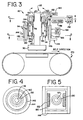
- FIGS. 3-5 illustrate one preferred spindle assembly 110 positioned above a linear belt polisher 170 where the electromagnetic force producing device includes a pair of linear motors 114 positioned on opposite sides of the spindle 112.
- the linear motors 114 are coupled to the spindle 112 via a first aerostatic bearing 130.
- the aerostatic bearing 130 creates an air cushion around the spindle 112 using a forced air supply 132 provided to a spindle assembly 110.
- the aerostatic bearing 130 also includes aerostatic thrust bearings 134, 136 that use the air cushion in cooperation with flanges 138, 140 extending radially from the spindle 112, to prevent undesired axial movement of the spindle along the spindles longitudinal axis.
- the first aerostatic bearing 130 preferably completely surrounds the circumference of the spindle over a predetermined length of the spindle 112.
- the first aerostatic bearing provides for substantially frictionless rotational motion of the spindle 112 about the spindle's longitudinal axis.
- a suitable aerostatic bearing is available from Six Degrees Consultants of Redwood City, California. In another embodiment, only one thrust bearing and one flange are necessary to obtain an appropriate level of substantially frictionless rotation.
- the linear motors 114 provide positional and force control along the longitudinal axis of the spindle 112.
- Each linear motor includes a stator 144 having multiple windings 146 that receive power from a voltage source 148.
- Each linear motor 114 also includes a rotor 150 mounted on a linear guide assembly 151 positioned coaxially around the spindle 112.
- the rotor magnet 152 on each rotor 150 is designed to cooperate with the coils 146 of the respective stator 144 mounted to a fixed frame (not shown). In operation, heat is generated by the linear motors 114.
- a water supply 166 may be used to pump water through cooling channels in each stator 144, adjacent to the coils 146, to remove excess heat.
- a second aerostatic bearing 142 maintains an air gap between the rotors 144 and stators 150 and substantially eliminates friction in the linear motors.
- the second aerostatic bearing 142 receives a flow of pressurized air, from a second forced air supply 156.
- the second aerostatic bearing reduces friction and accompanying frictional hysteresis in the spindle assembly 112.
- conventional linear rail bearings maybe used, aerostatic bearings are preferred because they are well suited to handle the high attraction forces generated between the rotor and the stator of the linear motors. Typical linear rail bearings produce a frictional hysteresis in excess of the force output resolution capable with the linear motor.
- the use of an aerostatic bearing 142 improves the radial runout characteristics of the spindle 112.
- the linear motors 114 may be any commercially available linear motor capable of producing pressure in a desired range at a workpiece.
- a linear motor having a resolution of approximately 2 microns and a linear force producing capability of 1350 lbf, such as part no. IC33-200A2-640-640-AC-HDIC-100-P1-TR available from Kollmorgen Co. of Madison Hills, California may be used.
- the air supplies may be any of a number of commercially available air pumps capable of maintaining a desired air pressure.
- the air gap generated by each of the aerostatic bearings is preferably at least 0.001 inches.
- the water supply may be any standard water circulation system capable of maintaining the operating temperature of the linear motors within a desired range.
- the spindle assembly 110 maybe used with a single linear motor mounted on one side of the spindle.
- a pair of linear motors 114 mounted on opposite sides of the spindle 112 (FIG. 3 and 4) is preferred because the opposing linear motors minimize the requirements for the second aerostatic bearing 142.
- Other groupings of linear motors mounted in a balanced fashion around the circumference of the spindle may also be used.
- Use of multiple linear motors would preferably include a separate servo controller for each linear motor where each servo controller maintains its own position and force feedback loops to account for the positional feedback and force control feedback necessary for each linear motor.
- the servo controlled, electromagnetic force producing device in this example a pair of linear motors 114, cooperates with the aerostatic bearings to present an essentially frictionless, highly controllable force/position system.
- the linear motors perform two functions. They apply a constant electromagnetic force directly to the spindle and they lower the spindle to a programmable height for polishing/buffing of a workpiece. They also allow for a force output resolution of at least P/2 n , where P is a maximum force produced by the electromagnetic force producing device and n is the output resolution of the servo controller 16 (FIG. 1) used to control the force producing device.
- the load cell in the wafer carrier 30 may be calibrated using a multi-point calibration over the full scale of the load cell. Additionally, the servo controller may be programmed to use linear interpolation, curve interpolation, or non-linear functions of any desired order to more accurately translate the signal received from the load cell and compensate for non-linear response properties.
- a single, cylindrical voice coil or cylindrical linear motor maybe used to provide additional balance of radial forces and simplify mounting issues.
- a cylindrical voice coil or cylindrical linear motor would also only require a single pair of feedback loops.
- the spindle 112 maybe rotated using a DC servo motor 158.
- the DC servo motor 158 would include a permanent magnet 160 mounted on the spindle itself and a coil 162 mounted to the rotor 150 of the linear motor.
- a power source 164 feeds the coil 162 of the DC servo motor 158.
- the DC servo motor 158 takes advantage of the first aerostatic bearing 132 to provide substantially frictionless rotational energy to the spindle.
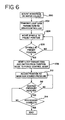
- FIG. 6 Utilizing the spindle assembly of FIG. 1, the operation of the spindle assembly 10 is illustrated in FIG. 6.
- a workpiece such as a semiconductor wafer, is mounted on a wafer holder removably attached to the spindle (at 200).
- the processor in the spindle assembly transmits operating parameters to the servo controller (at 202).
- the parameters include a set of position loop gain parameters and a set of force control gain parameters.
- the processor sets the force control gain parameters to zero and provides non-zero position loop gain parameters to the servo controller.
- the servo controller then moves the spindle linearly along the longitudinal axis of the spindle (at 204) until the spindle has traveled a predetermined distance that corresponds to the semiconductor wafer contacting the processing surface (at 206).
- the processor resets the gain parameters for the position feedback loop and the force control feedback loop so that the servo controller responds to load sense signals produced by the load cell (at 2 08).
- the processor accomplishes this by setting the position feedback loop gains to zero and the force control feedback gains to non-zero values.
- the position of the spindle is now adjusted based on force measured at the load cell so that the spindle will move to compensate when the desired pressure is not sensed (at 210, 212).
- the spindle assembly ceases the monitoring of applied force and backs the spindle away from the processing surface (at 214). Additionally, the semiconductor wafer or other workpiece may be rotated while being held against the processing surface by engaging the DC servo motor on the end of the spindle to rotate the spindle about the spindle's longitudinal axis.
- CMP chemical mechanical planarization
- Available CMP systems commonly called wafer polishers, often use a rotating wafer holder that brings the wafer into contact with a polishing pad moving in the plane of the wafer surface to be planarized.
- a polishing fluid such as a chemical polishing agent or slurry containing microabrasives, is applied to the polishing pad to polish the wafer.
- the wafer holder then presses the wafer against the linearly moving or rotating polishing pad and is rotated to polish and planarize the wafer.
- One suitable linear wafer polisher with which the spindle assembly may be used is the TERESTM polisher available from Lam Research Corporation in Fremont, California.
- One embodiment of the method includes the steps of moving the spindle towards a processing surface in gross movement increments with a force producing device by monitoring the spindle position with a position feedback loop. Once the workpiece attached to a holding device on the end of the spindle reaches the process surface, the gain parameters of the position feedback loop and a force control feedback loop are changed and the spindle assembly adjusts the position of the spindle based on force measurements.
- a spindle assembly for force controlled polishing is also disclosed.
- the spindle assembly includes a rotatable, axially movable spindle and a force producing device operatively coupled to the spindle.
- a servo controller is in communication with the force producing device and provides a control signal to the force producing device based on information from either a first feedback loop or a second feedback loop.
- the first feedback loop provides spindle position information and the second feedback loop provides information on pressure sensed at the workpiece mounted on the end of the spindle.
- the same force producing device is used to control spindle position in a first mode of operation and to maintain a constant force on the workpiece in a second mode of operation.
- the force producing device is preferably an electromagnetic force producing device such as one or more linear motors or voice coils.
- at least one aerostatic bearing is preferably used to minimize friction generated by longitudinal or rotational movement of the spindle.
Landscapes
- Engineering & Computer Science (AREA)
- Mechanical Engineering (AREA)
- General Physics & Mathematics (AREA)
- Manufacturing & Machinery (AREA)
- Physics & Mathematics (AREA)
- Automation & Control Theory (AREA)
- Human Computer Interaction (AREA)
- Condensed Matter Physics & Semiconductors (AREA)
- Computer Hardware Design (AREA)
- Microelectronics & Electronic Packaging (AREA)
- Power Engineering (AREA)
- Constituent Portions Of Griding Lathes, Driving, Sensing And Control (AREA)
- Mechanical Treatment Of Semiconductor (AREA)
Applications Claiming Priority (3)
| Application Number | Priority Date | Filing Date | Title |
|---|---|---|---|
| US09/385,769 US6083082A (en) | 1999-08-30 | 1999-08-30 | Spindle assembly for force controlled polishing |
| US385769 | 1999-08-30 | ||
| PCT/US2000/021843 WO2001015862A1 (en) | 1999-08-30 | 2000-08-11 | Spindle assembly for force controlled polishing |
Publications (2)
| Publication Number | Publication Date |
|---|---|
| EP1207981A1 EP1207981A1 (en) | 2002-05-29 |
| EP1207981B1 true EP1207981B1 (en) | 2004-01-07 |
Family
ID=23522802
Family Applications (1)
| Application Number | Title | Priority Date | Filing Date |
|---|---|---|---|
| EP00955424A Expired - Lifetime EP1207981B1 (en) | 1999-08-30 | 2000-08-11 | Spindle assembly for force controlled polishing |
Country Status (7)
| Country | Link |
|---|---|
| US (1) | US6083082A (enExample) |
| EP (1) | EP1207981B1 (enExample) |
| JP (1) | JP4484413B2 (enExample) |
| KR (1) | KR100717477B1 (enExample) |
| DE (1) | DE60007642T2 (enExample) |
| TW (1) | TW480207B (enExample) |
| WO (1) | WO2001015862A1 (enExample) |
Families Citing this family (23)
| Publication number | Priority date | Publication date | Assignee | Title |
|---|---|---|---|---|
| US6705930B2 (en) | 2000-01-28 | 2004-03-16 | Lam Research Corporation | System and method for polishing and planarizing semiconductor wafers using reduced surface area polishing pads and variable partial pad-wafer overlapping techniques |
| US6340326B1 (en) | 2000-01-28 | 2002-01-22 | Lam Research Corporation | System and method for controlled polishing and planarization of semiconductor wafers |
| US6646364B1 (en) * | 2000-07-11 | 2003-11-11 | Honeywell International Inc. | MEMS actuator with lower power consumption and lower cost simplified fabrication |
| US6755723B1 (en) | 2000-09-29 | 2004-06-29 | Lam Research Corporation | Polishing head assembly |
| US6812583B2 (en) | 2002-02-19 | 2004-11-02 | Rockwell Scientific Licensing, Llc | Electrical generator with ferrofluid bearings |
| US7288860B2 (en) * | 2002-02-19 | 2007-10-30 | Teledyne Licensing, Inc. | Magnetic transducer with ferrofluid end bearings |
| US20030154923A1 (en) * | 2002-02-19 | 2003-08-21 | Innovative Technology Licensing, Llc | Mechanical translator with ultra low friction ferrofluid bearings |
| US6812598B2 (en) * | 2002-02-19 | 2004-11-02 | Rockwell Scientific Licensing, Llc | Multiple magnet transducer with differential magnetic strengths |
| US6768230B2 (en) * | 2002-02-19 | 2004-07-27 | Rockwell Scientific Licensing, Llc | Multiple magnet transducer |
| US6766679B1 (en) * | 2002-03-27 | 2004-07-27 | Lam Research Corporation | System and method for spindle drive downforce calibration |
| US6798090B2 (en) * | 2002-04-18 | 2004-09-28 | Rockwell Scientific Licensing, Llc | Electrical power generation by coupled magnets |
| US6935938B1 (en) | 2004-03-31 | 2005-08-30 | Lam Research Corporation | Multiple-conditioning member device for chemical mechanical planarization conditioning |
| US7040955B1 (en) * | 2005-01-28 | 2006-05-09 | Strasbaugh | Chemical-mechanical planarization tool force calibration method and system |
| JP2008246628A (ja) * | 2007-03-30 | 2008-10-16 | Disco Abrasive Syst Ltd | チャックテーブル機構 |
| JP4327880B2 (ja) * | 2008-01-04 | 2009-09-09 | ファナック株式会社 | ゲイン自動調整機能を備えたサーボモータ制御装置 |
| JP5306065B2 (ja) * | 2009-06-04 | 2013-10-02 | 株式会社荏原製作所 | ドレッシング装置およびドレッシング方法 |
| US8408082B2 (en) * | 2009-11-18 | 2013-04-02 | General Electric Company | Apparatus to measure fluids in a conduit |
| JP5895154B2 (ja) * | 2011-01-21 | 2016-03-30 | パナソニックIpマネジメント株式会社 | リニアアクチュエータの駆動方法 |
| US8550876B2 (en) | 2011-08-08 | 2013-10-08 | Apple Inc. | Force-controlled surface finishing through the use of a passive magnetic constant-force device |
| CN103586772B (zh) * | 2012-08-16 | 2016-01-06 | 鸿富锦精密工业(深圳)有限公司 | 压力检测装置 |
| SG11201407527PA (en) * | 2013-01-30 | 2014-12-30 | Akribis Systems Pte Ltd | A planar positioning system and method of using the same |
| CN110315421B (zh) * | 2019-08-20 | 2023-12-26 | 江苏集萃精凯高端装备技术有限公司 | 一种晶体材料均一化抛光装置及使用方法 |
| JP7431589B2 (ja) * | 2020-01-17 | 2024-02-15 | 株式会社ディスコ | 加工装置 |
Family Cites Families (27)
| Publication number | Priority date | Publication date | Assignee | Title |
|---|---|---|---|---|
| US3631634A (en) * | 1970-01-26 | 1972-01-04 | John L Weber | Polishing machine |
| US3691694A (en) * | 1970-11-02 | 1972-09-19 | Ibm | Wafer polishing machine |
| US3903653A (en) * | 1973-04-11 | 1975-09-09 | Harold J Imhoff | Lapping machine |
| DE2451549A1 (de) * | 1974-10-30 | 1976-08-12 | Mueller Georg Kugellager | Belade- und entladevorrichtung fuer plattenfoermige halbleitermaterialien |
| US4009539A (en) * | 1975-06-16 | 1977-03-01 | Spitfire Tool & Machine Co., Inc. | Lapping machine with vacuum workholder |
| US4020600A (en) * | 1976-08-13 | 1977-05-03 | Spitfire Tool & Machine Co., Inc. | Polishing fixture |
| US4141180A (en) * | 1977-09-21 | 1979-02-27 | Kayex Corporation | Polishing apparatus |
| US4450652A (en) * | 1981-09-04 | 1984-05-29 | Monsanto Company | Temperature control for wafer polishing |
| JPS59161262A (ja) * | 1983-03-04 | 1984-09-12 | Masanori Kunieda | 磁気吸引式研摩方法 |
| US4593495A (en) * | 1983-11-25 | 1986-06-10 | Toshiba Machine Co., Ltd. | Polishing machine |
| DE3479936D1 (en) * | 1983-12-12 | 1989-11-02 | Unisys Corp | Air bearing for moving webs |
| GB8402194D0 (en) * | 1984-01-27 | 1984-02-29 | Secr Defence | Chemical polishing apparatus |
| US4680893A (en) * | 1985-09-23 | 1987-07-21 | Motorola, Inc. | Apparatus for polishing semiconductor wafers |
| DK155299B (da) * | 1986-04-18 | 1989-03-20 | Struers As | Apparat til slibning eller polering af emner |
| CH684321A5 (de) * | 1988-04-07 | 1994-08-31 | Arthur Werner Staehli | Einrichtung an einer Zweischeibenläppmaschine. |
| JPH01310859A (ja) * | 1988-06-09 | 1989-12-14 | Toyoda Mach Works Ltd | ポリシング加工機 |
| US4934102A (en) * | 1988-10-04 | 1990-06-19 | International Business Machines Corporation | System for mechanical planarization |
| JP2827540B2 (ja) * | 1991-03-11 | 1998-11-25 | 松下電器産業株式会社 | 研磨スピンドル |
| FR2677292B1 (fr) * | 1991-06-04 | 1995-12-08 | Seva | Machine de polissage a regulation pneumatique de l'effort de l'outil de la piece a polir. |
| FR2677291B1 (fr) * | 1991-06-06 | 1995-12-15 | Commissariat Energie Atomique | Machine de polissage a controle de pression. |
| US5148632A (en) * | 1991-06-14 | 1992-09-22 | Corning Incorporated | Cavity forming in plastic body |
| JP3227199B2 (ja) * | 1992-05-18 | 2001-11-12 | 株式会社リコー | 廃トナーの処理方法 |
| US5658183A (en) * | 1993-08-25 | 1997-08-19 | Micron Technology, Inc. | System for real-time control of semiconductor wafer polishing including optical monitoring |
| US5456627A (en) * | 1993-12-20 | 1995-10-10 | Westech Systems, Inc. | Conditioner for a polishing pad and method therefor |
| US5643044A (en) * | 1994-11-01 | 1997-07-01 | Lund; Douglas E. | Automatic chemical and mechanical polishing system for semiconductor wafers |
| US5618447A (en) * | 1996-02-13 | 1997-04-08 | Micron Technology, Inc. | Polishing pad counter meter and method for real-time control of the polishing rate in chemical-mechanical polishing of semiconductor wafers |
| JPH1071560A (ja) * | 1996-08-27 | 1998-03-17 | Speedfam Co Ltd | ウエハ加圧装置 |
-
1999
- 1999-08-30 US US09/385,769 patent/US6083082A/en not_active Expired - Lifetime
-
2000
- 2000-08-11 WO PCT/US2000/021843 patent/WO2001015862A1/en not_active Ceased
- 2000-08-11 JP JP2001520259A patent/JP4484413B2/ja not_active Expired - Fee Related
- 2000-08-11 EP EP00955424A patent/EP1207981B1/en not_active Expired - Lifetime
- 2000-08-11 DE DE60007642T patent/DE60007642T2/de not_active Expired - Fee Related
- 2000-08-11 KR KR1020027002464A patent/KR100717477B1/ko not_active Expired - Fee Related
- 2000-08-29 TW TW089117518A patent/TW480207B/zh not_active IP Right Cessation
Also Published As
| Publication number | Publication date |
|---|---|
| DE60007642D1 (de) | 2004-02-12 |
| WO2001015862A1 (en) | 2001-03-08 |
| JP2003508237A (ja) | 2003-03-04 |
| TW480207B (en) | 2002-03-21 |
| KR100717477B1 (ko) | 2007-05-14 |
| KR20020027583A (ko) | 2002-04-13 |
| DE60007642T2 (de) | 2004-10-07 |
| US6083082A (en) | 2000-07-04 |
| EP1207981A1 (en) | 2002-05-29 |
| JP4484413B2 (ja) | 2010-06-16 |
Similar Documents
| Publication | Publication Date | Title |
|---|---|---|
| EP1207981B1 (en) | Spindle assembly for force controlled polishing | |
| US9427844B2 (en) | Centering machine for workpieces, particularly optical lenses | |
| EP1506836B1 (en) | Machining apparatus | |
| US7189143B2 (en) | Machine for superfinishing by honing | |
| US5951368A (en) | Polishing apparatus | |
| US5076026A (en) | Microscopic grinding method and microscopic grinding device | |
| US12109667B2 (en) | Spindle unit and processing apparatus | |
| KR19980080910A (ko) | 연삭기 및 연삭방법 | |
| KR100356440B1 (ko) | 연마기 | |
| JPH01501297A (ja) | 不規則な回転面を仕上げるため及びサーボ制御機械加工を行うための超精密機械加工方法及び装置 | |
| US20060035564A1 (en) | Fine force actuator assembly for chemical mechanical polishing apparatuses | |
| US6881918B2 (en) | Electric discharge machining apparatus | |
| CA1075006A (en) | Tilt infeed by eccentric wheelhead support | |
| JP2000127024A (ja) | ポリッシング装置及び研磨加工方法 | |
| JPH0319031B2 (enExample) | ||
| JP3099678B2 (ja) | オンラインロール研削装置及びその制御方法 | |
| JP2000042867A (ja) | 回転型位置決め装置 | |
| CN223700274U (zh) | 晶圆减薄装置及系统 | |
| JP2000042900A (ja) | Cmp研磨装置 | |
| JPH10545A (ja) | 研磨ヘッド | |
| JP2000052234A (ja) | 研磨装置 | |
| JP2019147207A (ja) | 研削装置及び研削加工方法 | |
| JPH01310859A (ja) | ポリシング加工機 | |
| JP2000084846A (ja) | ウェーハ面取り装置 | |
| JPH03234469A (ja) | 研磨装置 |
Legal Events
| Date | Code | Title | Description |
|---|---|---|---|
| PUAI | Public reference made under article 153(3) epc to a published international application that has entered the european phase |
Free format text: ORIGINAL CODE: 0009012 |
|
| 17P | Request for examination filed |
Effective date: 20020228 |
|
| AK | Designated contracting states |
Kind code of ref document: A1 Designated state(s): DE FR GB IT |
|
| AX | Request for extension of the european patent |
Free format text: AL;LT;LV;MK;RO;SI |
|
| 17Q | First examination report despatched |
Effective date: 20020620 |
|
| GRAH | Despatch of communication of intention to grant a patent |
Free format text: ORIGINAL CODE: EPIDOS IGRA |
|
| GRAH | Despatch of communication of intention to grant a patent |
Free format text: ORIGINAL CODE: EPIDOS IGRA |
|
| GRAA | (expected) grant |
Free format text: ORIGINAL CODE: 0009210 |
|
| AK | Designated contracting states |
Kind code of ref document: B1 Designated state(s): DE FR GB IT |
|
| REG | Reference to a national code |
Ref country code: GB Ref legal event code: FG4D |
|
| REG | Reference to a national code |
Ref country code: IE Ref legal event code: FG4D |
|
| REF | Corresponds to: |
Ref document number: 60007642 Country of ref document: DE Date of ref document: 20040212 Kind code of ref document: P |
|
| LTIE | Lt: invalidation of european patent or patent extension |
Effective date: 20040107 |
|
| ET | Fr: translation filed | ||
| PLBE | No opposition filed within time limit |
Free format text: ORIGINAL CODE: 0009261 |
|
| STAA | Information on the status of an ep patent application or granted ep patent |
Free format text: STATUS: NO OPPOSITION FILED WITHIN TIME LIMIT |
|
| 26N | No opposition filed |
Effective date: 20041008 |
|
| REG | Reference to a national code |
Ref country code: IE Ref legal event code: MM4A |
|
| PGFP | Annual fee paid to national office [announced via postgrant information from national office to epo] |
Ref country code: GB Payment date: 20070830 Year of fee payment: 8 |
|
| PGFP | Annual fee paid to national office [announced via postgrant information from national office to epo] |
Ref country code: DE Payment date: 20071001 Year of fee payment: 8 Ref country code: IT Payment date: 20070828 Year of fee payment: 8 |
|
| PGFP | Annual fee paid to national office [announced via postgrant information from national office to epo] |
Ref country code: FR Payment date: 20070817 Year of fee payment: 8 |
|
| GBPC | Gb: european patent ceased through non-payment of renewal fee |
Effective date: 20080811 |
|
| REG | Reference to a national code |
Ref country code: FR Ref legal event code: ST Effective date: 20090430 |
|
| PG25 | Lapsed in a contracting state [announced via postgrant information from national office to epo] |
Ref country code: FR Free format text: LAPSE BECAUSE OF NON-PAYMENT OF DUE FEES Effective date: 20080901 Ref country code: IT Free format text: LAPSE BECAUSE OF NON-PAYMENT OF DUE FEES Effective date: 20080811 Ref country code: DE Free format text: LAPSE BECAUSE OF NON-PAYMENT OF DUE FEES Effective date: 20090303 |
|
| PG25 | Lapsed in a contracting state [announced via postgrant information from national office to epo] |
Ref country code: GB Free format text: LAPSE BECAUSE OF NON-PAYMENT OF DUE FEES Effective date: 20080811 |