EP1207680A2 - Bildaufnahmegerät - Google Patents
Bildaufnahmegerät Download PDFInfo
- Publication number
- EP1207680A2 EP1207680A2 EP01308044A EP01308044A EP1207680A2 EP 1207680 A2 EP1207680 A2 EP 1207680A2 EP 01308044 A EP01308044 A EP 01308044A EP 01308044 A EP01308044 A EP 01308044A EP 1207680 A2 EP1207680 A2 EP 1207680A2
- Authority
- EP
- European Patent Office
- Prior art keywords
- image
- communication
- wireless communication
- destination
- data
- Prior art date
- Legal status (The legal status is an assumption and is not a legal conclusion. Google has not performed a legal analysis and makes no representation as to the accuracy of the status listed.)
- Granted
Links
- 238000004891 communication Methods 0.000 claims abstract description 273
- 230000005540 biological transmission Effects 0.000 claims description 51
- 238000000034 method Methods 0.000 claims description 40
- 230000006870 function Effects 0.000 description 13
- 238000012545 processing Methods 0.000 description 7
- 238000012546 transfer Methods 0.000 description 7
- 238000001514 detection method Methods 0.000 description 6
- 238000010586 diagram Methods 0.000 description 6
- 230000003287 optical effect Effects 0.000 description 6
- 239000004973 liquid crystal related substance Substances 0.000 description 3
- 238000001228 spectrum Methods 0.000 description 3
- 230000006835 compression Effects 0.000 description 2
- 238000007906 compression Methods 0.000 description 2
- 230000002093 peripheral effect Effects 0.000 description 2
- 230000004044 response Effects 0.000 description 2
- 239000004065 semiconductor Substances 0.000 description 2
- 230000003044 adaptive effect Effects 0.000 description 1
- 238000006243 chemical reaction Methods 0.000 description 1
- 238000011161 development Methods 0.000 description 1
- 239000000284 extract Substances 0.000 description 1
Images


Classifications
-
- H—ELECTRICITY
- H04—ELECTRIC COMMUNICATION TECHNIQUE
- H04N—PICTORIAL COMMUNICATION, e.g. TELEVISION
- H04N1/00—Scanning, transmission or reproduction of documents or the like, e.g. facsimile transmission; Details thereof
- H04N1/21—Intermediate information storage
- H04N1/2104—Intermediate information storage for one or a few pictures
- H04N1/2112—Intermediate information storage for one or a few pictures using still video cameras
-
- H—ELECTRICITY
- H04—ELECTRIC COMMUNICATION TECHNIQUE
- H04N—PICTORIAL COMMUNICATION, e.g. TELEVISION
- H04N1/00—Scanning, transmission or reproduction of documents or the like, e.g. facsimile transmission; Details thereof
- H04N1/21—Intermediate information storage
- H04N1/2104—Intermediate information storage for one or a few pictures
- H04N1/2158—Intermediate information storage for one or a few pictures using a detachable storage unit
-
- H—ELECTRICITY
- H04—ELECTRIC COMMUNICATION TECHNIQUE
- H04N—PICTORIAL COMMUNICATION, e.g. TELEVISION
- H04N23/00—Cameras or camera modules comprising electronic image sensors; Control thereof
- H04N23/60—Control of cameras or camera modules
- H04N23/617—Upgrading or updating of programs or applications for camera control
-
- H—ELECTRICITY
- H04—ELECTRIC COMMUNICATION TECHNIQUE
- H04N—PICTORIAL COMMUNICATION, e.g. TELEVISION
- H04N23/00—Cameras or camera modules comprising electronic image sensors; Control thereof
- H04N23/60—Control of cameras or camera modules
- H04N23/66—Remote control of cameras or camera parts, e.g. by remote control devices
- H04N23/661—Transmitting camera control signals through networks, e.g. control via the Internet
-
- H—ELECTRICITY
- H04—ELECTRIC COMMUNICATION TECHNIQUE
- H04N—PICTORIAL COMMUNICATION, e.g. TELEVISION
- H04N5/00—Details of television systems
- H04N5/76—Television signal recording
- H04N5/765—Interface circuits between an apparatus for recording and another apparatus
- H04N5/77—Interface circuits between an apparatus for recording and another apparatus between a recording apparatus and a television camera
-
- H—ELECTRICITY
- H04—ELECTRIC COMMUNICATION TECHNIQUE
- H04N—PICTORIAL COMMUNICATION, e.g. TELEVISION
- H04N1/00—Scanning, transmission or reproduction of documents or the like, e.g. facsimile transmission; Details thereof
- H04N1/00127—Connection or combination of a still picture apparatus with another apparatus, e.g. for storage, processing or transmission of still picture signals or of information associated with a still picture
- H04N1/00281—Connection or combination of a still picture apparatus with another apparatus, e.g. for storage, processing or transmission of still picture signals or of information associated with a still picture with a telecommunication apparatus, e.g. a switched network of teleprinters for the distribution of text-based information, a selective call terminal
- H04N1/00307—Connection or combination of a still picture apparatus with another apparatus, e.g. for storage, processing or transmission of still picture signals or of information associated with a still picture with a telecommunication apparatus, e.g. a switched network of teleprinters for the distribution of text-based information, a selective call terminal with a mobile telephone apparatus
-
- H—ELECTRICITY
- H04—ELECTRIC COMMUNICATION TECHNIQUE
- H04N—PICTORIAL COMMUNICATION, e.g. TELEVISION
- H04N2101/00—Still video cameras
-
- H—ELECTRICITY
- H04—ELECTRIC COMMUNICATION TECHNIQUE
- H04N—PICTORIAL COMMUNICATION, e.g. TELEVISION
- H04N2201/00—Indexing scheme relating to scanning, transmission or reproduction of documents or the like, and to details thereof
- H04N2201/0008—Connection or combination of a still picture apparatus with another apparatus
- H04N2201/0013—Arrangements for the control of the connected apparatus by the still picture apparatus
-
- H—ELECTRICITY
- H04—ELECTRIC COMMUNICATION TECHNIQUE
- H04N—PICTORIAL COMMUNICATION, e.g. TELEVISION
- H04N2201/00—Indexing scheme relating to scanning, transmission or reproduction of documents or the like, and to details thereof
- H04N2201/0008—Connection or combination of a still picture apparatus with another apparatus
- H04N2201/0034—Details of the connection, e.g. connector, interface
- H04N2201/0048—Type of connection
- H04N2201/0055—By radio
-
- H—ELECTRICITY
- H04—ELECTRIC COMMUNICATION TECHNIQUE
- H04N—PICTORIAL COMMUNICATION, e.g. TELEVISION
- H04N2201/00—Indexing scheme relating to scanning, transmission or reproduction of documents or the like, and to details thereof
- H04N2201/0077—Types of the still picture apparatus
- H04N2201/0086—Image transceiver
-
- H—ELECTRICITY
- H04—ELECTRIC COMMUNICATION TECHNIQUE
- H04N—PICTORIAL COMMUNICATION, e.g. TELEVISION
- H04N5/00—Details of television systems
- H04N5/76—Television signal recording
- H04N5/765—Interface circuits between an apparatus for recording and another apparatus
- H04N5/77—Interface circuits between an apparatus for recording and another apparatus between a recording apparatus and a television camera
- H04N5/772—Interface circuits between an apparatus for recording and another apparatus between a recording apparatus and a television camera the recording apparatus and the television camera being placed in the same enclosure
-
- H—ELECTRICITY
- H04—ELECTRIC COMMUNICATION TECHNIQUE
- H04N—PICTORIAL COMMUNICATION, e.g. TELEVISION
- H04N5/00—Details of television systems
- H04N5/76—Television signal recording
- H04N5/78—Television signal recording using magnetic recording
- H04N5/781—Television signal recording using magnetic recording on disks or drums
-
- H—ELECTRICITY
- H04—ELECTRIC COMMUNICATION TECHNIQUE
- H04N—PICTORIAL COMMUNICATION, e.g. TELEVISION
- H04N5/00—Details of television systems
- H04N5/76—Television signal recording
- H04N5/907—Television signal recording using static stores, e.g. storage tubes or semiconductor memories
-
- H—ELECTRICITY
- H04—ELECTRIC COMMUNICATION TECHNIQUE
- H04N—PICTORIAL COMMUNICATION, e.g. TELEVISION
- H04N5/00—Details of television systems
- H04N5/76—Television signal recording
- H04N5/91—Television signal processing therefor
- H04N5/92—Transformation of the television signal for recording, e.g. modulation, frequency changing; Inverse transformation for playback
- H04N5/926—Transformation of the television signal for recording, e.g. modulation, frequency changing; Inverse transformation for playback by pulse code modulation
- H04N5/9261—Transformation of the television signal for recording, e.g. modulation, frequency changing; Inverse transformation for playback by pulse code modulation involving data reduction
- H04N5/9264—Transformation of the television signal for recording, e.g. modulation, frequency changing; Inverse transformation for playback by pulse code modulation involving data reduction using transform coding
Definitions
- the present invention relates to an image sensing device.
- the image data is temporarily transferred from the digital camera to, e.g., a personal computer, and the transferred image data is transmitted to a desired address by an image transmission function of the personal computer.
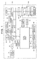
- Fig. 1 is a block diagram showing an arrangement of an image sensing device
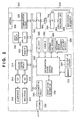
- Fig. 2 is a block diagram showing an arrangement of a communication device
- Fig. 3 is a perspective view showing an outer appearance of an image communication system built by the image sensing device in Fig. 1 and the communication device in Fig. 2
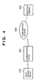
- Fig. 4 is a block diagram showing an overall arrangement of the image communication system built by the image sensing device in Fig. 1 and the communication device in Fig. 2.
- an image communication system is built by an image sensing device 100 and communication device 300, which are connected via a wireless channel.
- the communication device 300 is connected to a communication network 400, and an image sensed by the image sensing device 100 can be sent to a reception terminal 500 via the communication network 400.
- the image sensing device 100 exchanges data containing commands and a sensed image via antennas 112 and 332, respectively located in each device.
- Wireless communication between the image sensing device 100 and communication device 300 is attained by a spread spectrum scheme such as Bluetooth.
- Bluetooth is a wireless communication scheme which uses the 2.4-GHz frequency band, requires little electric power, and is suitable for near-distance communications, and can obtain a high transmission rate ranging from 500 kbps to 1 Mbps.
- an infrared communication scheme such as IrDA may be used in place of that wireless communication scheme.
- the image sensing device 100 stores image data sensed via a photographing lens 10 on a recording medium 120, and sends the image data via the antenna 112.
- the communication device 300 receives image data via the antenna 332, and sends the received image data by an antenna 328 to the reception terminal 500 via a communication base station accommodated in the communication network 400, and the communication network 400.
- the image sensing device 100 (refer to Fig. 1) is a digital camera.
- the photographing lens 10 comprises an optical lens group for capturing an optical image of an object.
- An image sensing element 14 converts an optical image captured via the photographing lens 10 into electrical signals, and an A/D converter 16 converts the analog signal output from the image sensing element 14 into a digital signal and outputs the digital signal as image data.
- An image processing circuit 20 executes a predetermined pixel interpolation process and color conversion process for image data from the A/D converter 16 or a memory control circuit 22.
- Image data from the A/D converter 16 is written in an image display memory 24 or memory 30 via the image processing circuit 20 and memory control circuit 22 or directly via the memory control circuit 22.
- An image display 28 comprises a TFT LCD (TFT liquid crystal display panel) or the like. Display image data written in the image display memory 24 is converted by a D/A converter 26 into an analog video signal, which is inputted to and displayed by the image display 28. When sensed image data is displayed using the image display 28, a digital viewfinder function can be implemented.
- the memory 30 comprises a volatile memory and/or nonvolatile memory for storing sensed still image and moving image data, and has a storage capacity large enough to store a predetermined number of still images or a moving image for a predetermined period of time.
- the memory 30 is also used as a work area of a system control circuit 50.
- a compression/expansion circuit 32 compresses/expands image data by, e.g., adaptive discrete cosine transform (ADCT).
- the circuit 32 compresses/expands an image read from the memory 30, and writes the compressed/expanded data in the memory 30.
- ADCT adaptive discrete cosine transform
- the system control circuit 50 controls the overall image sensing device 100.
- a memory 52 stores constants, variables, programs, and the like required for operating the system control circuit 50.
- An indicator 54 comprises a liquid crystal display, speaker, and the like for displaying the operation state, messages, and the like using text, icons, sound, and the like in accordance with execution of programs by the system control circuit 50, and is constructed by one or a plurality of elements which are set at easy-to-see positions around a console 70 of the image sensing device 100, and include a combination of an LCD, LEDs, sound generation element, and the like. Some of the displayed information shown in indicator 54 are shown in an optical viewfinder 104.
- a nonvolatile memory 56 is an electrically erasable/recordable memory, and uses, e.g., an EEPROM or the like.
- Identification information 58 stores various kinds of identification information used in authentication prior to communicating with the communication device 300 via a communication circuit 110 and the antenna 112.
- Shutter switch 64 and the console 70 are used to input various operation instructions of the system control circuit 50, and comprise a combination of one or a plurality of switches, dials, a touch panel, pointing by means of line-of-sight detection, a speech recognition device, and the like.
- the shutter switch 64 is turned ON when a shutter button 62 (Fig. 3) is pressed to its full-stroke position, and instructs start of a series of processes including an exposure process for writing a signal read from the image sensing element 14 in the memory 30 as image data via the A/D converter 16 and memory control circuit 22, a development process using arithmetic operations by the image processing circuit 20 and memory control circuit 22, and a recording process for compressing image data read out from the memory 30 by the compression/expansion circuit 32, and writing the compressed image data in the recording medium 120.
- the console 70 comprises various buttons, a touch panel, and the like, which include a power switch, menu button, set button, menu move + (plus) button, menu move - (minus) button, playback image move + (plus) button, a playback image move - (minus) button, a playback switch capable of setting various function modes such as a playback mode/minus screen playback ⁇ erase mode/PC connect mode, and the like, and so on.
- a rotary dial switch may be used to select numerical values and functions.
- the optical viewfinder 104 allows photographing without using the digital viewfinder function by means of the image display 28.
- the communication circuit 110 has a near-distance, high-speed data communication function based on a spread spectrum communication scheme such as Bluetooth or the like.
- An interface 128 interfaces with the recording medium 120 such as a memory card, hard disk, or the like, and a connector 127 connects the recording medium 120.
- this embodiment has one set of interface and connector that receive the recording media.
- a plurality of sets of interfaces and connectors may be used.
- combinations of interfaces and connectors of different standards may be used.
- PCMCIA Personal Computer Memory Card International Association
- CF compact flash
- MMC multimedia card
- interface 128 and connector 127 comply with the standards of a PCMCIA card, CF card, and the like, and various communication cards such as a LAN card, modem card, USB card, IEEE (Institute of Electrical and Electronic Engineers) 1394 card, P1284 card, SCSI (Small Computer System Interface) card, PHS, and the like are connected thereto, image data and associated management information can be transferred between the image sensing device and an external computer or its peripheral devices such as a printer and the like.
- PCMCIA Peripheral Component Interconnect Express
- the recording medium 120 comprises a recording unit 122 comprised of a semiconductor memory, magnetic disk, or the like, an interface 124 with the image sensing device 100, a connector 126 for connecting the image sensing device 100, and identification information 129.
- the communication device 300 is a portable telephone.
- Microphone 310 converts a voice into an electrical signal
- an A/D converter 312 converts an analog signal outputted from the microphone 310 into a digital signal and outputs the digital signal as audio data.
- Memory control circuit 314 controls read/write of audio data from the A/D converter 312 from/in a memory 320, and also input of data read out from the memory 320 to a D/A converter 316.
- the D/A converter 316 converts audio data into an analog signal, and inputs the analog signal to a speaker 318.
- the speaker 318 converts the input analog signal into a voice signal, and outputs voice.
- the memory 320 stores audio data input via the microphone 310, and a still image or moving image sent from the image sensing device 100, and has a storage size large enough to store a predetermined number of still images or a moving image for a predetermined period of time.
- D/A converter 322 converts still image data or moving image data stored in the memory 320 into an analog signal, and outputs the analog signal to an image display 324 as an image signal.
- the image display 324 displays an image signal from the D/A converter 322.
- Communication circuit 326 has a far-distance wireless communication function such as TDMA (Time Division Multiple Access), CDMA (Code Division Multiple Access), W-CDMA (Wide-band Code Division Multiple Access), or the like, and connects the communication device 300 to another communication device and/or communication base station via the antenna 328 and a wireless channel.
- TDMA Time Division Multiple Access
- CDMA Code Division Multiple Access
- W-CDMA Wide-band Code Division Multiple Access
- Communication circuit 330 has a near-distance, high-speed data communication function based on the Bluetooth spread spectrum communication, and connects the communication device 300 with another device via the antenna 332.
- Communication system control circuit 350 controls the overall communication device 300.
- Memory 352 stores constants, variables, programs, and the like required for operating the communication system control circuit 350.
- the nonvolatile memory 354 is an electrically erasable memory, and uses, e.g., an EEPROM or the like.
- Identification information 356 stores various kinds of identification information used for authentication prior to communication with the image sensing device 100 via the communication circuit 330 and antenna 332.
- Indicator 360 comprises a liquid crystal display, speaker, and the like for displaying the operation state, messages, and the like using text, icons, sound, and the like in accordance with execution of programs by the communication system control circuit 350, and is constructed by one or a plurality of elements which are set at easy-to-see positions around a console 362 of the communication device 300, and include a combination of an LCD, LEDs, sound generation element, and the like.
- the console 362 is used to input various operation instructions of the communication system control circuit 350, and comprises a combination of one or a plurality of switches, dials, a touch panel, pointing by means of line-of-sight detection, a speech recognition device, and the like.
- the console 362 allows operations such as power ON/OFF of the communication device 300, execution (off-hook)/stop (on-hook) of telephone conversation, telephone number input, telephone number search, switching of communication modes, and the like.
- Incoming call notifier 364 notifies the user of the communication device 300 of an incoming call by a sound such as a ringing tone, voice, music, or the like and/or an image such as an icon, moving image, still image, light emission, or the like and/or vibration.
- Recording medium attachment/detachment detector 366 detects whether or not a recording medium 200 is attached to a connector 392.
- Interface 390 interfaces with the recording medium 200 such as a memory card, hard disk, or the like, and the connector 392 connects the recording medium 200.
- this embodiment has one set of interface and connector that receive the recording media.
- a plurality of sets of interfaces and connectors may be used.
- combinations of interfaces and connectors of different standards may be used.
- interface and connector those complying with the standards of a PCMCIA (Personal Computer Memory Card International Association) card, CF (compact flash) card, MMC (multimedia card), and the like may be used. Furthermore, when the interface 390 and connector 392 use those complying with the standards of a PCMCIA card, CF card, and the like, and various communication cards such as a LAN card, modem card, USB card, IEEE (Institute of Electrical and Electronic Engineers) 1394 card, P1284 card, SCSI (Small Computer System Interface) card, PHS, and the like are connected thereto, image data and associated management information can be transferred between the image sensing device and an external computer or its peripheral devices such as a printer and the like.
- PCMCIA Personal Computer Memory Card International Association
- CF compact flash
- MMC multimedia card
- image data and associated management information can be transferred between the image sensing device and an external computer or its peripheral devices such as a printer and the like.
- the recording medium 200 comprises a recording unit 202 comprised of a semiconductor memory, magnetic disk, or the like, an interface 204 with the communication device 300, a connector 206 for connecting the image sensing device 100, and identification information 208.
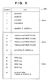
- Fig. 5 shows a storage allocation of the nonvolatile memory 354.
- an area 354a stores at addresses "0" to "3" as destination information telephone numbers of image communication partners, and also at address "8" information for designating a destination in a default mode. If “0" is stored at address "8”, the destination in the default mode is fixed to that stored at address "0". If “1" is stored at address "8”, the destination in the default mode is fixed to that stored at address "1".
- An area 354b stores at addresses "40" to "43" image saving location information for designating a location where the communication partner (reception terminal 500 in Fig. 4) saves a received image, and also at address "48" information for designating an image saving location in the default mode. If “0" is stored at address "48”, the storage location in the default mode is fixed to that stored at address "40". If “1" is stored at address "48”, the storage location in the default mode is fixed to that stored at address "41".
- An area 354c stores, e.g., file names at addresses "80" to "83” as transmission image designation information for designating the image to be sent, and also at address "88" information for designating a transmission image in the default mode. If “00” or “10” is stored at address “88”, the transmission image is fixed. If “00” is stored at address "88”, the transmission image is fixed to a latest sensed image; if “10” is stored at address "88", the transmission image is fixed to an image at address "80” (in this case, an image_0.jpg stored at address "80”).
- This embodiment can execute an image transmission mode for sending image data which is designated by the transmission image designation information from those sensed by the image sensing device 100 to the destination designated by the destination information via the communication device 300, and designating the saving location of the sent image data by the image saving location information.
- this embodiment has a mode for receiving image data sent from the image sensing device 100 by the communication device 300 and recording the received image data in the detachable recording medium 200.
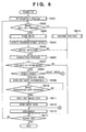
- Figs. 6 and 7 are flowcharts showing the operation sequence of the image sensing device shown in Fig. 1
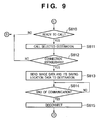
- Figs. 8 to 10 are flowcharts showing the operation sequence of the communication device shown in Fig. 2.
- Figs. 6 and 7 show the program steps stored in the memory 52 shown in Fig. 1, and the system control circuit 50 is a computer for reading out the programs from the memory 52 and executing the readout programs.
- the memory 52 is a storage medium which stores the programs so that the system control circuit 50 can read them out.
- the card type storage medium that stores the programs correspond to the storage medium which stores the programs so that the system control circuit 50 can read them out.
- the programs may be externally supplied to the system control circuit 50 via the antenna 112 and communication circuit 110.
- Figs. 8 to 10 show the program steps stored in the memory 352 shown in Fig. 2, and the communication system control circuit 350 is a computer for reading out the programs from the memory 352 and executing the readout programs.
- the memory 352 is a storage medium which stores the programs so that the communication system control circuit 350 can read them out.
- the card type storage medium that stores the programs correspond to the storage medium which stores the programs so that the communication system control circuit 350 can read them out.
- the programs may be externally supplied to the communication system control circuit 350 via the antenna 332 and communication circuit 330 or via the antenna 328 and communication circuit 326.
- step S601 when the power switch is turned ON, an initialization process is executed in step S601, and it is then checked in step S602 if an image send key has been pressed. If the image send key has not been pressed, the flow advances to step S615 to execute another process (e.g. an image sensing process or an image playback process), and the flow advances to step S614 to check if the power switch is turned OFF. If the power switch is turned off, the processing ends; otherwise, the flow returns to step S602.
- step S615 to execute another process (e.g. an image sensing process or an image playback process)
- step S614 to check if the power switch is turned OFF. If the power switch is turned off, the processing ends; otherwise, the flow returns to step S602.
- step S602 If it is detected in step S602 that the image send key has been pressed, the flow advances to step S603 to execute a mode setup process.
- this mode setup process one of the default mode and select mode is set as the image transmission mode using the console 70.
- an image is sent using destination information, image saving location information, and transmission image designation information which are fixed as default conditions.
- destination information, image saving location information, and transmission image designation information are selected from the image sensing device 100, and an image is sent using the selected information.
- step S604 The flow advances to step S604 to execute a device detection process for detecting a device with which the image sensing device can communicate via the communication circuit 110. It is checked on the basis of the detection result of the device detection process in step S605 if a device with which the image sensing device can communicate is detected. If a device with which the image sensing device can communicate is not detected, the flow jumps to step S614; otherwise, the flow advances to step S606.
- step S606 a connection process for establishing wireless connection with the detected device is executed.
- the detected device is the communication device 300, and the connection process with the communication device 300 is executed. It is checked in step S607 if connection with the communication device 300 is established. If connection is not established, the flow jumps to step S614; otherwise, the flow advances to step S608 to discriminate if the default or select mode is set.
- step S609 the flow advances to step S609 to send set mode information indicating that the default mode is set to the communication device 300 via the communication circuit 110.
- step S610 the control waits for reception of image designation data returned from the image communication device 300 in response to the set mode information, i.e., transmission image designation information fixed by default (in the example in Fig. 5, information that designates image data corresponding to image_0.jpg stored at address "80" of the nonvolatile memory 354 if information stored at address "88" of the nonvolatile memory 354 is "10").
- the set mode information i.e., transmission image designation information fixed by default (in the example in Fig. 5, information that designates image data corresponding to image_0.jpg stored at address "80" of the nonvolatile memory 354 if information stored at address "88" of the nonvolatile memory 354 is "10").
- step S611 When the communication circuit 110 receives the transmission image designation information fixed as a default, the flow advances to step S611 to read out image data designated by the transmission image designation information (image data corresponding to image_0.jpg when image data corresponding to it is designated) from the storage medium 120.
- step S612 the readout image data is sent to the communication device 300 via the communication circuit 110.
- step S613 the flow advances to step S613 to disconnect wireless connection with the communication device 300.
- step S614 the flow advances to step S614.
- the latest sensed image can be designated as a transmission image. This designation can be implemented by registering information "00" at address "88" of the nonvolatile memory 56.
- the image sensing device 100 Upon receiving information that designates the latest sensed image as a transmission image by the communication circuit 110, the image sensing device 100 sends the latest sensed image stored in the recording unit 122 to the communication device 300 via the communication circuit 110.
- step S608 If it is determined in step S608 that the select mode is set, the flow jumps to step S616 shown in Fig. 7.
- step S616 set mode information indicating that the select mode is set is sent to the communication device 300 via the communication circuit 110.
- step S617 the control waits for reception of transmission image, destination, and saving location designation data returned from the communication device 300 in response to the set mode information, i.e., all of transmission image designation information, destination information, and image saving location designation information (in the example of Fig. 5, all pieces of information stored at addresses "0", "1", “2", “3”, “40", “41", “42”, “43”, “80”, "81", “82”, and "83” of the nonvolatile memory 354).
- the set mode information i.e., all of transmission image designation information, destination information, and image saving location designation information
- step S618 Upon receiving all of the transmission image designation information, destination information, and image saving location designation information by the communication circuit 110, the flow advances to step S618 to display a transmission image selection screen on the image display 28.
- This transmission image selection screen displays a list of information, e.g., image file names corresponding to respective pieces of received transmission image designation information (in the example of Fig. 5, image_0.jpg, image_1.jpg, image_2.jpg, and image_3.jpg), and the user can designate image data to be sent by selecting a desired file name from those displayed in the list using the console 70.
- step S619 the control waits for completion of operation for selecting image data to be sent. Upon completion of this operation, information indicating the selected image data is held in the memory 30, and the flow then advances to step S620.
- a destination selection screen is displayed on the image display 28.
- the destination selection screen displays information corresponding to the received destination information, e.g., a list of telephone numbers (in the example of Fig. 5, 0337571234, 0354827234, 0441234567, and 070512345678), and the user can designate a destination by selecting a desired telephone number from those displayed in the list using the console 70.
- the control waits for completion of operation for selecting the destination in step S621. Upon completion of this operation, destination information corresponding to the selected telephone number is held in the memory 30, and the flow then advances to step S622.
- a saving location selection screen is displayed on the image display 28.
- the saving location selection screen displays a list of information corresponding to the received image saving location information (classes 1, 2, 3, and 4 in an image folder in My Documents shown in Fig. 5), and the user can designate an image saving location in the destination (the reception terminal 500 in Fig. 4) by selecting desired information from those in the list using the console 70.
- the control waits for completion of operation for selecting the image saving location in step S623. Upon completion of this operation, the selected image saving location information is held in the memory 30, and the flow advances to step S624.
- Image data designated by the transmission image designation information held in the memory 30 is read out from the storage medium 120 in step S624, and the readout image data, and the destination information and image saving location information held in the memory 30 are sent to the communication device 300 via the communication circuit 110 in step S625.
- the flow then advances to step S613 shown in Fig. 6 to disconnect wireless connection with the communication device 300.
- the flow advances to step S614.
- step S801 it is checked in step S801 if the communication circuit 330 has received a connection request from the image sensing device 100. If the communication circuit 330 has not received any connection request yet, the flow advances to step S820 to execute another process, and the flow returns to step S801.
- step S802 Upon receiving the connection request from the image sensing device 100, the flow advances to step S802 to execute a connection process for establishing wireless connection with the image sensing device 100 via the communication circuit 330. It is checked in step S803 if connection is established. If connection is not established, the flow returns to step S801. If connection is established, the communication device 300 is ready to communicate with the image sensing device 100 via a wireless channel, and waits for reception of set mode information from the image sensing device 100 in step S804. Upon receiving the set mode information by the communication circuit 330, the flow advances to step S805.
- step S806 it is checked, based on the received set mode information in step S805, if the default mode or select mode is set at the image sensing device 100. If the default mode is set at the image sensing device 100, the flow advances to step S806 to send transmission image designation data, i.e., transmission image designation information fixed as a default (in the example in Fig. 5, information for designating image_0.jpg stored at address "80” if information stored at address "88" of the nonvolatile memory 354 is "10") via the communication circuit 330.
- transmission image designation data i.e., transmission image designation information fixed as a default (in the example in Fig. 5, information for designating image_0.jpg stored at address "80” if information stored at address "88" of the nonvolatile memory 354 is "10"
- step S807 to wait for reception of image data sent from the image sensing device 100 (image data designated by the transmission image designation information fixed as a default, and image data corresponding to image_0.jpg stored at address "80” if information stored at address "88" of the nonvolatile memory 354 is “10” in the example in Fig. 5) via the communication circuit 330.
- image data sent from the image sensing device 100
- step S808 to wait for completion of the communication with the image sensing device 100.
- step S809 disconnection of wireless connection with the image sensing device 100 is confirmed in step S809, and the flow advances to step S810 in Fig. 9.
- step S810 It is checked in step S810 if the communication circuit 326 can originate a call to the communication network 400. If the communication circuit 326 cannot originate a call, the flow returns to step S801. If the communication circuit 326 can originate a call, the flow advances to step S811 to call the designated destination via the communication circuit 326. In this case, since the default mode is set, a call is placed to a destination designated by the destination information fixed as a default. In the example in Fig. 5, since a number at address "0" is set as a default destination at address "8" of the nonvolatile memory 354, a call is placed to a destination having a telephone number "0337571234" at address "0". This call originating signal is sent from the communication circuit 326 to a base station of the communication network 400 shown in Fig. 4.
- step S812 It is checked in step S812 if connection with the destination is established. If connection is not established, the flow returns to step S801. If connection is established, the flow advances to step S813 to send image data and its saving location data (i.e., image saving location information fixed as a default) to the destination (reception terminal 500 in Fig. 4) via the communication circuit 326.
- This image data and saving location data is sent to the reception terminal 500 via the base station of the communication network 400 (Fig. 4) and the communication network 400.
- the default saving location is a class 1 folder in the image folder in My Documents stored at address "40".
- an image sent from the communication circuit 326 to the partner via the communication network 400 is the image received in step S807.
- step S814 The flow advances to step S814 to wait for completion of the communication with the destination. Upon completion of the communication, the flow advances to step S815 to disconnect connection with the destination, and the flow returns to step S801.
- step S805 If it is determined in step S805 that the select mode is set, the flow advances to step S816 shown in Fig. 10.
- step S816 since the select mode is set, transmission image, destination, and saving location designation data, i.e., transmission image designation information, destination information, and image saving location information (all pieces of information stored at addresses "0", “1", “2", “3”, “40”, “41”, “42”, “43”, “80”, "81", “82”, and “83” of the nonvolatile memory 354) are read out and are sent to the image sensing device 100 via the communication circuit 330.
- step S817 the control waits for reception of image data, destination information, and image saving location information sent from the image sensing device 100 via the communication circuit 330. Upon receiving these data and information, the received information is stored in the memory 352 or recording unit 202, and the flow advances to step S818 to wait for completion of the communication with the image sensing device 100. Upon completion of the communication with the image sensing device 100, disconnection of wireless connection with the image sensing device 100 is confirmed in step S819, and the flow then advances to step S810 in Fig. 9.
- step S810 It is checked in step S810 if the communication circuit 326 can originate a call to the communication network 400. If the communication circuit 326 cannot originate a call, the flow returns to step S801. If the communication circuit 326 can originate a call, the flow advances to step S811 to call the designated destination via the communication circuit 326. In this case, since the select mode is set, a call is placed to the destination designated by the destination information received in step S817. In the example shown in Fig. 5, a call is placed to a destination having a telephone number selected from those at addresses "0" to "3".
- step S812 It is checked in step S812 if connection with the destination is established. If connection is not established, the flow returns to step S801. If connection is established, the flow advances to step S813 to send image data and its saving location data (i.e., image saving location information selected by the image sensing device 100 from those at addresses "40" to "43") to the destination (reception terminal 500 in Fig. 4) via the communication circuit 326.
- image data and its saving location data i.e., image saving location information selected by the image sensing device 100 from those at addresses "40" to "43
- the image sent from the communication circuit 326 to the partner via the communication network 400 is that received in step S817 and, likewise, the saving location data is that received in step S817.
- the reception terminal 500 saves the received image in the designated folder of classes 1 to 4 contained in the image folder in My Documents of its storage areas.
- step S814 The flow advances to step S814 to wait for completion of the communication with the destination. Upon completion of the communication, the flow advances to step S815 to disconnect with the destination, and the flow returns to step S801.
- the disconnection timing of wireless connection between the image sensing device 100 and communication device 300 is the completion timing of the communication between them.
- connection may be terminated at other possible timings and resending image data due to a communication error, upon successively transferring a plurality of image files, or upon successively transferring image data to different partners.
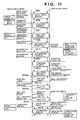
- a data transfer method according to the second embodiment of the present invention will be described below with reference to Fig. 11. Since a system which practices the data transfer method is constructed by the image sensing device 100, communication device 300, and public network as in the first embodiment, a description thereof will be omitted.
- Fig. 11 is a sequence chart showing wireless communication control in the image sensing device 100 and communication device 300, which practice the data transfer method according to the second embodiment.
- the image sensing device 100 saves destination designation information for designating a destination to which image data sensed by the image sensing device 100 is to be sent, and transmission image designation information for designating image data to be sent to the destination as a designation information file such as DPOF (Digital Print Order Format) or the like, and transfers the saved designation information file to the communication device 300 via a wireless communication using the communication circuit 110.
- the communication device 300 saves the transferred designation information file, extracts a file name of image data to be transferred from the designation information, and reads out image data at an arbitrary timing.
- image data can be acquired from the image sensing device in correspondence with the operation state of the communication device 300, and any image transfer failure caused by a busy state of the communication device can be avoided.
- the image sensing device 100 executes an initialization process, and then checks if the image send key has been pressed. If the image send key has been pressed, a mode setup process is executed. In this mode setup process, one of the default mode and select mode is set as the image transmission mode.
- an image is sent using fixed destination information, image saving location information, and transmission image designation information which are set in advance.
- destination information, image saving location information, and transmission image designation information are selected from the image sensing device 100, and an image is sent using the selected information.
- information set in advance or edited information is saved in a designation information file.
- a device detection process 1604 for detecting a device with which the image sensing device can communicate via the communication circuit 110 is executed (step S604). If a device with which the image sensing device can communicate is detected (step S605), a connection process 1606 for establishing wireless connection with a selected one of the detected devices is executed (step S606). In this case, the detected device is the communication device 300, and the connection process with the communication device 300 is executed. If connection is established in the lower layer, a host protocol 1607 checks performance. If the sequence of the present invention is installed in both the apparatus in the host protocol, connection is established (step S607).
- step S608 When connection is established, if the select mode is set (step S608), the host protocol 1607 sends set mode information indicating that the select mode is set from the communication circuit 110 to the communication device 300 (step S616), and the communication circuit 110 receives transmission image, destination, and saving location designation data from the communication device 300 (step S617). After that the processes in steps S606 to S623 are executed to select a transmission image, destination, and saving location.
- a designation information file transmission process 1625 is executed in place of the processes in steps S624 and S625.
- the communication device 300 Upon completion of transfer of this designation information file, the communication device 300 saves the designation information, and a disconnection sequence 1613 for disconnecting wireless connection between the image sensing device 100 and communication device 300 is executed (step S613).
- the designation information file contains information for designating a transmission image from image data sensed by the image sensing device 100, information for designating a destination to which image data is sent via the communication device 300, and information for designating the saving location of the sent image data.
- the information for designating the transmission image indicates a file name of the transmission image, and the designation information file does not contain any image data.
- the designation information file may contain a thumbnail as image data with a small data size.
- the communication device 300 displays the received thumbnail on the display 324.
- step S608 If it is determined in step S608 that the default mode is set, a transmission sequence 1625 of a designation information file containing information indicating the default mode from the communication circuit 110 to the communication device 300 is executed, and the disconnection sequence 1613 for disconnecting the wireless connection between the image sensing device 100 and communication device 300 is executed, in place of steps S609 to S612 (step S613).
- the communication device 300 executes a connection process 1606 (step S802).
- the host protocol 1607 receives the set mode information indicating the selected mode from the image sensing device (steps S804 and S805).
- the host protocol 1607 sends transmission image, destination, and saving location designation data from the communication circuit 330 to the image sensing device 100 (step S816), and the communication circuit 330 receives the designation information file of the selected mode from the image sensing device 100 and saves it in the memory 362 (step S817).
- the disconnection sequence 1613 for disconnecting with the image sensing device 100 is executed (step S819).
- step S804 If it is determined in step S804 that the image sensing device 100 is in the default mode, the default mode designation information file is received, and is saved in the memory 352 (step S805). In this embodiment, image data reception in steps S806 and S807 is skipped, and upon completion of the communication (step S808), a disconnection sequence 1613 for disconnecting with the image sensing device 100 is executed (step S809).
- the communication device 300 In the communication device 300 that saves the designation information file, it is checked if the designation information file contains a connection request from the image sensing device 100. If no connection request is received, another process (e.g. the standby process for an incoming call from the communication network 400) is executed.
- another process e.g. the standby process for an incoming call from the communication network 400
- a connection process 2802 for establishing wireless connection with the image sensing device 100 via the communication circuit 330 is executed. If connection is established in a sequence 2803 which is the same as that aforementioned sequence, the communication device 300 is ready to communicate with the image sensing device 100 via a wireless channel.
- the transmission image designation information is read out, image data is designated based on the transmission image designation information, image data requests 2816a,b,... are issued to the image sensing device 100, and image data 2817a, b, ... segmented into a plurality of packets are acquired from the image sensing device 100.
- the image data requests 2816a,b,... are repetitively sent until reception of image data is completed.
- the received image data is stored in the memory 352 or recording unit 202.
- information 2818 indicating if reception has ended normally is sent to the image sensing device 100.
- image data requests 2816a,b,... that request an image of a file name registered at address "88" of the nonvolatile memory 354 (in the example of Fig. 5, image data with a file name "image_0.jpg” stored at address "80" of the nonvolatile memory 354 if "10" is stored at address "88") is sent from the communication circuit 330 to the image sensing device 100 to receive that image data 2817a,b,... segmented into a plurality of packets. .
- the image data requests 2816a,b,... are repetitively sent until reception of image data is completed.
- the received image data is stored in the memory 352 or recording unit 202.
- information 2818 indicating if reception has ended is sent to the image sensing device 100.
- the image sensing device 100 Upon receiving the image data acquisition requests 2816a,b,..., the image sensing device 100 reads out the designated image from the storage medium 120, and sends the readout image data to the communication device 300 via the communication circuit 110. This sequence is repeated until all designated image data are transferred to the communication device 300.
- a disconnection sequence 2819 for disconnecting thewireless connection between the image sensing device 100 and communication device 300 is executed.
- the communication device 300 Upon completion of the communication of image data with the image sensing device 100, the communication device 300 executes the disconnection sequence 2819 for releasing the wireless channel with the image sensing device 100 irrespective of the mode selected (default or select mode). As in Fig. 9, it is checked if the communication device 300 can place a call to the communication network 400 (step S810). If a call can be placed, the communication circuit 326 calls the destination selected by the image sensing device 100 or a default destination stored at address "8" of the nonvolatile memory 354 (step S811). It is then checked if connection with the destination is established (step S812).
- image data received from the image sensing device 100 and the saving location data selected by the image sensing device 100 or default saving location data stored at address "48" of the nonvolatile memory 354 are sent to the destination via the communication circuit 326.
- the destination stores the received image data in a file specified by the saving location data.
- control then waits for completion of the communication with the destination (step S814). Upon completion of this communication, connection with the destination is disconnected (step S815), thus ending a series of operations.
- the communication device 300 After the communication device 300 receives the designation information file, it may be checked if that file contains the connection request, while maintaining wireless connection, and image data may be acquired as needed.
- image data may be transferred via wireless connection and via a communication with the communication network 400 according to the connection request, at the same time.
- the image sensing device 100 designates image data to be sent via the communication network 400 using transmission image designation information held by the communication device 300, and sends the designated image data to a destination designated by the destination information via the communication device 300, sensed image data can be easily sent to a desired destination via the communication network 400.
- the receiving side can easily classify and search received images.
- a storage medium for supplying the program code of software that implements the functions of the above embodiments for example, a floppy disk, hard disk, optical disk, magnetooptical disk, CD-ROM, CD-R, magnetic tape, nonvolatile memory card, ROM, and the like may be used.
- the functions of the above-mentioned embodiments may be implemented not only by executing the readout program code by the computer but also by some or all of actual processing operations executed by an OS (operating system) running on the computer on the basis of an instruction of the program code.
- OS operating system
- the functions of the above-mentioned embodiments may be implemented by some or all of actual processing operations executed by a CPU or the like arranged in a function extension board or a function extension unit, which is inserted in or connected to the computer, after the program code read out from the storage medium is written in a memory of the extension board or unit.
Landscapes
- Engineering & Computer Science (AREA)
- Multimedia (AREA)
- Signal Processing (AREA)
- Software Systems (AREA)
- Mobile Radio Communication Systems (AREA)
Applications Claiming Priority (2)
| Application Number | Priority Date | Filing Date | Title |
|---|---|---|---|
| JP2000291163 | 2000-09-25 | ||
| JP2000291163 | 2000-09-25 |
Publications (3)
| Publication Number | Publication Date |
|---|---|
| EP1207680A2 true EP1207680A2 (de) | 2002-05-22 |
| EP1207680A3 EP1207680A3 (de) | 2002-12-04 |
| EP1207680B1 EP1207680B1 (de) | 2007-08-01 |
Family
ID=18774287
Family Applications (1)
| Application Number | Title | Priority Date | Filing Date |
|---|---|---|---|
| EP01308044A Expired - Lifetime EP1207680B1 (de) | 2000-09-25 | 2001-09-21 | Bildaufnahmegerät |
Country Status (3)
| Country | Link |
|---|---|
| US (1) | US7129972B2 (de) |
| EP (1) | EP1207680B1 (de) |
| DE (1) | DE60129656T2 (de) |
Cited By (2)
| Publication number | Priority date | Publication date | Assignee | Title |
|---|---|---|---|---|
| GB2382486A (en) * | 2001-10-30 | 2003-05-28 | Hewlett Packard Co | Automated delivery of digital images |
| EP1191781A3 (de) * | 2000-09-25 | 2004-10-06 | Canon Kabushiki Kaisha | Bildgerät |
Families Citing this family (17)
| Publication number | Priority date | Publication date | Assignee | Title |
|---|---|---|---|---|
| JP3414674B2 (ja) * | 1999-06-21 | 2003-06-09 | オリンパス光学工業株式会社 | 電子カメラシステム |
| JP3705117B2 (ja) * | 2000-11-17 | 2005-10-12 | カシオ計算機株式会社 | デジタルカメラ、記録媒体及び画像データ管理方法 |
| JP4189525B2 (ja) * | 2000-12-27 | 2008-12-03 | 富士フイルム株式会社 | 通信端末及び通信システム |
| US20030030731A1 (en) * | 2001-05-03 | 2003-02-13 | Colby Steven M. | System and method for transferring image data between digital cameras |
| US20030103144A1 (en) * | 2001-12-04 | 2003-06-05 | Robert Sesek | Digital camera having image transfer method and system |
| US20030149977A1 (en) * | 2002-02-04 | 2003-08-07 | Seema Kataria | Transferring large bitmap data using analog switching |
| JP2003309798A (ja) * | 2002-02-18 | 2003-10-31 | Fuji Photo Film Co Ltd | 撮像機能を備えた電子機器、画像データ出力システム、および画像データ出力方法 |
| US20030189643A1 (en) * | 2002-04-04 | 2003-10-09 | Angelica Quintana | Digital camera capable of sending files via online messenger |
| KR100781374B1 (ko) * | 2002-04-16 | 2007-11-30 | 삼성전자주식회사 | 휴대용 저장매체를 이용하여 구동 프로그램의 갱신이가능한 영상기록장치 |
| US7576773B2 (en) * | 2003-04-25 | 2009-08-18 | Olympus Corporation | Direct recording device and direct recording method |
| EP1671480B1 (de) * | 2003-10-07 | 2019-05-08 | Librestream Technologies Inc. | Kamera zur übermittlung von streaming-medien zu einem abgesetzten client |
| US7602420B2 (en) * | 2004-08-06 | 2009-10-13 | Canon Kabushiki Kaisha | Image capture apparatus, method for controlling the same and computer program |
| US20060294195A1 (en) * | 2005-06-23 | 2006-12-28 | Sony Ericsson Mobile Communcations Ab | Multi-media message instant send |
| US8036703B2 (en) * | 2006-12-29 | 2011-10-11 | Texas Instruments Incorporated | Image capture reporting based on content-associated wireless identification |
| WO2009055647A1 (en) * | 2007-10-24 | 2009-04-30 | Itookthisonmyphone.Com, Inc. | Automatic wireless photo upload for camera phone |
| JP5765925B2 (ja) * | 2010-12-13 | 2015-08-19 | キヤノン株式会社 | 画像記録装置及び画像記録装置の制御方法 |
| JP6218379B2 (ja) * | 2012-12-28 | 2017-10-25 | キヤノン株式会社 | 送信装置、受信装置、送信方法、受信方法、及び、プログラム |
Family Cites Families (69)
| Publication number | Priority date | Publication date | Assignee | Title |
|---|---|---|---|---|
| US2833859A (en) * | 1956-03-16 | 1958-05-06 | Nielsen A C Co | System for determining listening habits of wave signal receiver users |
| US3919479A (en) * | 1972-09-21 | 1975-11-11 | First National Bank Of Boston | Broadcast signal identification system |
| JPS51115718A (en) * | 1975-02-24 | 1976-10-12 | Pioneer Electronic Corp | Bi-directional catv system |
| US3973206A (en) * | 1975-05-22 | 1976-08-03 | A. C. Nielsen Company | Monitoring system for voltage tunable receivers and converters utilizing an analog function generator |
| US4048562A (en) * | 1975-05-22 | 1977-09-13 | A. C. Nielsen Company | Monitoring system for voltage tunable receivers and converters utilizing voltage comparison techniques |
| US4025851A (en) * | 1975-11-28 | 1977-05-24 | A.C. Nielsen Company | Automatic monitor for programs broadcast |
| US4230990C1 (en) * | 1979-03-16 | 2002-04-09 | John G Lert Jr | Broadcast program identification method and system |
| US4367488A (en) * | 1980-12-08 | 1983-01-04 | Sterling Television Presentations Inc. Video Data Systems Division | Data encoding for television |
| US4425578A (en) * | 1981-01-12 | 1984-01-10 | A. C. Nielsen Company | Monitoring system and method utilizing signal injection for determining channel reception of video receivers |
| SE8106186L (sv) * | 1981-10-20 | 1983-04-21 | Hans Olof Kohler | Forfarande och anordning for att bestemma en analyssignals overenstemmelse med minst en referenssignal |
| US4450531A (en) * | 1982-09-10 | 1984-05-22 | Ensco, Inc. | Broadcast signal recognition system and method |
| US4805020A (en) * | 1983-03-21 | 1989-02-14 | Greenberg Burton L | Television program transmission verification method and apparatus |
| US4639779A (en) * | 1983-03-21 | 1987-01-27 | Greenberg Burton L | Method and apparatus for the automatic identification and verification of television broadcast programs |
| US4967273A (en) * | 1983-03-21 | 1990-10-30 | Vidcode, Inc. | Television program transmission verification method and apparatus |
| US4547804A (en) * | 1983-03-21 | 1985-10-15 | Greenberg Burton L | Method and apparatus for the automatic identification and verification of commercial broadcast programs |
| US4605958A (en) * | 1983-04-14 | 1986-08-12 | Control Data Corporation | Method and apparatus for detecting the channel to which an electronic receiver system is tuned |
| GB2138642B (en) * | 1983-04-22 | 1986-08-20 | Video Res | Audience rating measuring system for television receivers and video tape recorders |
| US4697209A (en) * | 1984-04-26 | 1987-09-29 | A. C. Nielsen Company | Methods and apparatus for automatically identifying programs viewed or recorded |
| US4647974A (en) * | 1985-04-12 | 1987-03-03 | Rca Corporation | Station signature system |
| US4677466A (en) * | 1985-07-29 | 1987-06-30 | A. C. Nielsen Company | Broadcast program identification method and apparatus |
| IL78675A (en) * | 1986-05-02 | 1993-02-21 | Scitex Corp Ltd | Color separation scanner |
| US4739398A (en) * | 1986-05-02 | 1988-04-19 | Control Data Corporation | Method, apparatus and system for recognizing broadcast segments |
| US4723302A (en) * | 1986-08-05 | 1988-02-02 | A. C. Nielsen Company | Method and apparatus for determining channel reception of a receiver |
| US4764808A (en) * | 1987-05-05 | 1988-08-16 | A. C. Nielsen Company | Monitoring system and method for determining channel reception of video receivers |
| US4876736A (en) * | 1987-09-23 | 1989-10-24 | A. C. Nielsen Company | Method and apparatus for determining channel reception of a receiver |
| US4943963A (en) * | 1988-01-19 | 1990-07-24 | A. C. Nielsen Company | Data collection and transmission system with real time clock |
| US4945412A (en) * | 1988-06-14 | 1990-07-31 | Kramer Robert A | Method of and system for identification and verification of broadcasting television and radio program segments |
| US4931871A (en) * | 1988-06-14 | 1990-06-05 | Kramer Robert A | Method of and system for identification and verification of broadcasted program segments |
| US4994916A (en) * | 1988-08-25 | 1991-02-19 | Yacov Pshtissky | Apparatus and method for encoding identification information for multiple asynchronous video signal sources |
| US5319453A (en) * | 1989-06-22 | 1994-06-07 | Airtrax | Method and apparatus for video signal encoding, decoding and monitoring |
| US4972503A (en) * | 1989-08-08 | 1990-11-20 | A. C. Nielsen Company | Method and apparatus for determining audience viewing habits by jamming a control signal and identifying the viewers command |
| US5200822A (en) * | 1991-04-23 | 1993-04-06 | National Broadcasting Company, Inc. | Arrangement for and method of processing data, especially for identifying and verifying airing of television broadcast programs |
| US5327237A (en) * | 1991-06-14 | 1994-07-05 | Wavephore, Inc. | Transmitting data with video |
| US5387941A (en) * | 1991-06-14 | 1995-02-07 | Wavephore, Inc. | Data with video transmitter |
| FR2678121B1 (fr) * | 1991-06-18 | 1994-04-29 | Matra Communication | Dispositif d'insertion de paquets numeriques dans un canal de transmission. |
| JP3141963B2 (ja) * | 1991-09-06 | 2001-03-07 | 日本テレビ放送網株式会社 | 情報信号のエンコーダおよびデコーダ |
| US5450122A (en) * | 1991-11-22 | 1995-09-12 | A.C. Nielsen Company | In-station television program encoding and monitoring system and method |
| US5243423A (en) * | 1991-12-20 | 1993-09-07 | A. C. Nielsen Company | Spread spectrum digital data transmission over TV video |
| US5425400A (en) * | 1993-03-29 | 1995-06-20 | Lee A. Francis | Transfer port apparatus and method |
| US5636346A (en) * | 1994-05-09 | 1997-06-03 | The Electronic Address, Inc. | Method and system for selectively targeting advertisements and programming |
| US5752159A (en) * | 1995-01-13 | 1998-05-12 | U S West Technologies, Inc. | Method for automatically collecting and delivering application event data in an interactive network |
| US5737025A (en) * | 1995-02-28 | 1998-04-07 | Nielsen Media Research, Inc. | Co-channel transmission of program signals and ancillary signals |
| US5666159A (en) * | 1995-04-24 | 1997-09-09 | Eastman Kodak Company | Electronic camera system with programmable transmission capability |
| US5778182A (en) * | 1995-11-07 | 1998-07-07 | At&T Corp. | Usage management system |
| US5872588A (en) * | 1995-12-06 | 1999-02-16 | International Business Machines Corporation | Method and apparatus for monitoring audio-visual materials presented to a subscriber |
| US5815195A (en) * | 1996-05-06 | 1998-09-29 | Microsoft Corporation | Subscriber information maintenance system and methods |
| US5806005A (en) * | 1996-05-10 | 1998-09-08 | Ricoh Company, Ltd. | Wireless image transfer from a digital still video camera to a networked computer |
| JP2953389B2 (ja) | 1996-08-20 | 1999-09-27 | 日本電気株式会社 | デジタルスチルカメラ |
| JPH10155046A (ja) | 1996-09-25 | 1998-06-09 | Canon Inc | 画像入力装置及びその制御方法 |
| JP3667057B2 (ja) | 1996-12-06 | 2005-07-06 | キヤノン株式会社 | 画像通信システム、通信装置、カメラ及びそれらの制御方法 |
| US6288800B1 (en) | 1996-12-06 | 2001-09-11 | Canon Kabushiki Kaisha | Image communication system capable of visually outputting image data of image input apparatus and transmitting image data to communication line, and method of controlling the same |
| US5819156A (en) * | 1997-01-14 | 1998-10-06 | Compaq Computer Corp. | PC/TV usage tracking and reporting device |
| US5826165A (en) * | 1997-01-21 | 1998-10-20 | Hughes Electronics Corporation | Advertisement reconciliation system |
| JP3359526B2 (ja) * | 1997-01-31 | 2002-12-24 | 京セラ株式会社 | デジタル電子カメラ |
| US5805155A (en) * | 1997-04-15 | 1998-09-08 | Time Warner Entertainment Co. L.P. Time Warner Cable | Virtual assets in an interactive television cable system |
| JP3492149B2 (ja) | 1997-05-09 | 2004-02-03 | 京セラ株式会社 | 無線通信端末装置、該無線通信端末装置に用いる無線通信端末およびディジタルカメラ |
| KR100261607B1 (ko) | 1997-06-30 | 2000-07-15 | 이중구 | 원격 통신이 가능한 디지탈 스틸 카메라 |
| US6642959B1 (en) | 1997-06-30 | 2003-11-04 | Casio Computer Co., Ltd. | Electronic camera having picture data output function |
| US6930709B1 (en) * | 1997-12-04 | 2005-08-16 | Pentax Of America, Inc. | Integrated internet/intranet camera |
| JPH11205761A (ja) | 1998-01-14 | 1999-07-30 | Mitsubishi Electric Corp | カメラ機能付携帯電話装置 |
| JPH11225238A (ja) | 1998-02-09 | 1999-08-17 | Murata Mach Ltd | 通信端末装置及びプログラム記録媒体 |
| JPH11284894A (ja) | 1998-03-30 | 1999-10-15 | Canon Inc | 撮像装置 |
| DE19815066B4 (de) | 1998-04-03 | 2006-11-23 | Bts Holding International Bv | Filmabtaster mit Bildstandsfehlerkorrektur |
| US6167469A (en) * | 1998-05-18 | 2000-12-26 | Agilent Technologies, Inc. | Digital camera having display device for displaying graphical representation of user input and method for transporting the selected digital images thereof |
| WO2000033562A1 (de) | 1998-12-01 | 2000-06-08 | Siemens Aktiengesellschaft | Sendemodul für eine digitalkamera |
| US6608563B2 (en) * | 2000-01-26 | 2003-08-19 | Creative Kingdoms, Llc | System for automated photo capture and retrieval |
| US6636259B1 (en) * | 2000-07-26 | 2003-10-21 | Ipac Acquisition Subsidiary I, Llc | Automatically configuring a web-enabled digital camera to access the internet |
| US6741271B1 (en) * | 2000-07-31 | 2004-05-25 | Hewlett-Packard Development Company, L.P. | Thumbnail address book for linked family of imaging appliances |
| JP3705117B2 (ja) * | 2000-11-17 | 2005-10-12 | カシオ計算機株式会社 | デジタルカメラ、記録媒体及び画像データ管理方法 |
-
2001
- 2001-09-20 US US09/956,023 patent/US7129972B2/en not_active Expired - Fee Related
- 2001-09-21 EP EP01308044A patent/EP1207680B1/de not_active Expired - Lifetime
- 2001-09-21 DE DE60129656T patent/DE60129656T2/de not_active Expired - Lifetime
Cited By (3)
| Publication number | Priority date | Publication date | Assignee | Title |
|---|---|---|---|---|
| EP1191781A3 (de) * | 2000-09-25 | 2004-10-06 | Canon Kabushiki Kaisha | Bildgerät |
| US7415287B2 (en) | 2000-09-25 | 2008-08-19 | Canon Kabushiki Kaisha | Image apparatus |
| GB2382486A (en) * | 2001-10-30 | 2003-05-28 | Hewlett Packard Co | Automated delivery of digital images |
Also Published As
| Publication number | Publication date |
|---|---|
| US7129972B2 (en) | 2006-10-31 |
| US20020036698A1 (en) | 2002-03-28 |
| DE60129656D1 (de) | 2007-09-13 |
| DE60129656T2 (de) | 2008-01-03 |
| EP1207680B1 (de) | 2007-08-01 |
| EP1207680A3 (de) | 2002-12-04 |
Similar Documents
| Publication | Publication Date | Title |
|---|---|---|
| EP1207680B1 (de) | Bildaufnahmegerät | |
| US7095982B2 (en) | Communication apparatus for communication with communication network, image pickup apparatus for inter-apparatus communication, and communication apparatus for communication with the same image pickup apparatus | |
| US7961217B2 (en) | Notification of operating status in image sensing system | |
| US7123935B2 (en) | Communication device, imaging device, communication method, and recording medium storing program to execute communication method in computer readable state | |
| JP2001016568A (ja) | 画像通信システム | |
| JP2009060163A (ja) | 無線通信システム、方法及びプログラム | |
| KR101606134B1 (ko) | 휴대용 단말기에서 이미지 인식을 통하여 디바이스 연결을 수행하기 위한 장치 및 방법 | |
| US20050096087A1 (en) | Portable terminal capable of copying data between subscriber identification module cards and data copy method using the same | |
| US7415287B2 (en) | Image apparatus | |
| US7148918B1 (en) | Electronic camera system capable of remote data storing | |
| JPH11112860A (ja) | デジタル電子カメラ | |
| JP4574077B2 (ja) | 通信システム、無線通信装置、及び撮像装置 | |
| JP3706824B2 (ja) | 画像データ送信方法、通信装置、画像データ送信プログラム、および記憶媒体 | |
| JP3814504B2 (ja) | 通信装置 | |
| JP2001016351A (ja) | 情報端末装置およびその制御方法 | |
| JP2003141005A (ja) | データ転送装置、画像入出力装置、データ転送制御方法、記憶媒体、及びプログラム | |
| JP2003198996A (ja) | 画像記憶装置 | |
| JP2003153163A (ja) | 情報機器 | |
| JP2002101327A (ja) | 撮像装置及び方法、並びに記憶媒体、並びに通信装置及び方法、並びに記憶媒体 | |
| JPH11136554A (ja) | デジタル電子カメラ | |
| JP4468566B2 (ja) | 電子カメラ、及び電子カメラシステム | |
| JP2001045362A (ja) | 画像送信装置、画像受信装置、画像伝送システム、画像伝送方法及び記憶媒体 | |
| JP2001061125A (ja) | 撮像装置および方法 | |
| JP2001111712A (ja) | 通信システム,通信システムを構成するディジタル・カメラおよび携帯電話ならびにディジタル・カメラの制御方法ならびに携帯電話の制御方法 | |
| JP2002176471A (ja) | 携帯情報端末装置 |
Legal Events
| Date | Code | Title | Description |
|---|---|---|---|
| PUAI | Public reference made under article 153(3) epc to a published international application that has entered the european phase |
Free format text: ORIGINAL CODE: 0009012 |
|
| AX | Request for extension of the european patent |
Free format text: AL;LT;LV;MK;RO;SI |
|
| PUAL | Search report despatched |
Free format text: ORIGINAL CODE: 0009013 |
|
| AK | Designated contracting states |
Kind code of ref document: A3 Designated state(s): AT BE CH CY DE DK ES FI FR GB GR IE IT LI LU MC NL PT SE TR |
|
| AX | Request for extension of the european patent |
Free format text: AL;LT;LV;MK;RO;SI |
|
| RIC1 | Information provided on ipc code assigned before grant |
Free format text: 7H 04N 1/00 A, 7H 04N 1/21 B |
|
| 17P | Request for examination filed |
Effective date: 20030417 |
|
| AKX | Designation fees paid |
Designated state(s): DE FI FR GB SE |
|
| 17Q | First examination report despatched |
Effective date: 20040426 |
|
| GRAP | Despatch of communication of intention to grant a patent |
Free format text: ORIGINAL CODE: EPIDOSNIGR1 |
|
| GRAS | Grant fee paid |
Free format text: ORIGINAL CODE: EPIDOSNIGR3 |
|
| GRAA | (expected) grant |
Free format text: ORIGINAL CODE: 0009210 |
|
| AK | Designated contracting states |
Kind code of ref document: B1 Designated state(s): DE FI FR GB SE |
|
| REG | Reference to a national code |
Ref country code: GB Ref legal event code: FG4D |
|
| REF | Corresponds to: |
Ref document number: 60129656 Country of ref document: DE Date of ref document: 20070913 Kind code of ref document: P |
|
| EN | Fr: translation not filed | ||
| PLBE | No opposition filed within time limit |
Free format text: ORIGINAL CODE: 0009261 |
|
| STAA | Information on the status of an ep patent application or granted ep patent |
Free format text: STATUS: NO OPPOSITION FILED WITHIN TIME LIMIT |
|
| PG25 | Lapsed in a contracting state [announced via postgrant information from national office to epo] |
Ref country code: SE Free format text: LAPSE BECAUSE OF FAILURE TO SUBMIT A TRANSLATION OF THE DESCRIPTION OR TO PAY THE FEE WITHIN THE PRESCRIBED TIME-LIMIT Effective date: 20071101 |
|
| 26N | No opposition filed |
Effective date: 20080506 |
|
| PG25 | Lapsed in a contracting state [announced via postgrant information from national office to epo] |
Ref country code: FR Free format text: LAPSE BECAUSE OF FAILURE TO SUBMIT A TRANSLATION OF THE DESCRIPTION OR TO PAY THE FEE WITHIN THE PRESCRIBED TIME-LIMIT Effective date: 20080328 |
|
| PGFP | Annual fee paid to national office [announced via postgrant information from national office to epo] |
Ref country code: FI Payment date: 20140901 Year of fee payment: 14 |
|
| PG25 | Lapsed in a contracting state [announced via postgrant information from national office to epo] |
Ref country code: FI Free format text: LAPSE BECAUSE OF NON-PAYMENT OF DUE FEES Effective date: 20150921 |
|
| PGFP | Annual fee paid to national office [announced via postgrant information from national office to epo] |
Ref country code: GB Payment date: 20170929 Year of fee payment: 17 |
|
| PGFP | Annual fee paid to national office [announced via postgrant information from national office to epo] |
Ref country code: DE Payment date: 20171130 Year of fee payment: 17 |
|
| REG | Reference to a national code |
Ref country code: DE Ref legal event code: R119 Ref document number: 60129656 Country of ref document: DE |
|
| GBPC | Gb: european patent ceased through non-payment of renewal fee |
Effective date: 20180921 |
|
| PG25 | Lapsed in a contracting state [announced via postgrant information from national office to epo] |
Ref country code: DE Free format text: LAPSE BECAUSE OF NON-PAYMENT OF DUE FEES Effective date: 20190402 |
|
| PG25 | Lapsed in a contracting state [announced via postgrant information from national office to epo] |
Ref country code: GB Free format text: LAPSE BECAUSE OF NON-PAYMENT OF DUE FEES Effective date: 20180921 |