EP1205588A1 - Dispositif de commande pour des postes de filature d'un métier à filer - Google Patents
Dispositif de commande pour des postes de filature d'un métier à filer Download PDFInfo
- Publication number
- EP1205588A1 EP1205588A1 EP01124919A EP01124919A EP1205588A1 EP 1205588 A1 EP1205588 A1 EP 1205588A1 EP 01124919 A EP01124919 A EP 01124919A EP 01124919 A EP01124919 A EP 01124919A EP 1205588 A1 EP1205588 A1 EP 1205588A1
- Authority
- EP
- European Patent Office
- Prior art keywords
- spinning
- yarn
- spinning machine
- machine according
- station
- Prior art date
- Legal status (The legal status is an assumption and is not a legal conclusion. Google has not performed a legal analysis and makes no representation as to the accuracy of the status listed.)
- Granted
Links
Images


Classifications
-
- D—TEXTILES; PAPER
- D01—NATURAL OR MAN-MADE THREADS OR FIBRES; SPINNING
- D01H—SPINNING OR TWISTING
- D01H5/00—Drafting machines or arrangements ; Threading of roving into drafting machine
- D01H5/005—Arrangements for feeding or conveying the slivers to the drafting machine
-
- D—TEXTILES; PAPER
- D01—NATURAL OR MAN-MADE THREADS OR FIBRES; SPINNING
- D01H—SPINNING OR TWISTING
- D01H5/00—Drafting machines or arrangements ; Threading of roving into drafting machine
- D01H5/18—Drafting machines or arrangements without fallers or like pinned bars
- D01H5/32—Regulating or varying draft
- D01H5/38—Regulating or varying draft in response to irregularities in material ; Measuring irregularities
Definitions
- the invention is in the field of spinning technology and relates to a Spinning machine according to the first independent claim. Furthermore, the Invention a spinning arrangement with such a spinning machine.
- Fiber material in the form of a longitudinal structure e.g. fiber ribbon, sliver or roving
- a suitable container jug
- a coil fed a suitable fiber material educated.
- the actual yarn formation takes place for example by ring spinning, pot spinning, Bell spiders, friction spiders, open rotor spiders, air spiders etc, each Spinning station for the formation and winding of the formed yarn necessary parts of the device.
- These device parts of all spinning stations are usually via a common drive or a small number of common drives and are for individual spinning positions (thread break, Can change) can be disconnected from this drive.
- the spinning machine has refinement means, ie means for refinement Stretching such longitudinal structures or means for dissolving such longitudinal structures.
- the Refiners are typically for all spinning positions or for a number of Spinning stations provided jointly, but can also, like the means for yarn formation be provided per spinning station.
- For driving the refiners Usually provided for or as a single central drive for yarn formation a small number of drives, each with a drive function of the refinement means take. But it is also known for every spinning station or even in every one Spinning station to use separate small drives for each drive function.
- Means for refinement before yarn formation by stretching the feed Longitudinal fiber structures have, for example, three pairs of cylinders arranged in series, which are driven in the conveying direction with increasing peripheral speed. Such pairs of cylinders extend, for example, along a series of Spinning stations and are, for example, by appropriate gear from one single drive or there is one for each pair of cylinders (drive function) separate drive provided.
- drive function drive function
- Means for refinement before yarn formation by dissolving the supplied Longitudinal fiber structures have, for example, a feed roller, one for each spinning station Opening roller and the fibers in the dissolved state from the opening roller to Yarn formation leading fiber guide channel.
- a feed roller one for each spinning station Opening roller and the fibers in the dissolved state from the opening roller to Yarn formation leading fiber guide channel.
- the whole the feed rollers and the entirety of the opening rollers each by a common Drive driven.
- the yarns formed in the individual spinning positions are, for example, online or periodically monitored by sensors and spinning positions that fail, are decoupled from common drives.
- the decoupling can only do that Yarn formation or additionally the refinement preceding the yarn formation affect.
- a plurality of so-called regulating drafting systems are used, in which one A plurality of incoming longitudinal fiber structures (for example from a card or from upstream regulating drafting system) and the fiber mixture is stretched.
- Mass measurements at the entrance and / or exit of the regulating drafting device Stretch ratio controlled or regulated, in that the speed at least of a pair of cylinders in the drafting system is changed.
- Such drafting devices obtain the longitudinal fiber structures from storage containers (cans) and lay the produced ones Longitudinal fiber structures also in storage containers from which the Longitudinal fiber structures finally a spinning machine or a spinning station be fed.
- the management of these storage containers is very complex, especially if it is to be carried out fully automatically. Without automation or with only partial automation is the management of the storage containers labor intensive and prone to errors.
- the object of the invention is to create a spinning machine, the yarns can produce high regularity with regard to fiber mass per unit length, even if the fiber material fed to the spinning positions is less high Has regularity than for known spinning machines for the same Yarn quality would have to be required.
- the spinning machine according to the invention which like known spinning machines Has a plurality of spinning stations, is designed such that at least that of effective yarn formation upstream refinement step (e.g. stretching or Dissolve) for each individual spinning station based on those determined at the same spinning station Measurement data regarding fiber mass per unit length is controlled and / or regulated.
- the spinning machine according to the invention assigns sensor means for each spinning station Detection of at least one correlated with the fiber mass per unit length Property of the supplied fiber material and / or the yarn produced on and Refinement means, based at least in part on the through the sensor means recorded measurement data can be controlled and / or regulated specifically for the spinning station. If necessary, the yarn formation downstream of the refinement is also used the measurement data is controlled or regulated specifically for the spinning station.
- the spinning positions of the spinning machine according to the invention in the sense of a continuous spinning process and if between upstream devices providing the longitudinal fiber structures and Spinning positions, for example, areas with free sag of the fiber longitudinal structures as Buffers are provided, it is also possible within limits set by the Spinning process and by the formation of the spinning station are predetermined, the performance of the individual spinning positions to the filling level of the buffer or to the performance of the adapt upstream device. To do this, a spinning station as a whole for driven an increase or decrease in their performance.
- a buffer for one direct connection of a device providing a longitudinal fiber structure and one Spinning station of the buffer machine to be provided in the spinning machine according to the invention can, for example, connect a card and a regulating drafting system Buffer memory, which is known from the publication WO-99/11847, correspondingly be adjusted.
- Another advantage of the spinning machine according to the invention is that for the Spinning (after thread break or can change) refining agents and if necessary, yarn forming agents can also go through a piecing cycle is completely independent of other spinning positions and in which the speeds of moving parts, for example, increase continuously. This is the piecing significantly easier than with state-of-the-art machines in which moving parts only when spinning onto one with constant speed running drive can be coupled, resulting in a stepped or leads to at least a very steep increase in the corresponding speeds.
- sensor means of the spinning machine according to the invention detect each spinning position the fiber mass in the area of the entrance of the refining agent and the infeed speed becomes a refinement agent through appropriate Control of the refining agent varies accordingly.
- Others, too applicable control methods are known from regulating drafting systems or cards are usually used as regulation (closed loop control) from the actuator downstream measuring element and / or as a control (open loop control) with realized by the actuator upstream measuring element.
- regulation close loop control
- control open loop control
- Fluctuations in the fiber mass is essentially the delay in the spinning station Fiber mass varies, in that the speed of entry of the fiber mass into the Spinning station and / or the speed at which the yarn runs out of the spinning station is controlled or regulated accordingly.
- the fiber longitudinal structures become the spinning positions advantageously supplied from cans or from coils, so that devices that the Longitudinal fiber structures deliver from fluctuations in the entry speed into the Spinning positions are not affected.
- Ring spinning, open end and friction spinning processes are less suitable for the above outflow regulation described, since for these processes the yarn properties in only narrow areas are independent of the spinning speed. A wider one Area in which the yarn properties are independent of the spinning speed, still has the pot spinning process. However, this procedure is because of relatively large, rotating masses not very much for a discharge regulation suitable.
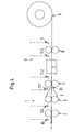
- FIG. 1 shows very schematically a spinning station of an exemplary embodiment of the spinning machine according to the invention.
- the spinning station has its own drafting device 1 (refining agent 1) as an internal spinning station with, for example, three cylinder pairs (inlet cylinder 2, middle cylinder 3 with straps 4 and outlet cylinder 5).
- the spinning station has a yarn-forming means 6, which for example consists essentially of a nozzle arrangement 7 and a pair of draw-off cylinders 8 for an air spinning process, and a yarn winding device 9.
- a first mass sensor 10 is provided upstream of the inlet cylinders 2 of the drafting device 1, which detects the fiber mass of the longitudinal fiber structure supplied to the drafting device 1.
- a second mass sensor (so-called yarn cleaner) is provided between the draw-off cylinder pair 8 and the yarn package 9, which detects the fiber mass of the yarn produced.
- the measurement data generated by the sensors 10 and 11 are fed to a control and monitoring unit 12.
- Inlet cylinder 2 and center cylinder 3 of the drafting system 1 are from a first Motor M.1 driven such that the longitudinal fiber structure between them Cylinder pairs experiences a constant advance.
- the speed of the engine M.1 is variable and is detected by a speed sensor Z.1.
- the engine M.1 is by means of Control data from the control and monitoring unit 12 based on the measurement data of Sensors 10 and 11 are generated, controlled.
- Outlet cylinder 5 of the drafting device 1 and take-off cylinder 8 of the yarn forming means 6 are operated by a further motor M.2 driven such that their peripheral speeds are one for the present Have a suitable yarn formation ratio (spinning delay).
- the speed of this other motor M.2 is detected by the speed sensor Z.2 and with suitable means kept constant.
- the stretching arrangement according to FIG. 1 corresponds essentially to an arrangement such as it is known per se from regulating drafting systems.
- the control and monitoring unit 12 processes the measurement data of the in a manner known per se from regulating drafting systems Sensors 10 and 11 to control signals based on the speed of the first motor M.1 is regulated. This will cause a suitable delay due to the Sensor 10 compensated for irregularities in the fiber mass Variation of the inlet speed (inlet cylinder) and variation of the draft between center cylinders 3 and outlet cylinders 5 (variable draft 20). With This control can be used to correct short-wave irregularities in particular be evened out. Irregularities in fiber mass from downstream sensor 11 on the finished yarn are detected in processed in the same way, which is a regulation that can not even out short-wave irregularities.
- the spinning station shown in FIG. 1 thus has a controlled in a known manner or regulated drafting system, the infeed speed being varied and the The outlet speed is constant, that is, the yarn formation with constant Delivery speed can be operated.
- the outlet speed is constant, that is, the yarn formation with constant Delivery speed can be operated.
- a spinning machine therefore has a large number (for example two hundred) spinning stations, all of which are equipped, such as those in the Figure 1 shown spinning station.
- the M.2 can be connected to the other motor All or a plurality of the spinning stations can be coupled and also the Control and monitoring unit 12 can be the entirety of the spinning stations or one Serve majority of them. At least those are assigned to each spinning station individually Pairs of inlet cylinders 2 and middle cylinders 3 of the drafting system, the sensors 10 and 11 and the first motor M.1 or a stepless replacement for this motor controllable gear between a central drive and each spinning station.
- the fiber longitudinal structures from the spinning positions Supply containers fed.
- a direct and continuous feed for example from a card or from a draw frame is only possible if between the Spinning station and the upstream device a buffer with a sufficiently large Buffer capacity is arranged, with which buffer variations in the Infeed speed can be bridged into the drafting system without that too the upstream device must be controlled accordingly.
- Such a Buffer can simply be designed as a free sag of the longitudinal fiber structure, which sag is monitored by sensors.
- the spinning station When exceeding a lower or upper limit of the buffer capacity, the spinning station is stopped or a Upstream device (card, drafting system) controlled accordingly, so that Delivery speed to the fill level of the buffer and / or to the Infeed speed in the spinning unit internal drafting system is adjusted.
- a Upstream device card, drafting system
- a stretching controlled internally according to FIG. 1 and constant Yarn formation is particularly applicable for spinning processes for which a change the delivery speed of the yarn formation a change in the yarn properties would require or for which a relatively rapid change in delivery speed yarn formation is not possible for mechanical reasons.
- Such spinning processes are, for various reasons, as already mentioned above, for example Ring spinning process, friction spinning process, pot spinning process, Bell spinning and open-end rotor spinning.
- FIG. 2 again shows a spinning station with a spreader-internal drafting unit 1 and yarn-forming means 6 for a spinning machine according to the invention, as shown in FIG. 1.
- the first motor M.1 is operated at a constant speed and the further motor M.2 is controlled accordingly.
- irregularities with regard to fiber mass which are detected by sensors 10 and 11, are compensated for by varying the outlet speed (outlet cylinder 5) from the drafting system, which causes corresponding variations in the delivery speeds of yarn forming agent 6.
- the speeds of the take-off cylinders 8 (coupled to the outlet cylinders 5 for constant spinning according to FIG. 2) and the winding 9, as well as any yarn formation parameters (fluid supply to the spinneret), must be variable and controllable by control signals generated by the control and monitoring unit 12. as indicated by corresponding arrows in FIG. 2.
- a control / regulation of the spinning positions of an inventive Spinning machine with spinning stations according to Figure 2 is particularly suitable for one direct and continuous feeding of fiber longitudinal structures to the spinning stations and for Spinning process, the delivery speed of which does not affect the Yarn properties are variable over a relatively wide range.
- Such spinning processes are, as already mentioned above, in particular air spinning processes. Since the Infeed speed to the spinning unit-internal drafting system is constant buffering before this entry or at least to a large buffer capacity to be dispensed with.
- FIG. 3 shows a spinning station for a spinning machine according to the invention, in which spinning station the control / regulation according to FIGS. 1 and 2 are essentially combined. While the motors M.1 and M.2 have variable speeds and are controlled by the control and monitoring unit 12, only the middle cylinder pair 3 is operated by a third motor M.3 at a constant speed. This results in two places of variable delay 20 and 20 '. For such control / regulation of the spinning stations, limit values must be specified for the first variable warping, the second variable warping, the spinning speed, further spinning parameters and, if appropriate, for buffer capacities upstream of the drafting unit 1. The operation of each spinning station must be kept or set within the specified limits if it is not possible to operate without crossing borders.
- the control unit can also control the delivery speed of a device (card or drafting device) upstream of the spinning machine, which supplies several spinning stations directly and continuously with fiber material, in such a way that the capacity is optimally utilized, i.e. the upstream device and the spinning stations are operated in this way ( or not operated for spinning positions) that the output of yarn is maximum.
- a device card or drafting device
- the control unit can also control the delivery speed of a device (card or drafting device) upstream of the spinning machine, which supplies several spinning stations directly and continuously with fiber material, in such a way that the capacity is optimally utilized, i.e. the upstream device and the spinning stations are operated in this way ( or not operated for spinning positions) that the output of yarn is maximum.
- the spinning delay (variable delay 20 ) be included in the control.
- the spinning station according to FIG. 3 is also suitable for a performance variation of the Spinning station as a whole to adapt this performance to the delivery performance of a upstream device providing the longitudinal fiber structure to be spun or to spin on.
- FIG. 4 again shows a spinning station with a spreader-internal drafting system 1 for a spinning machine according to the invention, as is already shown in FIGS. 1 to 3.
- the sensors 10 for a control and 11 for a long-wave control there are further possible sensor positions 10.1 (between the inlet cylinder 2 and the center cylinder 3 for a control), 11.1 (between the center cylinder 2 and the outlet cylinder 5, immediately after the variable draft 20, for a relatively short-wave control) and 11.2 and 11.3 (between discharge cylinder 5 and nozzle arrangement 7 and between nozzle arrangement 7 and discharge cylinder 8, both for regulation).
- the measurement data from sensor positions 10 and 10.1 upstream of the variable draft 20
- the measurement data from sensor positions 11, 11.1, 11.2 and 11.3 are used for draft regulation.
- each spinning position of the spinning machine according to the invention Arrange mass sensor, as already mentioned in connection with Figure 1 advantageously two, one upstream and one downstream of the Variable delay 20 is to be arranged.
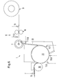
- FIG. 5 shows another exemplary spinning station for a spinning machine according to the invention.
- This spinning station has a feed cylinder 30, a dissolving roller 31 and a fiber guiding channel 32 for dissolving the longitudinal fiber structure (refining means 1), the fibers being removed by the fiber guiding channel 32 after the dissolution at a separation point 33 from the dissolving roller 30 and yarn formation, for example are supplied by rotor open-end spinning (rotor arrangement 7 ').
- the device parts downstream of the rotor arrangement 7 ′ are essentially the same as for the spinning station according to FIGS. 1 to 4.
- the mass sensor 10 detects the fiber mass of the feed cylinder 30 Fiber material
- the mass sensor 11 detects the fiber mass of the finished yarn the spool 9.
- the feed cylinder 30 is variable by a first motor M.1 Which motor is driven by the speed of the control and monitoring unit 12 generated control signals is driven. Opening roller 31 and take-off cylinder 8 are driven by a second motor M.2 at a constant speed (constant spinning delay).
- the control / regulation of the spinning station corresponds to essentially that described in connection with FIG. 1 Control / regulation, that means that the infeed speed to the Refinement 1 is regulated and the delivery speed of the Yarn forming agent 6 remains substantially constant.
- the place of the variable Delay 20 is located between the feed roller 30 and the opening roller 31.
- the spinning station arrangement is suitable especially for yarn formation by a rotor open-end spinning process in which Variations in take-off speed changes in thread tension and thereby in the yarn properties, such that the delivery speed of the Yarn formation for a high yarn regularity is to be kept essentially constant.
- the spinning position shown in FIG. 5 can, however, be used accordingly suitable spinning processes also controlled / regulated analogously to Figures 2 and 3 in such a way that not only the dissolving step preceding the yarn formation is varied, but also the yarn formation itself or both.
- FIG. 6 shows, similarly to FIG. 4, further possible sensor positions 11.5 to 11.8 (in the area of the opening roller 31 and the fiber guide channel 32 for a relatively short-wave control) and 11.9 between the rotor arrangement 7 and take-off cylinders 8 for a long-wave control).
Landscapes
- Engineering & Computer Science (AREA)
- Mechanical Engineering (AREA)
- Textile Engineering (AREA)
- Spinning Or Twisting Of Yarns (AREA)
- Spinning Methods And Devices For Manufacturing Artificial Fibers (AREA)
Applications Claiming Priority (2)
| Application Number | Priority Date | Filing Date | Title |
|---|---|---|---|
| CH21742000 | 2000-11-08 | ||
| CH21742000 | 2000-11-08 |
Publications (2)
| Publication Number | Publication Date |
|---|---|
| EP1205588A1 true EP1205588A1 (fr) | 2002-05-15 |
| EP1205588B1 EP1205588B1 (fr) | 2004-12-15 |
Family
ID=4567839
Family Applications (1)
| Application Number | Title | Priority Date | Filing Date |
|---|---|---|---|
| EP01124919A Revoked EP1205588B1 (fr) | 2000-11-08 | 2001-10-19 | Dispositif de commande pour des postes de filature d'un métier à filer |
Country Status (4)
| Country | Link |
|---|---|
| US (1) | US6679043B2 (fr) |
| EP (1) | EP1205588B1 (fr) |
| AT (1) | ATE284987T1 (fr) |
| DE (1) | DE50104822D1 (fr) |
Cited By (4)
| Publication number | Priority date | Publication date | Assignee | Title |
|---|---|---|---|---|
| EP1398402A2 (fr) * | 2002-09-16 | 2004-03-17 | Maschinenfabrik Rieter Ag | Métiers à filer à vortex d'air avec des moteurs à réluctance |
| WO2006042686A1 (fr) * | 2004-10-15 | 2006-04-27 | Maschinenfabrik Rieter Ag | Procede pour preparer un processus de rattachement sur un dispositif de filage a buse d'air |
| WO2006048186A3 (fr) * | 2004-11-02 | 2006-10-12 | Rieter Ag Maschf | Procede pour optimiser le rendement de la production d'un metier a filer |
| EP1219737B2 (fr) † | 2000-12-22 | 2012-01-18 | Maschinenfabrik Rieter Ag | Procédé pour rabouter ou mettre en place un fil crée dans une unité de filature, ladite unité étant equipée pour la mise en oeuvre du procédé |
Families Citing this family (5)
| Publication number | Priority date | Publication date | Assignee | Title |
|---|---|---|---|---|
| EP1375709B1 (fr) | 2002-06-21 | 2014-08-06 | Maschinenfabrik Rieter Ag | Procédé de rattache pour, ou rattachement dans, des postes de filature des métiers à filer à vortex d'air |
| US7841162B2 (en) * | 2003-07-10 | 2010-11-30 | Return Textiles, Llc | Yarns, particularly yarns incorporating recycled material, and methods of making them |
| EP1522614A1 (fr) * | 2003-10-06 | 2005-04-13 | Schärer Schweiter Mettler AG | Dispositif pour produire des filés de fibres synthétiques |
| CZ306608B6 (cs) * | 2004-10-22 | 2017-03-29 | VĂšTS, a.s. | Způsob měření tažnosti přízí a podobných délkových útvarů a zařízení k provádění způsobu |
| ITTO20110693A1 (it) * | 2010-08-11 | 2011-10-27 | Rieter Ingolstadt Gmbh | Meccanismo di stiratura di una macchina tessile nonche' procedimento per il suo funzionamento |
Citations (7)
| Publication number | Priority date | Publication date | Assignee | Title |
|---|---|---|---|---|
| US4506414A (en) * | 1982-02-18 | 1985-03-26 | Zinser Textilmaschinen Gmbh | Yarn-drafting apparatus |
| DE3932614A1 (de) * | 1988-09-29 | 1990-04-05 | Murata Machinery Ltd | Streckwerk |
| EP0365931A1 (fr) * | 1988-10-26 | 1990-05-02 | Schubert & Salzer Maschinenfabrik Aktiengesellschaft | Procédé et dispositif pour commander un métier à filer à jet d'air |
| DE4140669A1 (de) * | 1991-12-10 | 1993-06-17 | Fritz Stahlecker | Spinnmaschine |
| US5481860A (en) * | 1991-07-23 | 1996-01-09 | Stahlecker; Fritz | Spinning machine having a plurality of spinning stations with independently controllable delivery rollers |
| DE19542599A1 (de) * | 1995-11-15 | 1997-05-22 | Schlafhorst & Co W | Transportsystem für Faserband |
| US6052984A (en) * | 1996-10-02 | 2000-04-25 | Rieter Ingolstadt Spinnereimaschinenbau Ag | Textile drafting machine with upstream dirt separating device |
Family Cites Families (14)
| Publication number | Priority date | Publication date | Assignee | Title |
|---|---|---|---|---|
| CH668781A5 (de) | 1984-09-25 | 1989-01-31 | Zellweger Uster Ag | Verfahren und vorrichtung zur optimierung des streckprozesses bei regulierstrecken der textilindustrie. |
| DE3703450A1 (de) | 1986-05-24 | 1987-11-26 | Truetzschler & Co | Verfahren und vorrichtung zur vergleichmaessigung des faserbandes bei einer karde |
| DE3635341A1 (de) | 1986-10-17 | 1988-04-28 | Zinser Textilmaschinen Gmbh | Vorrichtung zur regulierung des verzugs eines faserbands bei einer textilmaschine |
| DE3703449C2 (de) | 1987-02-05 | 1998-07-23 | Truetzschler Gmbh & Co Kg | Vorrichtung zum Ermitteln von Fremdkörpern, wie Metallteilen, Drähten o. dgl. innerhalb von bzw. zwischen Textilfaserflocken |
| IN171021B (fr) | 1987-04-27 | 1992-07-04 | Rieter Ag Maschf | |
| JPH0720800B2 (ja) * | 1988-03-01 | 1995-03-08 | 村田機械株式会社 | 紡績工場における品質管理システム |
| DE3815200C2 (de) | 1988-05-04 | 1998-01-29 | Truetzschler Gmbh & Co Kg | Verfahren und Vorrichtung zur Überwachung des Vergleichmäßigens mindestens eines Faserverbandes in einem Regulierstreckwerk |
| US5272790A (en) * | 1989-07-26 | 1993-12-28 | Maschinenfabrik Rieter Ag | Maintaining a predetermined quality of sliver in a card and/or drawframe |
| CH685506A5 (de) * | 1993-06-23 | 1995-07-31 | Zellweger Uster Ag | Vorrichtung zur Messung der Masse oder des Substanzquerschnitts von Faserbändern und Verwendung der Vorrichtung. |
| JP3271397B2 (ja) | 1993-10-25 | 2002-04-02 | 豊和工業株式会社 | 紡機におけるスライバ斑制御装置 |
| DE4424091A1 (de) * | 1994-07-12 | 1996-01-18 | Kaendler Maschinenbau Gmbh | Verfahren zum Regulieren eines Streckwerkes, insbesondere an Karden und Reguliervorrichtung |
| WO1999011847A1 (fr) | 1997-09-01 | 1999-03-11 | Maschinenfabrik Rieter Ag | Banc d'etirage regule |
| US6499194B1 (en) | 1998-06-12 | 2002-12-31 | Maschinenfabrik Rieter Ag | Adjusting drawframe |
| EP1332248B9 (fr) | 2000-09-22 | 2016-07-13 | Maschinenfabrik Rieter Ag | Dispositif de filage |
-
2001
- 2001-10-19 EP EP01124919A patent/EP1205588B1/fr not_active Revoked
- 2001-10-19 AT AT01124919T patent/ATE284987T1/de not_active IP Right Cessation
- 2001-10-19 DE DE50104822T patent/DE50104822D1/de not_active Revoked
- 2001-11-08 US US10/008,611 patent/US6679043B2/en not_active Expired - Fee Related
Patent Citations (7)
| Publication number | Priority date | Publication date | Assignee | Title |
|---|---|---|---|---|
| US4506414A (en) * | 1982-02-18 | 1985-03-26 | Zinser Textilmaschinen Gmbh | Yarn-drafting apparatus |
| DE3932614A1 (de) * | 1988-09-29 | 1990-04-05 | Murata Machinery Ltd | Streckwerk |
| EP0365931A1 (fr) * | 1988-10-26 | 1990-05-02 | Schubert & Salzer Maschinenfabrik Aktiengesellschaft | Procédé et dispositif pour commander un métier à filer à jet d'air |
| US5481860A (en) * | 1991-07-23 | 1996-01-09 | Stahlecker; Fritz | Spinning machine having a plurality of spinning stations with independently controllable delivery rollers |
| DE4140669A1 (de) * | 1991-12-10 | 1993-06-17 | Fritz Stahlecker | Spinnmaschine |
| DE19542599A1 (de) * | 1995-11-15 | 1997-05-22 | Schlafhorst & Co W | Transportsystem für Faserband |
| US6052984A (en) * | 1996-10-02 | 2000-04-25 | Rieter Ingolstadt Spinnereimaschinenbau Ag | Textile drafting machine with upstream dirt separating device |
Cited By (6)
| Publication number | Priority date | Publication date | Assignee | Title |
|---|---|---|---|---|
| EP1219737B2 (fr) † | 2000-12-22 | 2012-01-18 | Maschinenfabrik Rieter Ag | Procédé pour rabouter ou mettre en place un fil crée dans une unité de filature, ladite unité étant equipée pour la mise en oeuvre du procédé |
| EP1398402A2 (fr) * | 2002-09-16 | 2004-03-17 | Maschinenfabrik Rieter Ag | Métiers à filer à vortex d'air avec des moteurs à réluctance |
| EP1398402A3 (fr) * | 2002-09-16 | 2004-09-01 | Maschinenfabrik Rieter Ag | Métiers à filer à vortex d'air avec des moteurs à réluctance |
| WO2006042686A1 (fr) * | 2004-10-15 | 2006-04-27 | Maschinenfabrik Rieter Ag | Procede pour preparer un processus de rattachement sur un dispositif de filage a buse d'air |
| WO2006048186A3 (fr) * | 2004-11-02 | 2006-10-12 | Rieter Ag Maschf | Procede pour optimiser le rendement de la production d'un metier a filer |
| JP2008519168A (ja) * | 2004-11-02 | 2008-06-05 | マシーネンファブリク リーター アクチェンゲゼルシャフト | 紡績機の生産能率を最適化する方法 |
Also Published As
| Publication number | Publication date |
|---|---|
| DE50104822D1 (de) | 2005-01-20 |
| US20020124545A1 (en) | 2002-09-12 |
| US6679043B2 (en) | 2004-01-20 |
| EP1205588B1 (fr) | 2004-12-15 |
| ATE284987T1 (de) | 2005-01-15 |
Similar Documents
| Publication | Publication Date | Title |
|---|---|---|
| EP1817448B1 (fr) | Procede pour optimiser le rendement de la production d'un metier a filer | |
| DE102011053396B3 (de) | Vorrichtung und Verfahren zur Herstellung von Maschenware | |
| DE19815053B4 (de) | Verfahren zum Herstellen eines Scheinzwirnes und Spinnmaschine hierfür | |
| DE3842120C2 (de) | Verfahren und Vorrichtung zum Herstellen doublierter Fäden | |
| EP2112258A2 (fr) | Dispositif et procédé d'enroulement d'une mèche sur une bobine | |
| EP1205588B1 (fr) | Dispositif de commande pour des postes de filature d'un métier à filer | |
| EP2740821B1 (fr) | Dispositif de filage pneumatique | |
| DE3926227C2 (fr) | ||
| DE10236450A1 (de) | Spinnmaschine mit einem Mehrstufen-Verdichtungs-Streckwerk | |
| WO2008017340A1 (fr) | Dispositif de fabrication d'un article maille | |
| EP1071837A1 (fr) | Procede et dispositif de filage avec suppression du ballon de fil | |
| DE102005009731A1 (de) | Flyerloses Spinnverfahren sowie Vorrichtung mit einem Streckwerk | |
| EP1573098B1 (fr) | Dispositif pour fabriquer une fibre filee | |
| EP0578955A1 (fr) | Procédé de préparation d'un enroulement de nappe | |
| EP2980284B1 (fr) | Procede de fabrication d'un fil produit par jet d'air | |
| DE3249876C2 (fr) | ||
| EP0489128A1 (fr) | Systeme de commande de processus pour une filature - signaux de commande en provenance de la station precedente | |
| DE3822294A1 (de) | Verfahren zum wiederanspinnen eines doppelfadens an einem spinnaggregat einer spinnmaschine | |
| EP3794169A1 (fr) | Procédé de détermination de la garniture de tambour au niveau d'une karde et karde équipée d'une commande associée | |
| DE4119877A1 (de) | Regelung der kaemmaschine | |
| DE102017102623A1 (de) | Verfahren und Anlage zur Bearbeitung von Fasern | |
| DE102016110897A1 (de) | Spinnereivorbereitungsmaschine in Form einer Strecke sowie Verfahren zum Betreiben einer solchen | |
| DE3719281A1 (de) | Verfahren und vorrichtung zum erzeugen von jeweils zwei fadenkomponenten | |
| WO2023217322A1 (fr) | Banc d'étirage, machine de traitement de fibres à banc d'étirage et procédé pour faire fonctionner un banc d'étirage | |
| WO2021122669A1 (fr) | Procédé permettant d'agencer un brin de fibres sur un dispositif de filage d'un poste de filage |
Legal Events
| Date | Code | Title | Description |
|---|---|---|---|
| PUAI | Public reference made under article 153(3) epc to a published international application that has entered the european phase |
Free format text: ORIGINAL CODE: 0009012 |
|
| AK | Designated contracting states |
Kind code of ref document: A1 Designated state(s): AT BE CH CY DE DK ES FI FR GB GR IE IT LI LU MC NL PT SE TR |
|
| AX | Request for extension of the european patent |
Free format text: AL;LT;LV;MK;RO;SI |
|
| 17P | Request for examination filed |
Effective date: 20020624 |
|
| AKX | Designation fees paid |
Designated state(s): AT BE CH CY DE DK ES FI FR GB GR IE IT LI LU MC NL PT SE TR |
|
| 17Q | First examination report despatched |
Effective date: 20030520 |
|
| GRAP | Despatch of communication of intention to grant a patent |
Free format text: ORIGINAL CODE: EPIDOSNIGR1 |
|
| GRAS | Grant fee paid |
Free format text: ORIGINAL CODE: EPIDOSNIGR3 |
|
| GRAA | (expected) grant |
Free format text: ORIGINAL CODE: 0009210 |
|
| AK | Designated contracting states |
Kind code of ref document: B1 Designated state(s): AT BE CH CY DE DK ES FI FR GB GR IE IT LI LU MC NL PT SE TR |
|
| PG25 | Lapsed in a contracting state [announced via postgrant information from national office to epo] |
Ref country code: IE Free format text: LAPSE BECAUSE OF FAILURE TO SUBMIT A TRANSLATION OF THE DESCRIPTION OR TO PAY THE FEE WITHIN THE PRESCRIBED TIME-LIMIT Effective date: 20041215 Ref country code: FI Free format text: LAPSE BECAUSE OF FAILURE TO SUBMIT A TRANSLATION OF THE DESCRIPTION OR TO PAY THE FEE WITHIN THE PRESCRIBED TIME-LIMIT Effective date: 20041215 Ref country code: NL Free format text: LAPSE BECAUSE OF FAILURE TO SUBMIT A TRANSLATION OF THE DESCRIPTION OR TO PAY THE FEE WITHIN THE PRESCRIBED TIME-LIMIT Effective date: 20041215 Ref country code: GB Free format text: LAPSE BECAUSE OF FAILURE TO SUBMIT A TRANSLATION OF THE DESCRIPTION OR TO PAY THE FEE WITHIN THE PRESCRIBED TIME-LIMIT Effective date: 20041215 |
|
| REG | Reference to a national code |
Ref country code: CH Ref legal event code: EP Ref country code: GB Ref legal event code: FG4D Free format text: NOT ENGLISH |
|
| REG | Reference to a national code |
Ref country code: IE Ref legal event code: FG4D Free format text: GERMAN |
|
| REF | Corresponds to: |
Ref document number: 50104822 Country of ref document: DE Date of ref document: 20050120 Kind code of ref document: P |
|
| PG25 | Lapsed in a contracting state [announced via postgrant information from national office to epo] |
Ref country code: SE Free format text: LAPSE BECAUSE OF FAILURE TO SUBMIT A TRANSLATION OF THE DESCRIPTION OR TO PAY THE FEE WITHIN THE PRESCRIBED TIME-LIMIT Effective date: 20050315 Ref country code: GR Free format text: LAPSE BECAUSE OF FAILURE TO SUBMIT A TRANSLATION OF THE DESCRIPTION OR TO PAY THE FEE WITHIN THE PRESCRIBED TIME-LIMIT Effective date: 20050315 Ref country code: DK Free format text: LAPSE BECAUSE OF FAILURE TO SUBMIT A TRANSLATION OF THE DESCRIPTION OR TO PAY THE FEE WITHIN THE PRESCRIBED TIME-LIMIT Effective date: 20050315 |
|
| PG25 | Lapsed in a contracting state [announced via postgrant information from national office to epo] |
Ref country code: ES Free format text: LAPSE BECAUSE OF FAILURE TO SUBMIT A TRANSLATION OF THE DESCRIPTION OR TO PAY THE FEE WITHIN THE PRESCRIBED TIME-LIMIT Effective date: 20050326 |
|
| NLV1 | Nl: lapsed or annulled due to failure to fulfill the requirements of art. 29p and 29m of the patents act | ||
| GBV | Gb: ep patent (uk) treated as always having been void in accordance with gb section 77(7)/1977 [no translation filed] |
Effective date: 20041215 |
|
| REG | Reference to a national code |
Ref country code: IE Ref legal event code: FD4D |
|
| PLBI | Opposition filed |
Free format text: ORIGINAL CODE: 0009260 |
|
| PG25 | Lapsed in a contracting state [announced via postgrant information from national office to epo] |
Ref country code: CY Free format text: LAPSE BECAUSE OF FAILURE TO SUBMIT A TRANSLATION OF THE DESCRIPTION OR TO PAY THE FEE WITHIN THE PRESCRIBED TIME-LIMIT Effective date: 20051019 Ref country code: AT Free format text: LAPSE BECAUSE OF NON-PAYMENT OF DUE FEES Effective date: 20051019 |
|
| PLAX | Notice of opposition and request to file observation + time limit sent |
Free format text: ORIGINAL CODE: EPIDOSNOBS2 |
|
| PG25 | Lapsed in a contracting state [announced via postgrant information from national office to epo] |
Ref country code: LU Free format text: LAPSE BECAUSE OF NON-PAYMENT OF DUE FEES Effective date: 20051031 Ref country code: MC Free format text: LAPSE BECAUSE OF NON-PAYMENT OF DUE FEES Effective date: 20051031 Ref country code: BE Free format text: LAPSE BECAUSE OF NON-PAYMENT OF DUE FEES Effective date: 20051031 |
|
| 26 | Opposition filed |
Opponent name: SAURER GMBH & CO. KG Effective date: 20050913 |
|
| ET | Fr: translation filed | ||
| PLBB | Reply of patent proprietor to notice(s) of opposition received |
Free format text: ORIGINAL CODE: EPIDOSNOBS3 |
|
| APBP | Date of receipt of notice of appeal recorded |
Free format text: ORIGINAL CODE: EPIDOSNNOA2O |
|
| APAH | Appeal reference modified |
Free format text: ORIGINAL CODE: EPIDOSCREFNO |
|
| PLAB | Opposition data, opponent's data or that of the opponent's representative modified |
Free format text: ORIGINAL CODE: 0009299OPPO |
|
| R26 | Opposition filed (corrected) |
Opponent name: OERLIKON TEXTILE GMBH & CO. KG Effective date: 20050913 |
|
| BERE | Be: lapsed |
Owner name: MASCHINENFABRIK *RIETER A.G. Effective date: 20051031 |
|
| PG25 | Lapsed in a contracting state [announced via postgrant information from national office to epo] |
Ref country code: PT Free format text: LAPSE BECAUSE OF NON-PAYMENT OF DUE FEES Effective date: 20050515 |
|
| PGFP | Annual fee paid to national office [announced via postgrant information from national office to epo] |
Ref country code: CH Payment date: 20071015 Year of fee payment: 7 |
|
| PGFP | Annual fee paid to national office [announced via postgrant information from national office to epo] |
Ref country code: FR Payment date: 20071016 Year of fee payment: 7 |
|
| APBU | Appeal procedure closed |
Free format text: ORIGINAL CODE: EPIDOSNNOA9O |
|
| PGFP | Annual fee paid to national office [announced via postgrant information from national office to epo] |
Ref country code: DE Payment date: 20081022 Year of fee payment: 8 Ref country code: TR Payment date: 20080919 Year of fee payment: 8 |
|
| RDAF | Communication despatched that patent is revoked |
Free format text: ORIGINAL CODE: EPIDOSNREV1 |
|
| RDAG | Patent revoked |
Free format text: ORIGINAL CODE: 0009271 |
|
| STAA | Information on the status of an ep patent application or granted ep patent |
Free format text: STATUS: PATENT REVOKED |
|
| REG | Reference to a national code |
Ref country code: CH Ref legal event code: PL |
|
| 27W | Patent revoked |
Effective date: 20081002 |
|
| PGFP | Annual fee paid to national office [announced via postgrant information from national office to epo] |
Ref country code: IT Payment date: 20081024 Year of fee payment: 8 |