EP1203632A2 - Machine-outil avec système de commande de la position de l'outil - Google Patents
Machine-outil avec système de commande de la position de l'outil Download PDFInfo
- Publication number
- EP1203632A2 EP1203632A2 EP01125140A EP01125140A EP1203632A2 EP 1203632 A2 EP1203632 A2 EP 1203632A2 EP 01125140 A EP01125140 A EP 01125140A EP 01125140 A EP01125140 A EP 01125140A EP 1203632 A2 EP1203632 A2 EP 1203632A2
- Authority
- EP
- European Patent Office
- Prior art keywords
- origin
- work
- machine
- tool
- control unit
- Prior art date
- Legal status (The legal status is an assumption and is not a legal conclusion. Google has not performed a legal analysis and makes no representation as to the accuracy of the status listed.)
- Granted
Links
- 238000000034 method Methods 0.000 claims abstract description 66
- 238000005259 measurement Methods 0.000 claims abstract description 34
- 238000006073 displacement reaction Methods 0.000 description 5
- 238000001514 detection method Methods 0.000 description 3
- 238000010586 diagram Methods 0.000 description 3
- 230000002542 deteriorative effect Effects 0.000 description 2
- 238000004904 shortening Methods 0.000 description 2
Images


Classifications
-
- B—PERFORMING OPERATIONS; TRANSPORTING
- B23—MACHINE TOOLS; METAL-WORKING NOT OTHERWISE PROVIDED FOR
- B23Q—DETAILS, COMPONENTS, OR ACCESSORIES FOR MACHINE TOOLS, e.g. ARRANGEMENTS FOR COPYING OR CONTROLLING; MACHINE TOOLS IN GENERAL CHARACTERISED BY THE CONSTRUCTION OF PARTICULAR DETAILS OR COMPONENTS; COMBINATIONS OR ASSOCIATIONS OF METAL-WORKING MACHINES, NOT DIRECTED TO A PARTICULAR RESULT
- B23Q15/00—Automatic control or regulation of feed movement, cutting velocity or position of tool or work
- B23Q15/007—Automatic control or regulation of feed movement, cutting velocity or position of tool or work while the tool acts upon the workpiece
-
- B—PERFORMING OPERATIONS; TRANSPORTING
- B23—MACHINE TOOLS; METAL-WORKING NOT OTHERWISE PROVIDED FOR
- B23Q—DETAILS, COMPONENTS, OR ACCESSORIES FOR MACHINE TOOLS, e.g. ARRANGEMENTS FOR COPYING OR CONTROLLING; MACHINE TOOLS IN GENERAL CHARACTERISED BY THE CONSTRUCTION OF PARTICULAR DETAILS OR COMPONENTS; COMBINATIONS OR ASSOCIATIONS OF METAL-WORKING MACHINES, NOT DIRECTED TO A PARTICULAR RESULT
- B23Q17/00—Arrangements for observing, indicating or measuring on machine tools
- B23Q17/22—Arrangements for observing, indicating or measuring on machine tools for indicating or measuring existing or desired position of tool or work
- B23Q17/2233—Arrangements for observing, indicating or measuring on machine tools for indicating or measuring existing or desired position of tool or work for adjusting the tool relative to the workpiece
- B23Q17/2266—Arrangements for observing, indicating or measuring on machine tools for indicating or measuring existing or desired position of tool or work for adjusting the tool relative to the workpiece of a tool relative to a workpiece-axis
-
- Y—GENERAL TAGGING OF NEW TECHNOLOGICAL DEVELOPMENTS; GENERAL TAGGING OF CROSS-SECTIONAL TECHNOLOGIES SPANNING OVER SEVERAL SECTIONS OF THE IPC; TECHNICAL SUBJECTS COVERED BY FORMER USPC CROSS-REFERENCE ART COLLECTIONS [XRACs] AND DIGESTS
- Y10—TECHNICAL SUBJECTS COVERED BY FORMER USPC
- Y10T—TECHNICAL SUBJECTS COVERED BY FORMER US CLASSIFICATION
- Y10T409/00—Gear cutting, milling, or planing
- Y10T409/30—Milling
- Y10T409/304536—Milling including means to infeed work to cutter
- Y10T409/304648—Milling including means to infeed work to cutter with control means energized in response to activator stimulated by condition sensor
-
- Y—GENERAL TAGGING OF NEW TECHNOLOGICAL DEVELOPMENTS; GENERAL TAGGING OF CROSS-SECTIONAL TECHNOLOGIES SPANNING OVER SEVERAL SECTIONS OF THE IPC; TECHNICAL SUBJECTS COVERED BY FORMER USPC CROSS-REFERENCE ART COLLECTIONS [XRACs] AND DIGESTS
- Y10—TECHNICAL SUBJECTS COVERED BY FORMER USPC
- Y10T—TECHNICAL SUBJECTS COVERED BY FORMER US CLASSIFICATION
- Y10T82/00—Turning
- Y10T82/25—Lathe
- Y10T82/2502—Lathe with program control
-
- Y—GENERAL TAGGING OF NEW TECHNOLOGICAL DEVELOPMENTS; GENERAL TAGGING OF CROSS-SECTIONAL TECHNOLOGIES SPANNING OVER SEVERAL SECTIONS OF THE IPC; TECHNICAL SUBJECTS COVERED BY FORMER USPC CROSS-REFERENCE ART COLLECTIONS [XRACs] AND DIGESTS
- Y10—TECHNICAL SUBJECTS COVERED BY FORMER USPC
- Y10T—TECHNICAL SUBJECTS COVERED BY FORMER US CLASSIFICATION
- Y10T82/00—Turning
- Y10T82/25—Lathe
- Y10T82/2531—Carriage feed
- Y10T82/2533—Control
Definitions
- the present invention relates to a machine tool like a lathe and a grinding machine and so on.
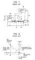
- a mechanical origin (0 M ) in the control unit 50 is set to position the location where the tool base 51 is the most far from a headstock 54.
- Figure 8 shows the mechanical origin (0 M ) that is the origin in the coordinate of the feedback signal F/B by the encoder 53.
- a process origin (0 w ) as shown in Figure 8 is the center of a work (W) which is gripped by a spindle 55 ( Figure 7) and is positioned far from the mechanical origin (0 M ) that is the origin of the feedback signal F/B, so that the substantial margin of error comes out even if the feedback control is carried out, if there are the thermal expansion of the ball screw 56 and the mechanical deformation.
- the high accuracy amendment is difficult though the thermal expansion is amended, so that there is a limit to improve the process accuracy.
- the closed loop control is also adopted by providing a linear sensor 57 as shown in the dash-dot line in Figure 7.
- the linear sensor 57 is attached along the slide surface of the machine, for example a guide of the tool base (not shown in the drawings) in a bed 58. According to this, the position of the tool base 51 can be detected directly without acting on the thermal expansion of the ball screw 56.
- Figure 1 is a block diagram, showing the general structure of the machine tool in an embodiment of the present invention.
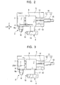
- Figure 2 is a top view of the machine part of the same machine tool.
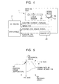
- Figure 3 is a top view of a variation of the machine part of the same machine tool.
- Figure 4 is an illustrative diagram of the feedback signal in the same machine tool.
- Figure 5 is an illustrative diagram, showing the working of the same machine tool.
- Figure 6 is a partially enlarged top view in the other embodiment of the present invention.
- Figure 7 is a front view according to a conventional machine tool.
- Figure 8 is an explanation drawing of the operation of the conventional machine tool.
- This machine tool is equipped with a support work means 3 which supports the work (W), a cutting means 4 which is movable to the work support means 3 in order to process the work (W) and a control unit 2 that the movement of the aforementioned cutting means 4 is controlled by the positional information based on a process origin (0w) that is the prescribed position of the work (W) supported by the work support means 3.
- the control unit 2 controls the movement of the cutting means 4 by the positional information based on the process origin (0w) that is the prescribed position of the work support means 3.
- the prescribed position of the work support means 3 is the center of a spindle 8 etc. which composes the work support means 3, for example.
- the above-mentioned positional information is the measured positional information for instance, and the information is used in a feedback control and so on in the control unit 2.
- the positional information based on the process origin (0w) like this, even if some displacement is generated to the machine itself by the heat displacement or the disturbance, the error which the positional information affects the process accuracy is only the machine displacement of a machine part 1 corresponded to the process measurement from the process origin (0w) to the work (W). Therefore, the process accuracy does not deteriorate even if the accuracy of the machine itself changes to some extent.
- a location measurement means 25 which measures the position of the moving direction of the aforementioned cutting means 4 based on the aforementioned process origin (0w) is provided, and the aforementioned positional information can be obtained from the location measurement means 25.
- a linear sensor or a laser-measuring machine can be used as the above-mentioned position measurement means 25.
- the aforementioned location measurement means 25 may measure only the moving range that the aforementioned cutting means 4 processes.
- the range that the measured positional information affects the process accuracy is only the moving range that the cutting means 4 processes, so that the process accuracy can be improved if the position measurement means 25 can measure this moving range.
- the high accuracy position measurement means is expensive, the cost can be reduced by shortening the means, only the length of the moving range that processes like this.
- the lower-accuracy measurement means can be used compared with the one for using the moving range to process, and the semi-closed loop control by encoders and the like which is attached on a servo motor 13 can be also used.
- This machine tool comprising a numerical control type lathe, is equipped with the machine part 1 and the control unit 2 which controls the machine part 1.
- the machine part 1 has the work support means 3 which supports the work (W) and the cutting means 4 which is movable to the work support means 3 in order to cut the work (W).
- the control unit 2 has the function to control the movement of the cutting means 4 by the measured positional information base on the process origin (0w) that is the prescribed position of the work support means 3.
- the work support means 3 comprises the spindle 8 supported by a headstock 7 on a bed 5 and a spindle chuck 8a installed on the spindle 8.
- the spindle 8 is driven by a spindle motor (not shown in the drawings) which is installed in the bed 5.
- the cutting means 4 comprises a feed bar 9 installed on the bed 5, a tool base 10 installed in the feed bar 9 and a movable drive means 11 of the feed bar 9.
- the feed bar 9 is installed on a guide 12 (see Figure 2) provided in the bed 5 such as to move to the orthogonal direction (X-axis direction) to the axis direction (Z-axis direction) of the spindle 8.
- the movable drive means 11 moves the feed bar 9 through a ball screw mechanism 14 by the rotation of a servomotor 13.
- the servomotor 13 has a rotary detector 15 like a pulse coder or a pulse generator.
- the tool base 10 comprises a turret, and a bite or a tool 16 like a rotating tool is installed on a plurality part of the contour.
- the turret tool base 10 is installed to be freely access to the Z-axis direction orthogonal to the moving direction (X-axis direction) to the feed bar 9 through a turret axis 17, and is installed to rotate freely.
- the feed bar 9 is loaded on a freely access drive means and an indexing rotary means of the tool base 10 (not shown in the drawings).
- the cutting means 4 is not confined to the turret type, and the tool 16 may be installed in the feed bar 9, omitting the tool base 10.
- the feed bar 9 can be the tool base.
- the control unit 2 comprising a numerical control unit, is the means to control the each part of the machine part 1, decoding a cutting program 20 by an operation control unit 21.
- the control unit 2 has the function of a programmable controller.
- the operation control unit 21 has the function to output a drive command to a servo controller 22 according to the movement command to the X-axis direction of the cutting program 20.
- the servo controller 22 feedback-controls the servomotor 13 according to the above-mentioned drive command. Only the position feedback, or the only position and the velocity feedback may be used in the feedback control by the servo controller 22, but the position, the velocity and the electric current feedback are carried out in this example (refer to Figure 4).
- the velocity feedback is carried out by using the speed detection signal of the rotary detector 15 which is made by the pulse generator installed on the servomotor 13.
- the electric current feedback is carried out by using the electric current value by an ammeter 24 provided with the power circuit of the servomotor 13.
- the position feedback by the servo controller 22 is carried out by switching a control by the position detection signal of the rotary detector 15 provided on the servomotor 13 and a position detection signal of the position measurement means 25 which the position of the feed bar 9 is detected directly.
- the position measurement means 25, comprising a linear sensor, has a scale part 25a and a reading unit 25b which reads the scale part 25a.
- the scale part 25a is installed on the work support means 3. To be more precise, the scale part 25a is installed on the headstock 7.
- the reading part 25b is installed on the cutting means 4.
- the reading unit 25b is installed on the feed bar 9.
- the reading part 25 outputs through a sensor interface 26.
- the scale 25a may be provided on the feed bar 9, and the reading part 25b may be installed on the headstock 7.
- the measurement origin position of the position measurement means 25 comprising a linear sensor is adjusted to the center of the cutting means 4, or the process origin (0 W ) that the spindle 8 rotates, to the X-axis direction that is the measurement direction.
- the origin of the scale part 25a is adjusted to the process origin (0w).
- the position measurement means 25 can only measure the moving range that the cutting means 4 processes.
- the moving range means the range from the process origin (0w) to the radius dimension of the maximum-diameter work (W) which the spindle 8 can support, or includes the slightly buffer distance to this range.
- the control unit 2 has an input switching means 23, and the input switching means 23 delivers the output to the servo controller 22 by switching the output of the position measurement means 25 and the position detecting output of the rotary detector 15 of the servomotor 13 automatically.
- this automatic switching delivers the output of the position measurement means 25 till the output of the position measurement means 25 is reached to the prescribed position, the maximum position for instance, and the position detecting output of the rotary detector 15 is delivered in case that the output exceeds the above-mentioned prescribed position.
- the control unit 2 controls the movement of the cutting means 4, or the drive of the servomotor 13, by the positional information based on the process origin (0w). More specifically, the operation control part 21 and the servo controller 22 control the position of the process origin (0w), seeing as a machine origin (0 M ) (see Figure 5). Moreover, the cutting program 20 describes the prescribed position that is abbreviated and the cutting means 4 is farthest away from the headstock 7 of the work support means 3 as a program origin (0p). In this case, in the operation control part 21, the command of the cutting program 20 is converted to the feed command based on the process origin (0w), or in the servo controller 22, the command which is output from the operation control part 21 is converted to the command based on the process origin (0w).
- the commercial cutting program 20 can be used without changing.
- the control unit 2 controls the back and forth movement of the feed bar 9 and the access movement of the turret tool base 10 by the positional information of the feedback signal F/B based on the process origin (0w) shown in Figure 5.
- the movement control is carried out based on the process origin (0w) seeing as the machine origin (0 M ).
- the process origin (0w) is the center of the spindle 8.
- the machine origin (0 M ) is the origin coordinate of the feedback signal F/B of the position measurement means 25, and though there is a difference between the origin coordinates and the process origin (0w) in fact, the difference is corresponded as the fixed complemented value.
- the process is hardly affected even if some deformation comes out to the machine itself by heat deformation or disturbance.
- the error that the positional information of the feedback signal F/B affects the process accuracy becomes only the machine deformation part in the process measurement range from the process origin (0w) to the processing part of the work (W) (correspond to the work radius). That is why the process accuracy does not deteriorate even if the accuracy of the machine itself changes to some extent.
- a linear sensor is used as the position measurement means 25 in the above-mentioned embodiment, but the position measurement means 25A composing the laser-measuring machine can be used as shown in Figure 3, for example.
- the position measurement means 25a comprising this laser measuring machine measures the position of the feed bar 9, for example by that the spindle center in the headstock 7 is regarded as the beginning point.
- the detecting value of the rotary detector 15 of the servomotor 13 can be used by switching, or only the detecting value of the laser-measuring machine can be used.
- the present invention can also apply to machine tools that the cutting means 4 moves to the work support means 3, for example lathes and the like.
- the machine tool of the present invention is equipped with the work support means which supports work, the movable cutting means to the work support means in order to process work and the control unit which controls the movement of the aforementioned cutting means by the positional information based on the process origin that is the prescribed position of the work support means, so that the high accuracy process can be carried out without deteriorating the process accuracy even if the accuracy of the machine itself changes to some extent.
- the control by the positional information based on the process origin by the above-mentioned control unit can be easily carried out.
- the cost of the position measurement means can be reduced without deteriorating the process accuracy.
Landscapes
- Engineering & Computer Science (AREA)
- Mechanical Engineering (AREA)
- Automatic Control Of Machine Tools (AREA)
- Numerical Control (AREA)
- Machine Tool Sensing Apparatuses (AREA)
Applications Claiming Priority (2)
| Application Number | Priority Date | Filing Date | Title |
|---|---|---|---|
| JP2000336396A JP4351379B2 (ja) | 2000-11-02 | 2000-11-02 | 工作機械 |
| JP2000336396 | 2000-11-02 |
Publications (3)
| Publication Number | Publication Date |
|---|---|
| EP1203632A2 true EP1203632A2 (fr) | 2002-05-08 |
| EP1203632A3 EP1203632A3 (fr) | 2003-03-12 |
| EP1203632B1 EP1203632B1 (fr) | 2004-12-22 |
Family
ID=18811977
Family Applications (1)
| Application Number | Title | Priority Date | Filing Date |
|---|---|---|---|
| EP01125140A Expired - Lifetime EP1203632B1 (fr) | 2000-11-02 | 2001-10-23 | Machine-outil avec système de contrôle de la position de l'outil |
Country Status (4)
| Country | Link |
|---|---|
| US (1) | US6615697B2 (fr) |
| EP (1) | EP1203632B1 (fr) |
| JP (1) | JP4351379B2 (fr) |
| DE (1) | DE60107920T2 (fr) |
Cited By (6)
| Publication number | Priority date | Publication date | Assignee | Title |
|---|---|---|---|---|
| EP2431114A2 (fr) * | 2010-09-17 | 2012-03-21 | Weiler Werkzeugmaschinen GmbH | Tour doté d'une broche de guidage et de traction et d'une commande électronique pour le coulisseau longitudinal et/ou transversal |
| CN102666007A (zh) * | 2009-11-02 | 2012-09-12 | 村田机械株式会社 | 机床 |
| CN104875023A (zh) * | 2015-05-11 | 2015-09-02 | 中山市誉胜机械设备有限公司 | 一种操作面板控制机床的工作方法 |
| US10011976B1 (en) * | 2017-01-03 | 2018-07-03 | Caterpillar Inc. | System and method for work tool recognition |
| EP3498404A1 (fr) | 2017-12-13 | 2019-06-19 | GDW Werkzeugmaschinen GmbH | Tour parallèle à charioter et à fileter |
| EP3881967A1 (fr) * | 2020-03-13 | 2021-09-22 | Takisawa Machine Tool Co., Ltd. | Machine-outil |
Families Citing this family (13)
| Publication number | Priority date | Publication date | Assignee | Title |
|---|---|---|---|---|
| WO2005113180A1 (fr) * | 2004-05-21 | 2005-12-01 | Marposs Societa' Per Azioni | Dispositif permettant de detecter automatiquement la position de l'outil tranchant dans le tour informatise a commande numerique |
| US8069756B2 (en) | 2002-11-29 | 2011-12-06 | Marposs Societa' Per Azioni | Apparatus for automatically detecting the position of the cutting tool in the computerized numerically controlled lathe |
| KR100469009B1 (ko) * | 2002-11-29 | 2005-02-02 | 마르포스티앤드이 주식회사 | 컴퓨터 수치제어 선반기계용 공구보정장치 |
| JP4202188B2 (ja) * | 2003-05-22 | 2008-12-24 | カルソニックカンセイ株式会社 | 自動車用サーボモータの制御装置 |
| US7153073B2 (en) * | 2004-12-09 | 2006-12-26 | Harmand Family Limited Partnership | System and method for precision machining with a single point cutter |
| DE102005028872B3 (de) * | 2005-06-22 | 2006-08-03 | Siemens Ag | Maschine mit einem entlang einer Traverse bewegbaren Maschinenelement |
| BRPI0621579B1 (pt) * | 2006-04-21 | 2018-09-18 | Flowserve Man Co | sistema de válvula e método para sua análise |
| BRPI0621590B1 (pt) * | 2006-04-21 | 2017-12-19 | Flowserve Management Company | Rotary encoder and valve actuator ?? |
| DE112007001334T5 (de) * | 2006-07-03 | 2009-05-20 | Anca Pty. Ltd., Bayswater North | Sondenemulation und Messung räumlicher Eigenschaften bei Werkzeugmaschinen |
| US20080152443A1 (en) * | 2006-12-21 | 2008-06-26 | Brice Harmand | System and method for precision machining with a single point cutter |
| JP5673855B2 (ja) | 2011-11-16 | 2015-02-18 | 村田機械株式会社 | 工作機械 |
| JP6107210B2 (ja) * | 2013-02-20 | 2017-04-05 | 日本精工株式会社 | ねじ部の加工方法及び加工装置 |
| JP6168396B2 (ja) * | 2013-06-10 | 2017-07-26 | 村田機械株式会社 | 工作機械 |
Citations (4)
| Publication number | Priority date | Publication date | Assignee | Title |
|---|---|---|---|---|
| US4014227A (en) * | 1976-03-19 | 1977-03-29 | Beloit Corporation | Wire guided roll crowning attachment for lathes |
| DE2546508A1 (de) * | 1975-10-17 | 1977-04-28 | Heyligenstaedt & Co | Verfahren zum ausgleichen von durch verformungen im spindelkasten bzw. im spindelkasten und im reitstock entstehenden abweichungen der werkzeugstellung von der sollstellung |
| US5095788A (en) * | 1988-10-25 | 1992-03-17 | Mtu Motoren-Und Turbinen-Union Munchen Gmbh | Method for compensating thermally induced displacement in machine tools |
| US6065338A (en) * | 1996-10-09 | 2000-05-23 | Siemens Linear Motor Systems Gmbh & Co. Kg | Machine for machining workpieces |
Family Cites Families (9)
| Publication number | Priority date | Publication date | Assignee | Title |
|---|---|---|---|---|
| US3571834A (en) * | 1968-04-15 | 1971-03-23 | Cincinnati Milacron Inc | Machine tool adaptive control |
| US3600987A (en) * | 1969-03-13 | 1971-08-24 | Blaw Knox Co | Apparatus for compensating for deviations in the straightness of the bed of a machine tool |
| IT1165014B (it) * | 1979-03-27 | 1987-04-22 | Innocenti Santeustacchio Spa | Sistema di controllo geometrico,per aumentare la precisione du una macchina utensile,particolarmente di una macchina utensile di grandi dimensioni |
| US4451892A (en) * | 1980-01-31 | 1984-05-29 | Mcmurtry David R | Method of and apparatus for measuring distances in numerically controlled machine tools |
| DE3216892A1 (de) * | 1982-05-06 | 1983-11-10 | Index-Werke Kg Hahn & Tessky, 7300 Esslingen | Mehrspindel-revolverdrehautomat |
| DE3443513C1 (de) * | 1984-11-29 | 1986-01-23 | Rolf Dipl.-Ing. 5828 Ennepetal Peddinghaus | Vorrichtung zur Messung einer Hoehentoleranz eines Walzprofilabschnittes sowie zur UEbertragung der Hoehentoleranz |
| US4784541A (en) * | 1986-04-21 | 1988-11-15 | Kabushiki Kaisha Sankyo Seiki Seisakusho | High-precision equipment |
| GB2303091A (en) * | 1995-07-10 | 1997-02-12 | Western Atlas Uk Ltd | Control of circularly asymmetric machining |
| DE19912310B4 (de) * | 1999-03-19 | 2007-11-29 | Dr. Johannes Heidenhain Gmbh | Positionsmeßeinrichtung |
-
2000
- 2000-11-02 JP JP2000336396A patent/JP4351379B2/ja not_active Expired - Fee Related
-
2001
- 2001-10-02 US US09/967,968 patent/US6615697B2/en not_active Expired - Fee Related
- 2001-10-23 DE DE60107920T patent/DE60107920T2/de not_active Expired - Lifetime
- 2001-10-23 EP EP01125140A patent/EP1203632B1/fr not_active Expired - Lifetime
Patent Citations (4)
| Publication number | Priority date | Publication date | Assignee | Title |
|---|---|---|---|---|
| DE2546508A1 (de) * | 1975-10-17 | 1977-04-28 | Heyligenstaedt & Co | Verfahren zum ausgleichen von durch verformungen im spindelkasten bzw. im spindelkasten und im reitstock entstehenden abweichungen der werkzeugstellung von der sollstellung |
| US4014227A (en) * | 1976-03-19 | 1977-03-29 | Beloit Corporation | Wire guided roll crowning attachment for lathes |
| US5095788A (en) * | 1988-10-25 | 1992-03-17 | Mtu Motoren-Und Turbinen-Union Munchen Gmbh | Method for compensating thermally induced displacement in machine tools |
| US6065338A (en) * | 1996-10-09 | 2000-05-23 | Siemens Linear Motor Systems Gmbh & Co. Kg | Machine for machining workpieces |
Cited By (8)
| Publication number | Priority date | Publication date | Assignee | Title |
|---|---|---|---|---|
| CN102666007A (zh) * | 2009-11-02 | 2012-09-12 | 村田机械株式会社 | 机床 |
| CN102666007B (zh) * | 2009-11-02 | 2014-09-24 | 村田机械株式会社 | 机床 |
| EP2431114A2 (fr) * | 2010-09-17 | 2012-03-21 | Weiler Werkzeugmaschinen GmbH | Tour doté d'une broche de guidage et de traction et d'une commande électronique pour le coulisseau longitudinal et/ou transversal |
| EP2431114B1 (fr) * | 2010-09-17 | 2022-07-13 | Weiler Werkzeugmaschinen GmbH | Tour doté d'une broche de guidage et de traction et d'une commande électronique pour le coulisseau longitudinal et/ou transversal |
| CN104875023A (zh) * | 2015-05-11 | 2015-09-02 | 中山市誉胜机械设备有限公司 | 一种操作面板控制机床的工作方法 |
| US10011976B1 (en) * | 2017-01-03 | 2018-07-03 | Caterpillar Inc. | System and method for work tool recognition |
| EP3498404A1 (fr) | 2017-12-13 | 2019-06-19 | GDW Werkzeugmaschinen GmbH | Tour parallèle à charioter et à fileter |
| EP3881967A1 (fr) * | 2020-03-13 | 2021-09-22 | Takisawa Machine Tool Co., Ltd. | Machine-outil |
Also Published As
| Publication number | Publication date |
|---|---|
| JP4351379B2 (ja) | 2009-10-28 |
| JP2002144191A (ja) | 2002-05-21 |
| EP1203632A3 (fr) | 2003-03-12 |
| US20020059851A1 (en) | 2002-05-23 |
| EP1203632B1 (fr) | 2004-12-22 |
| DE60107920D1 (de) | 2005-01-27 |
| DE60107920T2 (de) | 2005-12-08 |
| US6615697B2 (en) | 2003-09-09 |
Similar Documents
| Publication | Publication Date | Title |
|---|---|---|
| US6615697B2 (en) | Machine tool | |
| US6097168A (en) | Position control apparatus and method of the same, numerical control program preparation apparatus and method of the same, and methods of controlling numerical control machine tool | |
| CN105122160B (zh) | 数控装置 | |
| EP1243992B1 (fr) | Méthode de calcul de la valeur de décalage d'outil et préréglage d'outil | |
| US4392195A (en) | Method of and apparatus for controlledly moving a movable element | |
| JP5673855B2 (ja) | 工作機械 | |
| JPH0525626B2 (fr) | ||
| JP2942547B2 (ja) | 工作機械の熱変位補正方法および装置 | |
| JP5545025B2 (ja) | 工作機械 | |
| US5224048A (en) | Electric discharge machine including electrode configuration sensor | |
| JPH0741442B2 (ja) | 工具補正量入力機能を有する数値制御装置 | |
| JP2919754B2 (ja) | 球面又は円弧面加工時におけるバックラッシュ計測補正装置 | |
| JP2004322255A (ja) | 直線位置計測器付き工作機械 | |
| JP5531640B2 (ja) | 工作機械の送り制御装置 | |
| JP2022034241A (ja) | 工作機械 | |
| JPH11123637A (ja) | Nc装置の工具寸法計測方法 | |
| JPH06246589A (ja) | 機内測定による非円形ワークの誤差補正方法 | |
| JPH05185304A (ja) | 自動旋盤 | |
| JP2004154907A (ja) | 多軸工作機械の熱変位補正方法および装置 | |
| JPS59142045A (ja) | 数値制御工作機械 | |
| JP4242229B2 (ja) | 工作機械の熱変位補正方法およびその装置 | |
| JPS62176739A (ja) | 工作機械の真直度補正装置 | |
| JPH08141866A (ja) | 送り台駆動装置 | |
| Albrecht et al. | In-process control of machining: milling a part according to its function | |
| JPH0691485A (ja) | 5面加工機の信号伝達装置 |
Legal Events
| Date | Code | Title | Description |
|---|---|---|---|
| PUAI | Public reference made under article 153(3) epc to a published international application that has entered the european phase |
Free format text: ORIGINAL CODE: 0009012 |
|
| AK | Designated contracting states |
Kind code of ref document: A2 Designated state(s): AT BE CH CY DE DK ES FI FR GB GR IE IT LI LU MC NL PT SE TR |
|
| AX | Request for extension of the european patent |
Free format text: AL;LT;LV;MK;RO;SI |
|
| PUAL | Search report despatched |
Free format text: ORIGINAL CODE: 0009013 |
|
| AK | Designated contracting states |
Kind code of ref document: A3 Designated state(s): AT BE CH CY DE DK ES FI FR GB GR IE IT LI LU MC NL PT SE TR |
|
| AX | Request for extension of the european patent |
Extension state: AL LT LV MK RO SI |
|
| RIC1 | Information provided on ipc code assigned before grant |
Ipc: 7B 23Q 17/22 A Ipc: 7B 23Q 15/007 B Ipc: 7B 23Q 15/013 B Ipc: 7B 23Q 15/18 B |
|
| 17P | Request for examination filed |
Effective date: 20030707 |
|
| 17Q | First examination report despatched |
Effective date: 20031010 |
|
| AKX | Designation fees paid |
Designated state(s): DE |
|
| GRAP | Despatch of communication of intention to grant a patent |
Free format text: ORIGINAL CODE: EPIDOSNIGR1 |
|
| GRAS | Grant fee paid |
Free format text: ORIGINAL CODE: EPIDOSNIGR3 |
|
| GRAA | (expected) grant |
Free format text: ORIGINAL CODE: 0009210 |
|
| AK | Designated contracting states |
Kind code of ref document: B1 Designated state(s): DE |
|
| REG | Reference to a national code |
Ref country code: IE Ref legal event code: FG4D |
|
| REF | Corresponds to: |
Ref document number: 60107920 Country of ref document: DE Date of ref document: 20050127 Kind code of ref document: P |
|
| PLBE | No opposition filed within time limit |
Free format text: ORIGINAL CODE: 0009261 |
|
| STAA | Information on the status of an ep patent application or granted ep patent |
Free format text: STATUS: NO OPPOSITION FILED WITHIN TIME LIMIT |
|
| 26N | No opposition filed |
Effective date: 20050923 |
|
| REG | Reference to a national code |
Ref country code: DE Ref legal event code: R082 Ref document number: 60107920 Country of ref document: DE Representative=s name: PATENTANWAELTE WEICKMANN & WEICKMANN, DE Ref country code: DE Ref legal event code: R082 Ref document number: 60107920 Country of ref document: DE Representative=s name: WEICKMANN & WEICKMANN PATENTANWAELTE - RECHTSA, DE |
|
| PGFP | Annual fee paid to national office [announced via postgrant information from national office to epo] |
Ref country code: DE Payment date: 20151022 Year of fee payment: 15 |
|
| REG | Reference to a national code |
Ref country code: DE Ref legal event code: R119 Ref document number: 60107920 Country of ref document: DE |
|
| PG25 | Lapsed in a contracting state [announced via postgrant information from national office to epo] |
Ref country code: DE Free format text: LAPSE BECAUSE OF NON-PAYMENT OF DUE FEES Effective date: 20170503 |