EP1190282B1 - Fehlerdiagnose einer prozesseinrichtung unter verwendung eines prozessabhängigen sensorsignals - Google Patents
Fehlerdiagnose einer prozesseinrichtung unter verwendung eines prozessabhängigen sensorsignals Download PDFInfo
- Publication number
- EP1190282B1 EP1190282B1 EP00937914A EP00937914A EP1190282B1 EP 1190282 B1 EP1190282 B1 EP 1190282B1 EP 00937914 A EP00937914 A EP 00937914A EP 00937914 A EP00937914 A EP 00937914A EP 1190282 B1 EP1190282 B1 EP 1190282B1
- Authority
- EP
- European Patent Office
- Prior art keywords
- signal
- diagnostic device
- sensor
- condition
- output
- Prior art date
- Legal status (The legal status is an assumption and is not a legal conclusion. Google has not performed a legal analysis and makes no representation as to the accuracy of the status listed.)
- Expired - Lifetime
Links
- 238000000034 method Methods 0.000 title claims description 193
- 230000008569 process Effects 0.000 title claims description 166
- 239000012530 fluid Substances 0.000 claims description 30
- 230000009466 transformation Effects 0.000 claims description 21
- 238000004886 process control Methods 0.000 claims description 15
- 238000004891 communication Methods 0.000 claims description 12
- 238000013528 artificial neural network Methods 0.000 claims description 8
- 230000004044 response Effects 0.000 claims description 8
- 238000002405 diagnostic procedure Methods 0.000 claims description 5
- 238000012544 monitoring process Methods 0.000 claims description 5
- 238000011156 evaluation Methods 0.000 claims description 4
- 238000001914 filtration Methods 0.000 claims description 2
- 230000006870 function Effects 0.000 description 13
- 238000004458 analytical method Methods 0.000 description 8
- 238000012545 processing Methods 0.000 description 6
- 238000000354 decomposition reaction Methods 0.000 description 5
- 230000002159 abnormal effect Effects 0.000 description 3
- 230000008878 coupling Effects 0.000 description 3
- 238000010168 coupling process Methods 0.000 description 3
- 238000005859 coupling reaction Methods 0.000 description 3
- 238000010586 diagram Methods 0.000 description 3
- 238000004519 manufacturing process Methods 0.000 description 3
- 238000005259 measurement Methods 0.000 description 3
- 230000003044 adaptive effect Effects 0.000 description 2
- 230000008859 change Effects 0.000 description 2
- 238000003745 diagnosis Methods 0.000 description 2
- 230000000694 effects Effects 0.000 description 2
- 238000007689 inspection Methods 0.000 description 2
- 238000009434 installation Methods 0.000 description 2
- 230000010354 integration Effects 0.000 description 2
- 238000012423 maintenance Methods 0.000 description 2
- 230000003534 oscillatory effect Effects 0.000 description 2
- 238000012369 In process control Methods 0.000 description 1
- 230000005540 biological transmission Effects 0.000 description 1
- 230000015556 catabolic process Effects 0.000 description 1
- 238000006731 degradation reaction Methods 0.000 description 1
- 238000012631 diagnostic technique Methods 0.000 description 1
- 238000005516 engineering process Methods 0.000 description 1
- 230000007613 environmental effect Effects 0.000 description 1
- 239000002360 explosive Substances 0.000 description 1
- 230000036541 health Effects 0.000 description 1
- 238000010965 in-process control Methods 0.000 description 1
- 238000002955 isolation Methods 0.000 description 1
- 239000007788 liquid Substances 0.000 description 1
- 230000001537 neural effect Effects 0.000 description 1
- 238000003062 neural network model Methods 0.000 description 1
- 230000010355 oscillation Effects 0.000 description 1
- 239000003208 petroleum Substances 0.000 description 1
- -1 pulp Substances 0.000 description 1
- 238000005057 refrigeration Methods 0.000 description 1
- 230000001932 seasonal effect Effects 0.000 description 1
- 239000002002 slurry Substances 0.000 description 1
- 238000001228 spectrum Methods 0.000 description 1
- 238000007619 statistical method Methods 0.000 description 1
- 239000000126 substance Substances 0.000 description 1
- 230000001131 transforming effect Effects 0.000 description 1
Images



Classifications
-
- G—PHYSICS
- G05—CONTROLLING; REGULATING
- G05B—CONTROL OR REGULATING SYSTEMS IN GENERAL; FUNCTIONAL ELEMENTS OF SUCH SYSTEMS; MONITORING OR TESTING ARRANGEMENTS FOR SUCH SYSTEMS OR ELEMENTS
- G05B23/00—Testing or monitoring of control systems or parts thereof
- G05B23/02—Electric testing or monitoring
- G05B23/0205—Electric testing or monitoring by means of a monitoring system capable of detecting and responding to faults
- G05B23/0218—Electric testing or monitoring by means of a monitoring system capable of detecting and responding to faults characterised by the fault detection method dealing with either existing or incipient faults
- G05B23/0224—Process history based detection method, e.g. whereby history implies the availability of large amounts of data
- G05B23/024—Quantitative history assessment, e.g. mathematical relationships between available data; Functions therefor; Principal component analysis [PCA]; Partial least square [PLS]; Statistical classifiers, e.g. Bayesian networks, linear regression or correlation analysis; Neural networks
-
- G—PHYSICS
- G01—MEASURING; TESTING
- G01K—MEASURING TEMPERATURE; MEASURING QUANTITY OF HEAT; THERMALLY-SENSITIVE ELEMENTS NOT OTHERWISE PROVIDED FOR
- G01K15/00—Testing or calibrating of thermometers
-
- G—PHYSICS
- G05—CONTROLLING; REGULATING
- G05B—CONTROL OR REGULATING SYSTEMS IN GENERAL; FUNCTIONAL ELEMENTS OF SUCH SYSTEMS; MONITORING OR TESTING ARRANGEMENTS FOR SUCH SYSTEMS OR ELEMENTS
- G05B9/00—Safety arrangements
- G05B9/02—Safety arrangements electric
- G05B9/03—Safety arrangements electric with multiple-channel loop, i.e. redundant control systems
-
- G—PHYSICS
- G07—CHECKING-DEVICES
- G07C—TIME OR ATTENDANCE REGISTERS; REGISTERING OR INDICATING THE WORKING OF MACHINES; GENERATING RANDOM NUMBERS; VOTING OR LOTTERY APPARATUS; ARRANGEMENTS, SYSTEMS OR APPARATUS FOR CHECKING NOT PROVIDED FOR ELSEWHERE
- G07C3/00—Registering or indicating the condition or the working of machines or other apparatus, other than vehicles
-
- G—PHYSICS
- G08—SIGNALLING
- G08C—TRANSMISSION SYSTEMS FOR MEASURED VALUES, CONTROL OR SIMILAR SIGNALS
- G08C19/00—Electric signal transmission systems
- G08C19/02—Electric signal transmission systems in which the signal transmitted is magnitude of current or voltage
Definitions
- the present invention relates to diagnostics of process devices (for use with industrial processes). More specifically, the invention relates to diagnostics of processes using a process variable sensor signal.
- Process control devices are used in industrial process control systems to control a process.
- a control device is a field device which is used to control the process and includes pumps, valves, actuators, solenoids, motors, mixers, agitators, breaker, crusher, roller, mill, ball mill, kneader, blender, filter, cyclone, centrifuge, tower, dryer, conveyor, separator, elevator, hoist, heater, cooler or others.
- a valve controller includes a valve actuator coupled to a valve used to control flow of process fluid.
- a pump controller includes a motor controller or actuator coupled to a pump. Diagnostics of process control devices can be used to identify a failed control device or predict an impending failure.
- Sensing vibrations is one method used to diagnose process control devices.
- a vibration sensor such as an accelerometer placed directly on a control device can be used to sense vibration noise signals generated by the device. Vibrations are isolated and evaluated by identifying those which exceed an amplitude threshold or which have an abnormal frequency which are indicative of an actual or impending failure.
- sensors are placed on pump or motor housings, discharge valves, or flanges associated with the control device.
- Another known diagnostic method is a manual inspection in which an operator listens for abnormal sounds from the control device.
- Patent Abstracts of Japan Vol. 1997, No. 01, 31 January 1997 (1997-01-31) & JP 08 247076 A (Matsushita Refrig. Co. Ltd.), 24 September 1996 (1996-09-24) describes the use of a sensor to diagnose degradation of a compressor in a refrigeration system by monitoring fluid oscillation of the compressor.
- WO 97/21157 discloses a sensor element for sensing a process variable to output a signal including information regarding the process variable being measured, the signal also containing information about the process itself, i.e. fluid flowing in a pipeline.
- the present invention provides a diagnostic device according to Claim 1.
- the present invention also provides a diagnostic method according to Claim 15.
- the present invention also provides a process transmitter carrying out a diagnostic method according to Claim 27.
- the present invention further provides a computer-readable medium according to Claim 28.
- Diagnostics for diagnosing a process device isolates and evaluates vibration noise signals in the process fluid using a process variable sensor signal.
- the signal preprocessor isolates signal components in the sensor signal related to operation of the process and provides an isolated signal output.
- a signal evaluator provides a condition output related to a condition of the process control device as a function of the isolated signal.
- the diagnostic device is in a process control system, and vibrations from the process are transferred through process fluid to a process variable sensor used by the diagnostic device.
- a sensor input receives the process variable sensor signal from the process variable sensor.
- a portion of the sensor signal is related to the vibrations in the process which are carried in the process fluid.
- FIG. 1 a typical environment for a diagnostic device in accordance with one embodiment of the invention is illustrated at 100.
- a diagnostic device such as process transmitter 102 configured as a pressure transmitter
- Process transmitters can be configured to monitor one or more process variables associated with fluids in a process plant such as slurries, liquids, vapors and gasses in chemical, pulp, petroleum, gas, pharmaceutical, food and other fluid processing plants.
- the monitored process variables can be pressure, flow, level, temperature or other properties of fluids.
- a vibration sensitive process variable sensor is one that can sense vibrations carried in the process fluid, such as a pressure sensor, a sensor in a coriolis flow meter, electrodes in a magnetic flow meter, a sensor in a vortex or ultrasonic flowmeter or others.
- Process transmitters include one or more sensors that can be either internal to the transmitter or external to the transmitter, depending on the installation needs at the process plant.
- Process transmitters generate one or more transmitter outputs that represent a sensed process variable or can also monitor the process using data received from remote sensors. Transmitter outputs are configured for transmission over long distance to a controller or indicator via communication bus 106.
- communication bus 106 can be a 4-20 mA current loop that powers the transmitter, or a fieldbus connection, a HART® protocol communication or a fiberoptic connection to a controller, a control system or an output device.
- a fieldbus connection a HART® protocol communication or a fiberoptic connection to a controller, a control system or an output device.
- power In transmitters powered by a two wire loop, power must be kept low to provide intrinsic safety in explosive atmospheres.
- Other types of communication busses can also be used such as either net operating with other protocols such as tcp/ip.
- pump control device 108 and valve control device 110 are illustrated as examples of control devices and vibration noise sources.
- Control devices are actuated by control system 104 using communication bus 106 to control the process fluid.
- System 104 can be a maintenance computer, an enterprise planning or monitoring system or a computerized maintenance measurement system or a process control system.
- Control devices are also typically vibration noise sources.
- a vibration noise source is any element in a process which generates vibrations which are carried by process fluid.
- Vibration noise signals are any vibration signal generated by a control device or which are generated by process fluid moving through the process system, such as vibrations due to cavitation or other flow or process related noise.
- Valve control device 110 includes a valve controller 112 which controls a supply of pressurized air to valve actuator 114 which in turn actuates valve 116.
- Pump control device includes motor 118 which actuates pump 120 to move process fluid through suction flange pipeline 122 and out discharge valve 124.
- Control devices and transmitters all couple to process piping 130 which carries process fluid. Vibration noise signals 132 generated by the process such as by operation of control devices, propagate through the process fluid and are sensed by a process variable sensor.
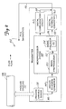
- FIG. 2 a block diagram shows one embodiment of a transmitter 102 configured as a diagnostic device in accordance with the invention.
- diagnostic devices include control system 104, magnetic flowmeter 250 (FIG. 7), vortex flowmeter 260 (FIG. 8) and coriolis flowmeter 330 (FIG. 9).
- Transmitter 102 senses a process variable of process fluid in pipe 130 with process variable sensor 138.
- Transmitter 102 includes a process coupling 132 which couples a process variable sensor 138 to process fluid in pipe 130.
- coupling 132 can comprise impulse lines 136 and flange 140 for transmitter 102, flow tube 252 for magnetic flowmeter 250, flow tube 264 and shedding bar 262 for vortex flowmeter 260, or flow tube 332 and measurement tubes 336 for coriolis flowmeter 330.
- process variable sensors 138 include a pressure sensor, electrodes 258 (FIG. 7), sensor 266 (FIG. 8), and coils 342 (FIG. 9).
- Analog to digital converter 144 receives sensor input 146 from process variable sensor 138 which is related to a process variable of the process fluid. Analog to digital converter 144 provides a digitized sensor signal to microprocessor system 148.
- Microprocessor system 148 includes signal preprocessor 150 which is coupled to sensor input 146 through analog to digital converter 144 and isolates signal components in the sensor signal such as frequencies, amplitudes or signal characteristics which are related to operation of the process.
- Signal preprocessor 150 provides an isolated signal output 152 to signal evaluator 154.
- Signal preprocessor isolates a portion of the process variable signal by filtering, performing a wavelet transform, performing a Fourier transform, use of a neural network, statistical analysis, or other signal evaluation techniques.
- the isolated signal output is related to vibration noise signals 132 in the process fluid sensed by sensor 138.
- Signal evaluator 154 includes memory 155 and provides a condition output 156 which is related to a condition of the process.
- Signal evaluator 154 evaluates the isolated signal output 152 based upon a rule, fuzzy logic, a neural network, an expert system, a wavelet analysis or other signal evaluation technique.
- Process conditions include condition, diagnostic, health, or time to failure information related to valves, pumps, pump seals, discharge systems, actuators, solenoids, compressors, turbines, agitators, dampers, piping, fixtures, tanks, or other components of a process control system.
- Signal preprocessor 150 and signal evaluator 154 isolate and evaluate sensor signal components as shown in flow chart 200 of FIG. 6.
- Microprocessor system 148 further calculates a process variable based upon the sensor signal input 146 in accordance with known techniques.
- a digital to analog converter 158 coupled to microprocessor system 148 generates an analog transmitter output 160 for coupling to communication bus 106.
- a digital communication circuit 162 generates a transmitter output 164.
- the analog output 160 and the diagnostic data 164 can be coupled to indicators or controllers as desired.
- Signal preprocessor 150 is configured to isolate signal components which are related to vibration noise signals 132 in the process fluid.
- the signal components are isolated through signal processing techniques in which only desired frequencies or other signal characteristics such as amplitude are identified and an indication of their identification is provided on an isolated signal output 152.
- signal preprocessor can comprise a filter, for example a band pass filter, to generate the isolated signal output 152.
- advanced signal processing techniques are utilized such as a Fast Fourier transform (FFT) to obtain the spectrum of the sensor signal.
- FFT Fast Fourier transform
- signal preprocessor 150 comprises a wavelet processor which performs a wavelet analysis on the sensor signal as shown in FIGS. 3, 4 and 5 using a discrete wavelet transform. Wavelet analysis is well suited for analyzing signals which have transients or other non-stationary characteristics in the time domain. In contrast to Fourier transforms, wavelet analysis retains information in the time domain, i.e., when the event occurred.
- Wavelet analysis is a technique for transforming a time domain signal into the frequency domain which, like a Fourier transformation, allows the frequency components to be identified.
- the output includes information related to time. This may be expressed in the form of a three dimensional graph with time shown on one axis, frequency on a second axis and signal amplitude on a third axis.
- a discussion of wavelet analysis is given in On-Line Tool Condition Monitoring System With Wavelet Fuzzy Neural Network, by L. Xiaoli et al., 8 JOURNAL OF INTELLIGENT MANUFACTURING pgs. 271-276 (1997).
- a portion of the sensor signal is windowed and convolved with a wavelet function.
- This convolution is performed by superimposing the wavelet function at the beginning of a sample, multiplying the wavelet function with the signal and then integrating the result over the sample period.
- the result of the integration is scaled and provides the first value for continuous wavelet transform at time equals zero. This point may be then mapped onto a three dimensional plane.
- the wavelet function is then shifted right (forward in time) and the multiplication and integration steps are repeated to obtain another set of data points which are mapped onto the 3-D space. This process is repeated and the wavelet is moved (convolved) through the entire signal.
- the wavelet function is then scaled, which changes the frequency resolution of the transformation, and the above steps are repeated.
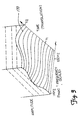
- FIG. 3 Data from a wavelet transformation of a sensor signal from process variable sensor 138 is shown in FIG. 3.
- the data are graphed in three dimensions and form a surface 170.
- the sensor signal includes a small signal peak at about 1 kHz at time t 1 and another peak at about 100 Hz at time t 2 due to vibration noise signal 132.
- signal evaluator 154 Through subsequent processing by signal evaluator 154, surface 170 or portions of surface 170 are evaluated to provide condition output 156.
- signal preprocessor 150 performs a discrete wavelet transform (DWT) which is well suited for implementation in microprocessor system 148.
- DWT discrete wavelet transform
- One efficient discrete wavelet transform uses the Mallat algorithm which is a two channel sub-band coder.
- the Mallet algorithm provides a series of separated or decomposed signals which are representative of individual frequency components of the original signal.
- FIG. 4 shows an example of such a system in which an original sensor signal S is decomposed using a sub-band coder of a Mallet algorithm.
- the signal S has a frequency range from 0 to a maximum of f MAX .
- the signal is passed simultaneously through a first high pass filter having a frequency range from 1/2 f MAX to f MAX , and a low pass filter having a frequency range from 0 to 1/2 f MAX .
- This process is called decomposition.
- the output from the high pass filter provides "level 1" discrete wavelet transform coefficients.
- the level 1 coefficients represent the amplitude as a function of time of that portion of the input signal which is between 1/2 f max and f MAX .
- the output from the 0 - 1/2 f max low pass filter is passed through subsequent high pass (1/4 f max - 1/2 f max ) and low pass (0 - 1/4 f max ) filters, as desired, to provide additional levels (beyond "level 1") of discrete wavelet transform coefficients.
- each low pass filter can be subjected to further decompositions offering additional levels of discrete wavelet transformation coefficients as desired. This process continues until the desired resolution is achieved or the number of remaining data samples after a decomposition yields no additional information.
- the resolution of the wavelet transform is chosen to be approximately the same as the sensor or the same as the minimum signal resolution required to monitor the vibration noise signal 132.
- Each level of DWT coefficients is representative of signal amplitude as a function of time for a given frequency range. Coefficients for each frequency range are concatenated to form a graph such as that shown in FIG. 3.
- padding is added to the signal by adding data to the sensor signal near the borders of windows used in the wavelet analysis. This padding reduces distortions in the frequency domain output.
- This technique can be used with a continuous wavelet transform or a discrete wavelet transform.
- “Padding” is defined as appending extra data on either side of the current active data window, for example, extra data points are added which extend 25% of the current window beyond either window edge.
- the padding is generated by repeating a portion of the data in the current window so that the added data "pads" the existing signal on either side. The entire data set is then fit to a quadratic equation which is used to extrapolate the signal 25% beyond the active data window.
- FIG. 5 is an example showing a signal S generated by sensor 138 and the resultant approximation signals yielded in seven decomposition levels labelled level 1 through level 7.
- signal level 7 is representative of the lowest frequency DWT coefficient which can be generated. Any further decomposition yields noise. All levels, or only those levels which relate vibration noise signal 132, are provided as isolated signal 152 to signal evaluator 154. For example, depending on the particular system configuration and sensor type, levels 2, 3 and 5 can comprise the isolated signal 152 provided to signal evaluator 154.
- Signal evaluator 154 evaluates the isolated signal 152 received from signal preprocessor 150 and in one embodiment, monitors an amplitude of a certain frequency or range of frequencies identified in isolated signal 152 and provides the condition output 156 if a threshold is exceeded. For example, if the isolated signal 152 comprises those components of sensor signal between 45 and 55 Hz, sensor evaluator 154 can provide condition output 156 if a threshold is exceeded indicative of a condition in the process such as a bearing failure in pump control device 108 or cavitation in valve control device 110. Signal evaluator can also comprise more advanced decision making algorithms such as fuzzy logic, neural networks, expert systems, rule based systems, etc. Commonly assigned U.S. Patent Application No. 08/623,569 describes various decision making systems which can be implemented in signal evaluator 154 and is incorporated herein by reference.
- FIG. 6A a flow chart 180 of a method of diagnosis performed in a diagnostic device capable of receiving a process variable is shown.
- the algorithm starts at 182 and a process variable sensor signal is obtained.
- the process noise signal which is present in the process variable signal is isolated at 184.
- the isolated process noise signal is evaluated at 186 and an output indicative of the process condition is provided at 188 in response to the evaluated isolated process noise signal.
- FIG. 6B is a more detailed flow chart 200 of the method of diagnosis.
- the algorithm starts at 202 and a process variable sensor signal is obtained. Components, X 1 , X 2 , X 3 , X 4 ... X N are isolated at 204. (For simplicity, flow chart 200 shows only 4 components X 1 - X 4 ).
- control is passed to block 202 and the process variable sensor signal is again obtained.
- the isolated component X 1 , X 2 , X 3 , X 4 , respectively, are output. Each output is indicative of the presence of a particular signal component in the process variable sensor signal.
- the isolated components are evaluated at 214, 216, 218 and 220. In the signal evaluation illustrated in FIG. 6, a rule is used in which the isolated signal component is compared to a limit (limit 1 , limit 2 , limit 3 , limit 4 , respectively). If none of the limits have been exceeded by the respective isolated signal, the algorithm returns to 202 to obtain an updated process variable signal.
- condition 1 can comprise signal components of the process variable sensor signal between 45 and 55 Hz. If these components have a signal strength which is greater than a limit specified by limit 2 , condition 2 is output which can indicate that a pump, for example, in the process is failing. Similarly, other components in the sensor signal indicate the condition of other aspects of the process control system. If a single component is indicative of a condition of more than one aspect of the process, the output indicates that there are two possible conditions in the process.
- condition output is not necessarily tied to a specific failure and can simply indicate that a particular signal component has exceeded a threshold or has some other characteristic.
- steps 202-212 are performed by signal preprocessor 150 of FIG. 2 and steps 214-226 are performed by signal evaluator 154.
- steps of isolating and evaluating can be combined and performed simultaneously or by the same components in a diagnostic device.
- wavelet transformation data is calculated and stored in memory 155 of signal evaluator 154 shown in FIG. 2 during normal operation of the process. This data represents a base "plane" of normal operation. The data can be collected at various times during the day, during a process cycle and during the year. When placed into normal use, signal evaluator 154 retrieves the stored wavelet transformation from memory 155 and compares the base plane data with information gathered through wavelet analysis during operation.
- a neural network can operate in microprocessor system 148 to monitor operation of the process and select the optimum model stored in memory 155. Coefficients related to operation of the model can be generated using a neural network or can be received over communication bus 106 during installation of transmitter 102 as provided for in various communication protocols.
- models include a first order model including dead time which is typically good for non-oscillatory systems, or second order models plus dead time which typically suffice for oscillatory processes.
- Another modeling technique is to use an adaptive neural network-fuzzy logic model.
- Such a hybrid system includes a neural network and fuzzy logic.
- the fuzzy logic adapts the model to variability of the process while the neural network models allow flexibility of the modeling to thereby adjust to changing processes. This provides a relatively robust model.
- the use of adaptive membership functions in the fuzzy logic model further allows the determination whether the particular model should be updated.
- the diagnostic device can operate with any appropriate type of signal evaluator such as one that includes life expectancy or diagnostic circuitry. Examples of such techniques are shown in the co-pending application Serial No. 08/744,980, filed November 7, 1996, entitled “DIAGNOSTICS FOR RESISTANCE BASED TRANSMITTER.”
- the process variable sensor 138 can be any type of process variable sensor which is capable of sensing vibrations in the process fluid.
- the process variable sensor should have a bandwidth and a frequency response or resolution sufficient to detect the desired vibration noise signals. Typically, this is between about 0 and about 200 Hz in a differential pressure based flow transmitter.
- One type of process variable sensor is a pressure sensor.
- a process variable pressure sensor having sufficient bandwidth is illustrated in U.S. Patent No. 5,637,802, issued June 10, 1997.
- Other components in the devices such as analog to digital converters must also have sufficient bandwidth, amplifiers and other elements in the input channel.
- FIG. 7 illustrates a magnetic flowmeter 250 having a process variable sensor provided by electrodes 258.
- Flowmeter 250 includes flow tube 252 coupled to electronics housing 254.
- coils 256 In a magnetic flowmeter, coils 256 generate a magnetic field in flow tube 252. The flow of process fluid through the resultant magnetic field develops an electric potential between electrodes 258 which provide a process variable sensor signal. Vibration signals 132 in the fluid change the flow rate and can be sensed by electrodes 258. Typical frequency response of magnetic flowmeters are 0-75 Hz or higher.
- FIG. 8 illustrates a vortex flowmeter 260 having a process variable sensor provided by sensor 266.
- Vortex flowmeter 260 includes a shedding bar 262 mounted in flow tube 264 and coupled to fourth sensor 266.
- a flow of process fluid through flow tube 264 causes shedding bar 262 to move about pivot axis 268. This movement causes a force 270 to be transferred to sensor 266 which provides a process variable sensor signal.
- the frequency of this force is related to the flow through flow tube 264.
- Noise vibration signals 132 are also transferred to sensor 266 for use with the signal preprocessor 150 and signal evaluator 154 shown in FIG. 2.
- Vortex flowmeters typically have a frequency response of between about 0 and 10 KHz or higher.
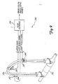
- FIG. 9 illustrates a coriolis flowmeter 330 process variable sensor provided by coils 342 and which includes a flow tube 332 and meter electronics 334.
- Measurement tubes 336 are coupled to flow tube 332.
- a drive coil 340 vibrates tubes 336 in response to a drive signal and sense elements which include sense coils 342 and sense magnets 344 provide left and right velocity signals related to the resultant vibration of tubes 336.
- Flow through the tubes 336 cause tubes 336 to pivot in a manner which is sensed by coils 342.
- the outputs from coils 342 are related to flow through tubes 336 and provide a process variable sensor signal.
- Vibration noise signals 132 can also be sensed by coils 342 and provided to signal preprocessor 140 shown in FIG. 2.
- Coriolis meters typically have a very wide frequency response which can sense vibrations at very high frequencies.
- process variable sensors include an ultrasonic or radio frequency receiver in a level gauge or an ultrasonic receiver in a ultrasonic level sensor.
- transmitter 102 can comprise an ultrasonic flowmeter or level gauge and sensor 138 is an ultrasonic sensor.
- control devices such as valve controllers can include process variable sensors.
- a microprocessor When implemented in software, a microprocessor performs the functions and the signals comprise digital values on which the software operates.
- a general purpose processor programmed with instructions that cause the processor to perform the desired process elements, application specific hardware components that contain circuit wired to perform the desired elements and any combination of programming a general purpose processor and hardware components can be used. Deterministic or fuzzy logic techniques can be used as needed to make decisions in the circuitry or software. Because of the nature of complex digital circuitry, circuit elements may not be partitioned into separate blocks as shown, but components used for various functional blocks can be intermingled and shared. Likewise with software, some instructions can be shared as part of several functions and be intermingled with unrelated instructions within the scope of the invention.
- a diagnostic device can be any device (or a combination of devices such as devices which share information to arrive at a conclusion) which receives a process variable signal including a process monitoring system, a personal computer, a control system, a portable communicator, a controller or a transmitter.
- U.S. Patent No. 5,754,596 describes a technique for transmitting stored data which has been stored in a field device such that the stored data can have a higher bandwidth than would be possible if data were transmitted at the update rate of the communication protocol. Any type of process variable sensor which is sensitive to a process noise signal can be used with the diagnostic device of the invention.
Landscapes
- Physics & Mathematics (AREA)
- General Physics & Mathematics (AREA)
- Engineering & Computer Science (AREA)
- Automation & Control Theory (AREA)
- Artificial Intelligence (AREA)
- Evolutionary Computation (AREA)
- Mathematical Physics (AREA)
- Measuring Volume Flow (AREA)
- Testing And Monitoring For Control Systems (AREA)
- Testing Or Calibration Of Command Recording Devices (AREA)
Claims (28)
- Fehlerdiagnosevorrichtung zur Verwendung in einem Prozesssteuerungssystem zur Steuerung oder Überwachung eines Prozessfluids, wobei die Vorrichtung betriebsbereit ist, um Folgendes zu empfangen:eine Sensor-Signaleingabe (146), wobei das Sensorsignal mit einer Prozessvariablen eines Prozessfluids eines Prozesses in Zusammenhang steht, und die Prozessvariable mit Hilfe eines Prozessvariablensensors (138) gemessen wird,wobei die Fehlerdiagnosevorrichtung Folgendes aufweist:eine Signal-Vorverarbeitungsvorrichtung (150), die betriebsbereit ist, um die Sensor-Signaleingabe (146) zu empfangen und eine isolierte Signalausgabe (152) zu erzeugen, wobei das Sensorsignal Signalkomponenten aufweist, die mit dem Prozessbetrieb in Zusammenhang stehen; undeine Signal-Bewertungseinrichtung (154), die für den Empfang der isolierten Signalausgabe (152) und für die Erzeugung eines Zustands-Ausgangssignals (156), das mit einem Zustand des Prozesses in Zusammenhang steht, betriebsbereit ist, wobei der Zustand des Prozesses nicht direkt mit der Prozessvariablen in Zusammenhang steht;dadurch gekennzeichnet, dass die Signal-Vorverarbeitungseinrichtung (150) betriebsbereit ist, um einen Frequenzbereich zu isolieren, der mit Schwingungs-Rauschsignalen in Zusammenhang steht, wodurch die isolierte Signalausgabe (152) erzeugt wird; und
dass die Signal-Bewertungseinrichtung (154) betriebsbereit ist, um eine Amplitude der isolierten Signalausgabe (152) mit einem Schwellenpegel zu vergleichen, wodurch das Zustands-Ausgangssignal (156) erzeugt wird. - Fehlerdiagnosevorrichtung nach Anspruch 1, dadurch gekennzeichnet, dass das Sensorsignal einen Frequenzgang von mindestens 50 Hz aufweist.
- Fehlerdiagnosevorrichtung nach Anspruch 1 oder Anspruch 2, dadurch gekennzeichnet, dass der Prozessvariablensensor (138) einen Durcksensor, einen Sensor in einem Coriolis-Durchflussmesser und/oder in einem Ultraschall-Durchflussmesser aufweist.
- Fehlerdiagnosevorrichtung nach einem der Ansprüche 1 bis 3, dadurch gekennzeichnet, dass das Sensorsignal eine Frequenz aufweist, die zwischen 0 Hz und 200 Hz liegt.
- Fehlerdiagnosevorrichtung nach einem der Ansprüche 1 bis 4, dadurch gekennzeichnet, dass die Signal-Vorverarbeitungseinrichtung (150) ein Filter aufweist.
- Fehlerdiagnosevorrichtung nach einem der Ansprüche 1 bis 4, dadurch gekennzeichnet, dass die Signal-Vorverarbeitungseinrichtung (150) eine Wavelet-Vorverarbeitungseinrichtung aufweist, die betriebsbereit ist, um das Sensorsignal zu empfangen und eine Wavelet-Transformation auszuführen.
- Fehlerdiagnosevorrichtung nach Anspruch 6, dadurch gekennzeichnet, dass die Wavelet-Vorverarbeitungsvorrichtung betriebsbereit ist, um eine diskrete Wavelet-Transformation auszuführen.
- Fehlerdiagnosevorrichtung nach Anspruch 7, dadurch gekennzeichnet, dass die Wavelet-Vorverarbeitungseinrichtung betriebsbereit ist, um die diskrete Wavelet-Transformation unter Verwendung des Mallat-Algorithmus auszuführen.
- Fehlerdiagnosevorrichtung nach einem der Ansprüche 1 bis 8, dadurch gekennzeichnet, dass der Zustand mit dem Betrieb einer Prozesssteuerungsvorrichtung in Zusammenhang steht.
- Fehlerdiagnosevorrichtung nach einem der Ansprüche 1 bis 9, dadurch gekennzeichnet, dass die Fehlerdiagnosevorrichtung in einem Prozessmonitor oder in einem Steuersystem implementiert ist.
- Fehlerdiagnosevorrichtung nach einem der Ansprüche 1 bis 10, dadurch gekennzeichnet, dass die Fehlerdiagnosevorrichtung an einen Kommunikationsbus koppelt.
- Fehlerdiagnosevorrichtung nach Anspruch 11, dadurch gekennzeichnet, dass der Kommunikationsbus eine Zweidrahtschleife aufweist.
- Fehlerdiagnosevorrichtung nach Anspruch 11, dadurch gekennzeichnet, dass die Fehlerdiagnosevorrichtung vollständig mit Energie betrieben wird, die von der Zweidrahtschleife erhalten wird.
- Fehlerdiagnosevorrichtung nach einem der Ansprüche 1 bis 13, dadurch gekennzeichnet, dass der Zustand des Prozesses mit einem Zustand einer Prozessvorrichtung, die aus der Gruppe von Vorrichtungen bestehend aus Ventilen, Pumpen, Pumpendichtungen, Entladesystemen, Stellgliedern, Elektromagneten oder Solenoiden, Verdichtern, Turbinen, Rührwerken, Dämpfern, Rohrleitungen, Montagevorrichtugen und Tanken ausgewählt wird, in Zusammenhang steht.
- Fehlerdiagnoseverfahren, welches in einer Prozesssteuerungsumgebung ausgeführt wird und folgende Schritte aufweist:Erhalt eines Prozessvariablen-Sensorsignals (146);Isolierung eines Prozess-Rauschsignals (152) in dem Prozessvariablen-Sensorsignal (146) durch Isolieren eines mit den Schwingungs-Rauschsignalen in Zusammenhang stehenden Frequenzbereichs ; und wobei das Verfahren gekennzeichnet ist durch
die Bewertung des isolierten Signals (152) durch Vergleichen einer Amplitude des isolierten Prozess-Rauschsignals (152) mit einem Schwellenpegel und Bereitstellen eines mit dem Prozess in Zusammenhang stehenden Zustands-Ausgangssignals (156), wobei der Zustand nicht direkt mit der Prozessvariablen in Zusammenhang steht. - Verfahren nach Anspruch 15, dadurch gekennzeichnet, dass die Isolierung das Filtern des Prozessvariablen-Sensorsignals (146) aufweist.
- Verfahren nach Anspruch 15, dadurch gekennzeichnet, dass die Isolierung das Ausführen einer Wavelet-Transformation an dem Prozessvariablen-Sensorsignal aufweist.
- Verfahren nach Anspruch 17, dadurch gekennzeichnet, dass die Ausführung eines Wavelet-Transformatiorisvorgangs die Ausführung einer diskreten Wavelet-Transformation einschließt.
- Verfahren nach Anspruch 18, dadurch gekennzeichnet, dass die Durchführung einer diskreten Wavelet-Transformation die Verwendung eines Mallat-Algorithmus aufweist.
- Verfahren nach einem der Ansprüche 17 bis 19, wobei das Verfahren weiter die Schritte des Abrufens von während dem Normalbetrieb in einem Speicher (155) einer Signal-Bewertungseinrichtung (154) gespeicherten Wavelet-Transformationsdaten, wobei die Signal-Bewertungseinrichtung das isolierte Signal (152) bewertet, und des Vergleichens der vorliegenden Wavelet-Transformationsdaten mit den abgerufenen Wavelet-Transformationsdaten aufweist.
- Verfahren nach Anspruch 20, welches weiter die Subtraktion der abgerufenen Wavelet-Transformationsdaten von den gegenwärtigen Wavelet-Transformationsdaten aufweist.
- Verfahren nach einem der Ansprüche 15 bis 21, dadurch gekennzeichnet, dass der Bewertungsschritt die Anlegung des isolierten Signals (152) an ein Neuronennetz und/oder die Anwendung einer Formel bei dem isolierten Signal (152) aufweist.
- Verfahren nach einem der Ansprüche 15 bis 22, dadurch gekennzeichnet, dass das Prozessvariablen-Sensorsignal ein Drucksensorsignal, ein Sensorausgangssignal aus einem Coriolis-Durchflussmesser, ein Sensorausgangssignal aus einem Wirbeldurchflussmesser, Elektroden-Ausgangssignale aus einem magnetischen Durchflussmesser und/oder ein Ausgangssignal aus einem Sensor in einem Coriolis-Durchflussmesser aufweist.
- Verfahren nach einem der Ansprüche 15 bis 23, dadurch gekennzeichnet, dass das Prozessvariablen-Sensorsignal eine Bandbreite von mindestens ungefähr 50 Hz aufweist.
- Verfahren nach einem der Ansprüche 15 bis 24, dadurch gekennzeichnet, dass das Zustands-Ausgangssignal mit einem Zustand einer Prozesssteuerungsvorrichtung in Zusammenhang steht.
- Verfahren nach einem der Ansprüche 15 bis 25, welches das vollständige Betreiben der Fehlerdiagnosevorrichtung mit Energie von einer Zweidrahtschleife einschließt.
- Prozesssender, welcher ein Fehlerdiagnoseverfahren nach Anspruch 15 durchführt, wobei der Sender Folgendes aufweist:einen Prozessvariablensensor (138), welcher ein für einen Parameter des Prozesses kennzeichnendes Eingangssignal empfängt und ein Ausgangssignal (146) bereitstellt, das mit dem Parameter in Zusammenhang steht, wobei das Ausgangssignal (146) das Prozessvariablen-Sensorsignal (146) aufweist;eine Vorrichtung (150) für das Trennen des Prozess-Rauschsignals (152) von dem Ausgangssignal (146); undeine Signal-Bewertungseinrichtung (154), welche das isolierte Prozess-Rauschsignal (152) bewertet, indem sie eine Amplitude des isolierten Prozess-Rauschsignals (152) mit einem Schwellenpegel vergleicht und ein mit dem Prozess in Zusammenhang stehendes Zustands-Ausgangssignal (156) liefert, wobei der Zustand des Prozesses mit der Prozessvariablen nicht direkt in Zusammenhang steht.
- Computerlesbares Medium mit darauf gespeicherten Befehlen, die von einem Mikroprozessorsystem in einer Fehlerdiagnosevorrichtung zur Diagnose eines Zustands eines Prozesses ausführbar sind, wobei die Befehle Folgendes umfassen:Erhalt eines Prozessvariablen-Sensorsignal (146);Isolierung eines Prozess-Rauschsignals (152) in dem Prozessvariablen-Sensorsignal (146) durch Isolieren eines Frequenzbereichs, der mit Schwingungs-Rauschsignalen in Zusammenhang steht; und gekennzeichnet ist durch Bewerten des isolierten Prozess-Rauschsignals (152) durch Vergleichen einer Amplitude des isolierten Prozess-Rauschsignals (152) mit einem Schwellenpegel, wobei der Zustand nicht direkt mit der Prozessvariablen in Zusammenhang steht; undAusgabe der Prozesszustands (156) ansprechend auf die Bewertung.
Applications Claiming Priority (3)
| Application Number | Priority Date | Filing Date | Title |
|---|---|---|---|
| US344631 | 1999-06-25 | ||
| US09/344,631 US6601005B1 (en) | 1996-11-07 | 1999-06-25 | Process device diagnostics using process variable sensor signal |
| PCT/US2000/014798 WO2001001213A1 (en) | 1999-06-25 | 2000-05-30 | Process device diagnostics using process variable sensor signal |
Publications (2)
| Publication Number | Publication Date |
|---|---|
| EP1190282A1 EP1190282A1 (de) | 2002-03-27 |
| EP1190282B1 true EP1190282B1 (de) | 2006-09-13 |
Family
ID=23351312
Family Applications (1)
| Application Number | Title | Priority Date | Filing Date |
|---|---|---|---|
| EP00937914A Expired - Lifetime EP1190282B1 (de) | 1999-06-25 | 2000-05-30 | Fehlerdiagnose einer prozesseinrichtung unter verwendung eines prozessabhängigen sensorsignals |
Country Status (6)
| Country | Link |
|---|---|
| US (1) | US6601005B1 (de) |
| EP (1) | EP1190282B1 (de) |
| JP (1) | JP2003503784A (de) |
| AU (1) | AU5302700A (de) |
| DE (1) | DE60030715T2 (de) |
| WO (1) | WO2001001213A1 (de) |
Families Citing this family (146)
| Publication number | Priority date | Publication date | Assignee | Title |
|---|---|---|---|---|
| US7949495B2 (en) | 1996-03-28 | 2011-05-24 | Rosemount, Inc. | Process variable transmitter with diagnostics |
| US7630861B2 (en) | 1996-03-28 | 2009-12-08 | Rosemount Inc. | Dedicated process diagnostic device |
| US8290721B2 (en) | 1996-03-28 | 2012-10-16 | Rosemount Inc. | Flow measurement diagnostics |
| US7623932B2 (en) | 1996-03-28 | 2009-11-24 | Fisher-Rosemount Systems, Inc. | Rule set for root cause diagnostics |
| US7085610B2 (en) | 1996-03-28 | 2006-08-01 | Fisher-Rosemount Systems, Inc. | Root cause diagnostics |
| US7254518B2 (en) * | 1996-03-28 | 2007-08-07 | Rosemount Inc. | Pressure transmitter with diagnostics |
| US7010459B2 (en) * | 1999-06-25 | 2006-03-07 | Rosemount Inc. | Process device diagnostics using process variable sensor signal |
| US7457785B1 (en) | 2000-08-25 | 2008-11-25 | Battelle Memorial Institute | Method and apparatus to predict the remaining service life of an operating system |
| US20040063710A1 (en) * | 2000-11-22 | 2004-04-01 | Tomiya Mano | Ophthalmological preparations |
| US7426452B2 (en) * | 2001-12-06 | 2008-09-16 | Fisher-Rosemount Systems. Inc. | Dual protocol handheld field maintenance tool with radio-frequency communication |
| RU2299458C2 (ru) * | 2001-12-06 | 2007-05-20 | Фишер-Роузмаунт Системз, Инк. | Искробезопасный инструмент для технического обслуживания в полевых условиях |
| US20030229472A1 (en) * | 2001-12-06 | 2003-12-11 | Kantzes Christopher P. | Field maintenance tool with improved device description communication and storage |
| US20030204373A1 (en) * | 2001-12-06 | 2003-10-30 | Fisher-Rosemount Systems, Inc. | Wireless communication method between handheld field maintenance tools |
| US6853951B2 (en) | 2001-12-07 | 2005-02-08 | Battelle Memorial Institute | Methods and systems for analyzing the degradation and failure of mechanical systems |
| US7359803B2 (en) * | 2002-01-23 | 2008-04-15 | Cidra Corporation | Apparatus and method for measuring parameters of a mixture having solid particles suspended in a fluid flowing in a pipe |
| US7032432B2 (en) * | 2002-01-23 | 2006-04-25 | Cidra Corporation | Apparatus and method for measuring parameters of a mixture having liquid droplets suspended in a vapor flowing in a pipe |
| US7275421B2 (en) * | 2002-01-23 | 2007-10-02 | Cidra Corporation | Apparatus and method for measuring parameters of a mixture having solid particles suspended in a fluid flowing in a pipe |
| US7039744B2 (en) * | 2002-03-12 | 2006-05-02 | Fisher-Rosemount Systems, Inc. | Movable lead access member for handheld field maintenance tool |
| US7027952B2 (en) * | 2002-03-12 | 2006-04-11 | Fisher-Rosemount Systems, Inc. | Data transmission method for a multi-protocol handheld field maintenance tool |
| US6839644B1 (en) * | 2002-04-01 | 2005-01-04 | The Texas A&M University System | Plumbing supply monitoring, modeling and sizing system and method |
| US7319921B2 (en) * | 2002-05-22 | 2008-01-15 | Underwood Fred R | Water treatment control system |
| US7073392B2 (en) * | 2002-07-19 | 2006-07-11 | Celerity, Inc. | Methods and apparatus for pressure compensation in a mass flow controller |
| JP2005537464A (ja) * | 2002-07-19 | 2005-12-08 | マイクロリス コーポレイション | 流体フロー測定および比例流体フロー制御デバイス |
| NO320915B1 (no) * | 2002-07-30 | 2006-02-13 | Dynatrend As | Fremgangsmate og anordning for a bestemme et turbinblads driftstilstand og a anvende den innsamlede tilstandsinformasjon i en levetidsberegning |
| US7773715B2 (en) | 2002-09-06 | 2010-08-10 | Rosemount Inc. | Two wire transmitter with isolated can output |
| US7757562B2 (en) * | 2002-10-28 | 2010-07-20 | Mbh Data Source | Technique and apparatus for detecting and monitoring internal defect conditions of mud pumps |
| US10261506B2 (en) * | 2002-12-05 | 2019-04-16 | Fisher-Rosemount Systems, Inc. | Method of adding software to a field maintenance tool |
| DE10258921A1 (de) * | 2002-12-17 | 2004-07-01 | Abb Research Ltd. | Verfahren und Einrichtung zum Regeln einer Regelgröße |
| CA2513248C (en) * | 2003-01-13 | 2013-01-08 | Cidra Corporation | Apparatus and method using an array of ultrasonic sensors for determining the velocity of a fluid within a pipe |
| US7096719B2 (en) * | 2003-01-13 | 2006-08-29 | Cidra Corporation | Apparatus for measuring parameters of a flowing multiphase mixture |
| TWI386578B (zh) | 2003-01-17 | 2013-02-21 | Applied Materials Inc | 避免一質量流量控制器涉及一質量流量控制器陣列中之干擾的方法 |
| DE112004000385T5 (de) * | 2003-03-06 | 2006-02-16 | Fisher-Rosemount Systems Inc. | Wärmefluss-regulierende Abdeckung für eine elektrische Speicherzelle |
| US7512521B2 (en) * | 2003-04-30 | 2009-03-31 | Fisher-Rosemount Systems, Inc. | Intrinsically safe field maintenance tool with power islands |
| US7054695B2 (en) | 2003-05-15 | 2006-05-30 | Fisher-Rosemount Systems, Inc. | Field maintenance tool with enhanced scripts |
| US6925419B2 (en) * | 2003-05-16 | 2005-08-02 | Fisher-Rosemount Systems, Inc. | Intrinsically safe field maintenance tool with removable battery pack |
| US8874402B2 (en) * | 2003-05-16 | 2014-10-28 | Fisher-Rosemount Systems, Inc. | Physical memory handling for handheld field maintenance tools |
| US7036386B2 (en) * | 2003-05-16 | 2006-05-02 | Fisher-Rosemount Systems, Inc. | Multipurpose utility mounting assembly for handheld field maintenance tool |
| US7526802B2 (en) * | 2003-05-16 | 2009-04-28 | Fisher-Rosemount Systems, Inc. | Memory authentication for intrinsically safe field maintenance tools |
| US7199784B2 (en) * | 2003-05-16 | 2007-04-03 | Fisher Rosemount Systems, Inc. | One-handed operation of a handheld field maintenance tool |
| US7231319B2 (en) * | 2003-06-18 | 2007-06-12 | Eaton Corporation | System and method for proactive motor wellness diagnosis based on potential cavitation faults |
| US6983850B2 (en) * | 2003-06-25 | 2006-01-10 | Krebs Engineers Corporation | Hydrocyclone roping detector and method |
| RU2324171C2 (ru) * | 2003-07-18 | 2008-05-10 | Роузмаунт Инк. | Диагностика процесса |
| US7018800B2 (en) | 2003-08-07 | 2006-03-28 | Rosemount Inc. | Process device with quiescent current diagnostics |
| KR101380291B1 (ko) * | 2003-09-05 | 2014-04-01 | 마이크로 모우션, 인코포레이티드 | 유량계 필터 시스템 및 방법 |
| RU2319113C2 (ru) * | 2003-09-05 | 2008-03-10 | Майкро Моушн, Инк. | Система фильтра расходомера и способ удаления шума из сигнала расходомера (варианты) |
| US7627441B2 (en) | 2003-09-30 | 2009-12-01 | Rosemount Inc. | Process device with vibration based diagnostics |
| US7237440B2 (en) * | 2003-10-10 | 2007-07-03 | Cidra Corporation | Flow measurement apparatus having strain-based sensors and ultrasonic sensors |
| DE10356383B4 (de) * | 2003-12-03 | 2007-06-21 | Abb Patent Gmbh | Coriolis-Massedurchflussmesser |
| DE10361464A1 (de) * | 2003-12-23 | 2005-07-28 | Endress + Hauser Flowtec Ag, Reinach | Vorrichtung zur Bestimmung und/oder Überwachung des Volumen- und/oder Massendurchflusses eines Messmediums |
| US7523667B2 (en) * | 2003-12-23 | 2009-04-28 | Rosemount Inc. | Diagnostics of impulse piping in an industrial process |
| WO2005078237A1 (en) * | 2004-02-05 | 2005-08-25 | Rosemount Inc. | Annulus plugging detection using a pressure transmitter in gas-lift oil production |
| US7330797B2 (en) * | 2004-03-10 | 2008-02-12 | Cidra Corporation | Apparatus and method for measuring settlement of solids in a multiphase flow |
| US7093492B2 (en) * | 2004-03-19 | 2006-08-22 | Mechworks Systems Inc. | Configurable vibration sensor |
| US6920799B1 (en) | 2004-04-15 | 2005-07-26 | Rosemount Inc. | Magnetic flow meter with reference electrode |
| US7046180B2 (en) | 2004-04-21 | 2006-05-16 | Rosemount Inc. | Analog-to-digital converter with range error detection |
| US7426852B1 (en) | 2004-04-26 | 2008-09-23 | Expro Meters, Inc. | Submersible meter for measuring a parameter of gas hold-up of a fluid |
| US7088285B2 (en) * | 2004-05-25 | 2006-08-08 | Rosemount Inc. | Test apparatus for a waveguide sensing level in a container |
| US7536274B2 (en) * | 2004-05-28 | 2009-05-19 | Fisher-Rosemount Systems, Inc. | System and method for detecting an abnormal situation associated with a heater |
| US7464721B2 (en) * | 2004-06-14 | 2008-12-16 | Rosemount Inc. | Process equipment validation |
| US7216019B2 (en) * | 2004-07-08 | 2007-05-08 | Celerity, Inc. | Method and system for a mass flow controller with reduced pressure sensitivity |
| US7866211B2 (en) * | 2004-07-16 | 2011-01-11 | Rosemount Inc. | Fouling and corrosion detector for process control industries |
| EP1787179A2 (de) * | 2004-08-31 | 2007-05-23 | Watlow Electric Manufacturing Company | Betriebssystemverbreitetes diagnosesystem |
| US7991582B2 (en) * | 2004-09-30 | 2011-08-02 | Rosemount Inc. | Process device with diagnostic annunciation |
| CN100573381C (zh) * | 2005-02-15 | 2009-12-23 | Abb研究有限公司 | 用于过程控制系统的诊断设备 |
| US7702478B2 (en) * | 2005-02-28 | 2010-04-20 | Rosemount Inc. | Process connection for process diagnostics |
| ATE511128T1 (de) * | 2005-04-04 | 2011-06-15 | Fisher Rosemount Systems Inc | Statistische verarbeitungsverfahren für die detektion anomaler situationen |
| CA2912218C (en) * | 2005-05-16 | 2018-02-27 | Expro Meters, Inc. | Method and apparatus for detecting and characterizing particles in a multiphase fluid |
| MX2007014705A (es) | 2005-05-27 | 2008-02-15 | Cidra Corp | Un aparato y metodo para medir un parametro de un flujo de fases multiples. |
| US7526966B2 (en) | 2005-05-27 | 2009-05-05 | Expro Meters, Inc. | Apparatus and method for measuring a parameter of a multiphase flow |
| US8112565B2 (en) | 2005-06-08 | 2012-02-07 | Fisher-Rosemount Systems, Inc. | Multi-protocol field device interface with automatic bus detection |
| US8641813B2 (en) | 2005-07-07 | 2014-02-04 | Expro Meters, Inc. | System and method for optimizing a gas/liquid separation process |
| US7664610B2 (en) * | 2005-09-28 | 2010-02-16 | Rosemount Inc. | Steam trap monitoring |
| US20070068225A1 (en) | 2005-09-29 | 2007-03-29 | Brown Gregory C | Leak detector for process valve |
| US8036760B2 (en) * | 2005-10-04 | 2011-10-11 | Fisher-Rosemount Systems, Inc. | Method and apparatus for intelligent control and monitoring in a process control system |
| US7444191B2 (en) | 2005-10-04 | 2008-10-28 | Fisher-Rosemount Systems, Inc. | Process model identification in a process control system |
| US7738975B2 (en) | 2005-10-04 | 2010-06-15 | Fisher-Rosemount Systems, Inc. | Analytical server integrated in a process control network |
| US7579947B2 (en) * | 2005-10-19 | 2009-08-25 | Rosemount Inc. | Industrial process sensor with sensor coating detection |
| DE102005060635A1 (de) * | 2005-12-13 | 2007-06-14 | Siemens Ag | Steuerungsverfahren zur Kühlung einer technischen Anlage |
| DE102006014102A1 (de) | 2005-12-30 | 2007-07-12 | Endress + Hauser Gmbh + Co. Kg | Verfahren zur Inbetriebnahme und/oder zum Betrieb eines Kommunikationssystems |
| US8032234B2 (en) * | 2006-05-16 | 2011-10-04 | Rosemount Inc. | Diagnostics in process control and monitoring systems |
| JP2007310665A (ja) * | 2006-05-18 | 2007-11-29 | Toshiba Corp | プロセス監視装置 |
| US7913566B2 (en) | 2006-05-23 | 2011-03-29 | Rosemount Inc. | Industrial process device utilizing magnetic induction |
| US7624650B2 (en) | 2006-07-27 | 2009-12-01 | Expro Meters, Inc. | Apparatus and method for attenuating acoustic waves propagating within a pipe wall |
| US7509220B2 (en) * | 2006-08-16 | 2009-03-24 | Rosemount Inc. | Inclination measurement in process transmitters |
| DE102006041867B4 (de) * | 2006-09-06 | 2008-12-04 | Continental Automotive Gmbh | Verfahren und Vorrichtung zur Überwachung des Rauschens eines Sensors |
| US7953501B2 (en) | 2006-09-25 | 2011-05-31 | Fisher-Rosemount Systems, Inc. | Industrial process control loop monitor |
| US8788070B2 (en) * | 2006-09-26 | 2014-07-22 | Rosemount Inc. | Automatic field device service adviser |
| WO2008042290A2 (en) | 2006-09-29 | 2008-04-10 | Rosemount Inc. | Magnetic flowmeter with verification |
| US7321846B1 (en) | 2006-10-05 | 2008-01-22 | Rosemount Inc. | Two-wire process control loop diagnostics |
| US7624651B2 (en) * | 2006-10-30 | 2009-12-01 | Expro Meters, Inc. | Apparatus and method for attenuating acoustic waves in pipe walls for clamp-on ultrasonic flow meter |
| US7673526B2 (en) * | 2006-11-01 | 2010-03-09 | Expro Meters, Inc. | Apparatus and method of lensing an ultrasonic beam for an ultrasonic flow meter |
| NO345532B1 (no) | 2006-11-09 | 2021-03-29 | Expro Meters Inc | Apparat og fremgangsmåte for måling av en fluidstrømparameter innenfor en intern passasje i et langstrakt legme |
| DE102006058689A1 (de) * | 2006-12-13 | 2008-06-19 | Mannesmann Plastics Machinery Gmbh | Verfahren und Vorrichtung zum Diagnostizieren des Zustandes eines Maschinenbauteils |
| US8983667B2 (en) | 2006-12-20 | 2015-03-17 | Data Flow Systems, Inc. | Fluid flow management through a wastewater level manipulation system and associated methods |
| US8594851B1 (en) | 2006-12-20 | 2013-11-26 | Data Flow Systems, Inc. | Wastewater collection flow management system and techniques |
| US8600568B2 (en) * | 2006-12-20 | 2013-12-03 | Data Flow Systems, Inc. | Fluid flow management system and associated methods |
| US8050875B2 (en) * | 2006-12-26 | 2011-11-01 | Rosemount Inc. | Steam trap monitoring |
| DE102007021099A1 (de) | 2007-05-03 | 2008-11-13 | Endress + Hauser (Deutschland) Ag + Co. Kg | Verfahren zum Inbetriebnehmen und/oder Rekonfigurieren eines programmierbaren Feldmeßgeräts |
| CN102385346B (zh) * | 2007-06-13 | 2015-07-29 | 费希尔-罗斯蒙德系统公司 | 手持现场维护工具的改进功能 |
| CN101802314B (zh) * | 2007-07-20 | 2013-05-29 | 罗斯蒙德公司 | 过程流体脉动的差压诊断 |
| US7770459B2 (en) * | 2007-07-20 | 2010-08-10 | Rosemount Inc. | Differential pressure diagnostic for process fluid pulsations |
| US8898036B2 (en) * | 2007-08-06 | 2014-11-25 | Rosemount Inc. | Process variable transmitter with acceleration sensor |
| US8301676B2 (en) | 2007-08-23 | 2012-10-30 | Fisher-Rosemount Systems, Inc. | Field device with capability of calculating digital filter coefficients |
| US7702401B2 (en) | 2007-09-05 | 2010-04-20 | Fisher-Rosemount Systems, Inc. | System for preserving and displaying process control data associated with an abnormal situation |
| US7590511B2 (en) | 2007-09-25 | 2009-09-15 | Rosemount Inc. | Field device for digital process control loop diagnostics |
| US8055479B2 (en) | 2007-10-10 | 2011-11-08 | Fisher-Rosemount Systems, Inc. | Simplified algorithm for abnormal situation prevention in load following applications including plugged line diagnostics in a dynamic process |
| US7484416B1 (en) * | 2007-10-15 | 2009-02-03 | Rosemount Inc. | Process control transmitter with vibration sensor |
| US7693606B2 (en) * | 2007-12-21 | 2010-04-06 | Rosemount Inc. | Diagnostics for mass flow control |
| US8250924B2 (en) | 2008-04-22 | 2012-08-28 | Rosemount Inc. | Industrial process device utilizing piezoelectric transducer |
| US8165849B2 (en) * | 2008-07-14 | 2012-04-24 | General Electric Company | Medical equipment monitoring method and system |
| JP5125857B2 (ja) * | 2008-07-31 | 2013-01-23 | 横河電機株式会社 | プラント診断装置 |
| DE102008042969A1 (de) * | 2008-10-20 | 2010-04-22 | Endress + Hauser Conducta Gesellschaft für Mess- und Regeltechnik mbH + Co. KG | Verfahren und Vorrichtung zur Detektion von Prozesszuständen in alternierenden Produktionsprozessen |
| US7779702B2 (en) * | 2008-11-03 | 2010-08-24 | Rosemount Inc. | Flow disturbance compensation for magnetic flowmeter |
| US7977924B2 (en) | 2008-11-03 | 2011-07-12 | Rosemount Inc. | Industrial process power scavenging device and method of deriving process device power from an industrial process |
| US8175850B2 (en) * | 2008-11-26 | 2012-05-08 | General Electric Company | Monitoring system with dynamically configurable non-interfering signal processing |
| US8085156B2 (en) * | 2009-04-08 | 2011-12-27 | Rosemount Inc. | RF cavity-based process fluid sensor |
| US10156480B2 (en) * | 2009-09-03 | 2018-12-18 | Rosemount Inc. | Thermowell vibration frequency diagnostic |
| CN101718396B (zh) * | 2009-11-30 | 2012-11-21 | 东北大学 | 基于小波和模式识别的流体输送管道泄漏检测方法及装置 |
| DE102010028697B3 (de) | 2010-05-06 | 2011-11-10 | Rovema Gmbh | Dosiervorrichtung mit Schadensüberwachung |
| DE102011009894A1 (de) | 2011-01-31 | 2012-08-02 | Krohne Messtechnik Gmbh | Vortex-Durchflussmessgerät |
| US9207670B2 (en) | 2011-03-21 | 2015-12-08 | Rosemount Inc. | Degrading sensor detection implemented within a transmitter |
| RU2601186C2 (ru) * | 2012-05-29 | 2016-10-27 | Роузмаунт Инк. | Проверка тока контура управления процессом |
| US9528629B2 (en) * | 2012-06-27 | 2016-12-27 | Fisher Controls International Llc | Methods and apparatus to use vibration data to determine a condition of a process control device |
| US9052240B2 (en) | 2012-06-29 | 2015-06-09 | Rosemount Inc. | Industrial process temperature transmitter with sensor stress diagnostics |
| US9602122B2 (en) | 2012-09-28 | 2017-03-21 | Rosemount Inc. | Process variable measurement noise diagnostic |
| US10641412B2 (en) | 2012-09-28 | 2020-05-05 | Rosemount Inc. | Steam trap monitor with diagnostics |
| US9188488B2 (en) * | 2013-03-14 | 2015-11-17 | Rosemount Inc. | Vibration detection in thermowells |
| US9304053B2 (en) | 2013-08-07 | 2016-04-05 | Dresser, Inc. | System to monitor performance of packing material in a seal |
| US10663331B2 (en) | 2013-09-26 | 2020-05-26 | Rosemount Inc. | Magnetic flowmeter with power limit and over-current detection |
| US9638344B2 (en) | 2013-11-19 | 2017-05-02 | Dresser, Inc. | System and method to monitor characteristics of an operating fluid in a process line |
| US10209144B2 (en) | 2014-01-06 | 2019-02-19 | Kobe Steel, Ltd. | Deterioration detector and thermocouple inspection device |
| JP6415889B2 (ja) * | 2014-08-01 | 2018-10-31 | 株式会社堀場エステック | 流量制御装置、流量制御装置用プログラム、及び、流量制御方法 |
| US10258905B2 (en) | 2014-10-02 | 2019-04-16 | Emerson Electric (Us) Holding Corporation (Chile) Limitada | Monitoring and controlling hydrocyclones using vibration data |
| US10378994B2 (en) * | 2015-03-05 | 2019-08-13 | Ai Alpine Us Bidco Inc. | Wireless vibration monitoring of movable engine parts |
| US10967303B2 (en) | 2018-03-08 | 2021-04-06 | Mark W. Romers | Filter backwash control system for a water or wastewater treatment system to conserve water during the filter backwash process |
| DE102017130970B4 (de) * | 2017-12-21 | 2020-01-02 | Endress+Hauser Flowtec Ag | Verfahren zur Erkennung eines Messfehlers bei einer Messung einer Medieneigenschaft eines Mediums mittels eines Feldgeräts der Mess- und Automatisierungstechnik und ein Ultraschall-Durchflussmessgerät oder Ultraschall-Füllstandsmessgerät eingesetzt zur Umsetzung des Verfahrens |
| WO2019132952A1 (en) * | 2017-12-29 | 2019-07-04 | Halliburton Energy Services, Inc. | Sensor failure diagnosis in a pump monitoring system |
| DE102018209450A1 (de) * | 2018-06-13 | 2019-12-19 | Audi Ag | Verfahren zur Bestimmung der Stapelfeuchte in einem Brennstoffzellensystem und Brennstoffzellensystem |
| DE102018121449A1 (de) * | 2018-09-03 | 2020-03-05 | Krohne Messtechnik Gmbh | Verfahren zur Verifizierung eines Nutzsignalanteils eines periodischen Sensorsignals |
| EP3659718B1 (de) * | 2018-11-29 | 2021-06-16 | ALLGAIER WERKE GmbH | System und verfahren zur überwachung einer siebmaschine |
| US11727021B2 (en) * | 2018-12-14 | 2023-08-15 | Tibco Software Inc. | Process control tool for processing big and wide data |
| US10725157B1 (en) * | 2019-04-05 | 2020-07-28 | Rockwell Automation Technologies, Inc. | Industrial safety sensor |
| US11092470B2 (en) * | 2019-09-13 | 2021-08-17 | Micro Motion Inc. | Magnetic flowmeter with noise adaptive dead time |
| US11725970B2 (en) * | 2020-11-03 | 2023-08-15 | Romet Limited | Fluid metering/monitoring system using vibration |
| DE102021115589A1 (de) | 2021-06-16 | 2022-12-22 | Gemü Gebr. Müller Apparatebau Gmbh & Co. Kommanditgesellschaft | Verfahren und Vorrichtungen für Prozessventil-Einheiten |
| DE102022125355A1 (de) * | 2022-09-30 | 2024-04-04 | Codewrights Gmbh | Verfahren zum Überprüfen eines Feldgeräts der Automatisierungstechnik |
Family Cites Families (224)
| Publication number | Priority date | Publication date | Assignee | Title |
|---|---|---|---|---|
| NL272090A (de) | 1960-12-02 | |||
| US3096434A (en) | 1961-11-28 | 1963-07-02 | Daniel Orifice Fitting Company | Multiple integration flow computer |
| US3404264A (en) | 1965-07-19 | 1968-10-01 | American Meter Co | Telemetering system for determining rate of flow |
| US3468164A (en) | 1966-08-26 | 1969-09-23 | Westinghouse Electric Corp | Open thermocouple detection apparatus |
| US3590370A (en) | 1969-04-09 | 1971-06-29 | Leeds & Northrup Co | Method and apparatus for detecting the open-circuit condition of a thermocouple by sending a pulse through the thermocouple and a reactive element in series |
| US3701280A (en) | 1970-03-18 | 1972-10-31 | Daniel Ind Inc | Method and apparatus for determining the supercompressibility factor of natural gas |
| US3691842A (en) | 1970-09-08 | 1972-09-19 | Beckman Instruments Inc | Differential pressure transducer |
| US3688190A (en) | 1970-09-25 | 1972-08-29 | Beckman Instruments Inc | Differential capacitance circuitry for differential pressure measuring instruments |
| US3849637A (en) | 1973-05-22 | 1974-11-19 | Combustion Eng | Reactor megawatt demand setter |
| US3855858A (en) | 1973-08-01 | 1974-12-24 | V Cushing | Self synchronous noise rejection circuit for fluid velocity meter |
| USRE29383E (en) | 1974-01-10 | 1977-09-06 | Process Systems, Inc. | Digital fluid flow rate measurement or control system |
| US3952759A (en) | 1974-08-14 | 1976-04-27 | M & J Valve Company | Liquid line break control system and method |
| US3973184A (en) | 1975-01-27 | 1976-08-03 | Leeds & Northrup Company | Thermocouple circuit detector for simultaneous analog trend recording and analog to digital conversion |
| GB1534280A (en) | 1975-02-28 | 1978-11-29 | Solartron Electronic Group | Method and apparatus for testing thermocouples |
| US4058975A (en) | 1975-12-08 | 1977-11-22 | General Electric Company | Gas turbine temperature sensor validation apparatus and method |
| US4099413A (en) | 1976-06-25 | 1978-07-11 | Yokogawa Electric Works, Ltd. | Thermal noise thermometer |
| US4102199A (en) | 1976-08-26 | 1978-07-25 | Megasystems, Inc. | RTD measurement system |
| US4122719A (en) | 1977-07-08 | 1978-10-31 | Environmental Systems Corporation | System for accurate measurement of temperature |
| US4250490A (en) | 1979-01-19 | 1981-02-10 | Rosemount Inc. | Two wire transmitter for converting a varying signal from a remote reactance sensor to a DC current signal |
| US4249164A (en) | 1979-05-14 | 1981-02-03 | Tivy Vincent V | Flow meter |
| US4279013A (en) | 1979-10-31 | 1981-07-14 | The Valeron Corporation | Machine process controller |
| US4337516A (en) | 1980-06-26 | 1982-06-29 | United Technologies Corporation | Sensor fault detection by activity monitoring |
| DE3213866A1 (de) | 1980-12-18 | 1983-10-27 | Siemens AG, 1000 Berlin und 8000 München | Verfahren und schaltungsanordnung zur bestimmung des wertes des ohmschen widerstandes eines messobjekts |
| US4417312A (en) | 1981-06-08 | 1983-11-22 | Worcester Controls Corporation | Electronic controller for valve actuators |
| US4399824A (en) | 1981-10-05 | 1983-08-23 | Air-Shields, Inc. | Apparatus for detecting probe dislodgement |
| US4571689A (en) | 1982-10-20 | 1986-02-18 | The United States Of America As Represented By The Secretary Of The Air Force | Multiple thermocouple testing device |
| DE3464661D1 (en) | 1983-04-13 | 1987-08-13 | Omron Tateisi Electronics Co | Electronic thermometer |
| US4668473A (en) | 1983-04-25 | 1987-05-26 | The Babcock & Wilcox Company | Control system for ethylene polymerization reactor |
| JPH0619666B2 (ja) | 1983-06-30 | 1994-03-16 | 富士通株式会社 | 故障診断処理方式 |
| US4530234A (en) | 1983-06-30 | 1985-07-23 | Mobil Oil Corporation | Method and system for measuring properties of fluids |
| US4707796A (en) | 1983-10-19 | 1987-11-17 | Calabro Salvatore R | Reliability and maintainability indicator |
| DE3583057D1 (de) | 1984-03-31 | 1991-07-11 | Barmag Barmer Maschf | Verfahren zur zentralen erfassung von messwerten einer vielzahl von messstellen. |
| US4517468A (en) | 1984-04-30 | 1985-05-14 | Westinghouse Electric Corp. | Diagnostic system and method |
| US4649515A (en) | 1984-04-30 | 1987-03-10 | Westinghouse Electric Corp. | Methods and apparatus for system fault diagnosis and control |
| US4642782A (en) | 1984-07-31 | 1987-02-10 | Westinghouse Electric Corp. | Rule based diagnostic system with dynamic alteration capability |
| US4644479A (en) | 1984-07-31 | 1987-02-17 | Westinghouse Electric Corp. | Diagnostic apparatus |
| JPH0734162B2 (ja) | 1985-02-06 | 1995-04-12 | 株式会社日立製作所 | 類推制御方法 |
| JPS6230915A (ja) * | 1985-08-02 | 1987-02-09 | Mitsubishi Heavy Ind Ltd | 応答異常診断装置 |
| US5179540A (en) | 1985-11-08 | 1993-01-12 | Harris Corporation | Programmable chip enable logic function |
| DE3540204C1 (de) | 1985-11-13 | 1986-09-25 | Daimler-Benz Ag, 7000 Stuttgart | Vorrichtung in einem Kraftfahrzeug zur Anzeige der Aussentemperatur |
| GB8611360D0 (en) | 1986-05-09 | 1986-06-18 | Eaton Williams Raymond H | Air condition monitor unit |
| JPS6340825A (ja) | 1986-08-07 | 1988-02-22 | Terumo Corp | 電子体温計 |
| US4736367A (en) | 1986-12-22 | 1988-04-05 | Chrysler Motors Corporation | Smart control and sensor devices single wire bus multiplex system |
| US5005142A (en) | 1987-01-30 | 1991-04-02 | Westinghouse Electric Corp. | Smart sensor system for diagnostic monitoring |
| US4736763A (en) | 1987-02-26 | 1988-04-12 | Britton George L | Automatic device for the detection and shutoff of unwanted liquid flow in pipes |
| EP0308455B1 (de) | 1987-04-02 | 1993-01-27 | Eftag Entstaubungs- Und Fördertechnik Ag | Schaltungsanordnung zur auswertung der von einem halbleitergassensor erzeugten signale |
| US4988990A (en) | 1989-05-09 | 1991-01-29 | Rosemount Inc. | Dual master implied token communication system |
| US5122794A (en) | 1987-08-11 | 1992-06-16 | Rosemount Inc. | Dual master implied token communication system |
| US4873655A (en) | 1987-08-21 | 1989-10-10 | Board Of Regents, The University Of Texas System | Sensor conditioning method and apparatus |
| US4907167A (en) | 1987-09-30 | 1990-03-06 | E. I. Du Pont De Nemours And Company | Process control system with action logging |
| US4818994A (en) | 1987-10-22 | 1989-04-04 | Rosemount Inc. | Transmitter with internal serial bus |
| US4831564A (en) | 1987-10-22 | 1989-05-16 | Suga Test Instruments Co., Ltd. | Apparatus for estimating and displaying remainder of lifetime of xenon lamps |
| US5274572A (en) | 1987-12-02 | 1993-12-28 | Schlumberger Technology Corporation | Method and apparatus for knowledge-based signal monitoring and analysis |
| US5193143A (en) | 1988-01-12 | 1993-03-09 | Honeywell Inc. | Problem state monitoring |
| US5488697A (en) | 1988-01-12 | 1996-01-30 | Honeywell Inc. | Problem state monitoring system |
| US4841286A (en) | 1988-02-08 | 1989-06-20 | Honeywell Inc. | Apparatus and method for detection of an open thermocouple in a process control network |
| US4924418A (en) | 1988-02-10 | 1990-05-08 | Dickey-John Corporation | Universal monitor |
| JPH0774961B2 (ja) | 1988-04-07 | 1995-08-09 | 株式会社日立製作所 | オートチユーニングpid調節計 |
| US4964125A (en) | 1988-08-19 | 1990-10-16 | Hughes Aircraft Company | Method and apparatus for diagnosing faults |
| US5197328A (en) | 1988-08-25 | 1993-03-30 | Fisher Controls International, Inc. | Diagnostic apparatus and method for fluid control valves |
| US5067099A (en) | 1988-11-03 | 1991-11-19 | Allied-Signal Inc. | Methods and apparatus for monitoring system performance |
| US5099436A (en) | 1988-11-03 | 1992-03-24 | Allied-Signal Inc. | Methods and apparatus for performing system fault diagnosis |
| EP0369489A3 (de) | 1988-11-18 | 1991-11-27 | Omron Corporation | Steuerungssystem für Sensoren |
| JP2714091B2 (ja) | 1989-01-09 | 1998-02-16 | 株式会社日立製作所 | フィールド計器 |
| US5098197A (en) | 1989-01-30 | 1992-03-24 | The United States Of America As Represented By The United States Department Of Energy | Optical Johnson noise thermometry |
| US5089979A (en) | 1989-02-08 | 1992-02-18 | Basic Measuring Instruments | Apparatus for digital calibration of detachable transducers |
| US5081598A (en) | 1989-02-21 | 1992-01-14 | Westinghouse Electric Corp. | Method for associating text in automatic diagnostic system to produce recommended actions automatically |
| US4939753A (en) | 1989-02-24 | 1990-07-03 | Rosemount Inc. | Time synchronization of control networks |
| JPH0692914B2 (ja) | 1989-04-14 | 1994-11-16 | 株式会社日立製作所 | 機器/設備の状態診断システム |
| US5089984A (en) | 1989-05-15 | 1992-02-18 | Allen-Bradley Company, Inc. | Adaptive alarm controller changes multiple inputs to industrial controller in order for state word to conform with stored state word |
| US4934196A (en) | 1989-06-02 | 1990-06-19 | Micro Motion, Inc. | Coriolis mass flow rate meter having a substantially increased noise immunity |
| JPH0650557B2 (ja) | 1989-07-04 | 1994-06-29 | 株式会社日立製作所 | フィールド計器の通信方式 |
| US5269311A (en) | 1989-08-29 | 1993-12-14 | Abbott Laboratories | Method for compensating errors in a pressure transducer |
| US5293585A (en) | 1989-08-31 | 1994-03-08 | Kabushiki Kaisha Toshiba | Industrial expert system |
| JP2712625B2 (ja) | 1989-09-19 | 1998-02-16 | 横河電機株式会社 | 信号伝送器 |
| JP2656637B2 (ja) | 1989-11-22 | 1997-09-24 | 株式会社日立製作所 | プロセス制御システム及び発電プラントプロセス制御システム |
| JPH03166601A (ja) | 1989-11-27 | 1991-07-18 | Hitachi Ltd | 制御支援装置 |
| CA2031765C (en) | 1989-12-08 | 1996-02-20 | Masahide Nomura | Method and system for performing control conforming with characteristics of controlled system |
| US5111531A (en) | 1990-01-08 | 1992-05-05 | Automation Technology, Inc. | Process control using neural network |
| JP2753592B2 (ja) | 1990-01-18 | 1998-05-20 | 横河電機株式会社 | 2線式計器 |
| JP2712701B2 (ja) | 1990-02-02 | 1998-02-16 | 横河電機株式会社 | 圧力伝送器 |
| US5235527A (en) | 1990-02-09 | 1993-08-10 | Toyota Jidosha Kabushiki Kaisha | Method for diagnosing abnormality of sensor |
| US5134574A (en) | 1990-02-27 | 1992-07-28 | The Foxboro Company | Performance control apparatus and method in a processing plant |
| US5122976A (en) | 1990-03-12 | 1992-06-16 | Westinghouse Electric Corp. | Method and apparatus for remotely controlling sensor processing algorithms to expert sensor diagnoses |
| US5053815A (en) | 1990-04-09 | 1991-10-01 | Eastman Kodak Company | Reproduction apparatus having real time statistical process control |
| DE69121789T2 (de) | 1990-06-04 | 1997-04-03 | Hitachi Ltd | Steuerungsvorrichtung für die Steuerung einer gesteuerten Anlage und Steuerungsverfahren dafür |
| US5142612A (en) | 1990-08-03 | 1992-08-25 | E. I. Du Pont De Nemours & Co. (Inc.) | Computer neural network supervisory process control system and method |
| US5224203A (en) | 1990-08-03 | 1993-06-29 | E. I. Du Pont De Nemours & Co., Inc. | On-line process control neural network using data pointers |
| US5212765A (en) | 1990-08-03 | 1993-05-18 | E. I. Du Pont De Nemours & Co., Inc. | On-line training neural network system for process control |
| US5167009A (en) | 1990-08-03 | 1992-11-24 | E. I. Du Pont De Nemours & Co. (Inc.) | On-line process control neural network using data pointers |
| US5282261A (en) | 1990-08-03 | 1994-01-25 | E. I. Du Pont De Nemours And Co., Inc. | Neural network process measurement and control |
| US5197114A (en) | 1990-08-03 | 1993-03-23 | E. I. Du Pont De Nemours & Co., Inc. | Computer neural network regulatory process control system and method |
| US5121467A (en) | 1990-08-03 | 1992-06-09 | E.I. Du Pont De Nemours & Co., Inc. | Neural network/expert system process control system and method |
| US5175678A (en) | 1990-08-15 | 1992-12-29 | Elsag International B.V. | Method and procedure for neural control of dynamic processes |
| US5130936A (en) | 1990-09-14 | 1992-07-14 | Arinc Research Corporation | Method and apparatus for diagnostic testing including a neural network for determining testing sufficiency |
| ES2112853T3 (es) | 1990-10-10 | 1998-04-16 | Honeywell Inc | Identificacion de sistemas de proceso. |
| US5367612A (en) | 1990-10-30 | 1994-11-22 | Science Applications International Corporation | Neurocontrolled adaptive process control system |
| JP3189326B2 (ja) | 1990-11-21 | 2001-07-16 | セイコーエプソン株式会社 | 生産管理装置および該装置を用いた生産管理方法 |
| US5265031A (en) | 1990-11-26 | 1993-11-23 | Praxair Technology, Inc. | Diagnostic gas monitoring process utilizing an expert system |
| US5214582C1 (en) | 1991-01-30 | 2001-06-26 | Edge Diagnostic Systems | Interactive diagnostic system for an automobile vehicle and method |
| US5143452A (en) | 1991-02-04 | 1992-09-01 | Rockwell International Corporation | System for interfacing a single sensor unit with multiple data processing modules |
| WO1992014206A1 (en) | 1991-02-05 | 1992-08-20 | Storage Technology Corporation | Knowledge based machine initiated maintenance system |
| US5137370A (en) | 1991-03-25 | 1992-08-11 | Delta M Corporation | Thermoresistive sensor system |
| US5357449A (en) | 1991-04-26 | 1994-10-18 | Texas Instruments Incorporated | Combining estimates using fuzzy sets |
| AU1893392A (en) | 1991-05-03 | 1992-12-21 | Storage Technology Corporation | Knowledge based resource management |
| US5114664A (en) | 1991-05-06 | 1992-05-19 | General Electric Company | Method for in situ evaluation of capacitive type pressure transducers in a nuclear power plant |
| US5671335A (en) | 1991-05-23 | 1997-09-23 | Allen-Bradley Company, Inc. | Process optimization using a neural network |
| US5317520A (en) | 1991-07-01 | 1994-05-31 | Moore Industries International Inc. | Computerized remote resistance measurement system with fault detection |
| JP3182807B2 (ja) | 1991-09-20 | 2001-07-03 | 株式会社日立製作所 | 多機能流体計測伝送装置及びそれを用いた流体量計測制御システム |
| US5365787A (en) | 1991-10-02 | 1994-11-22 | Monitoring Technology Corp. | Noninvasive method and apparatus for determining resonance information for rotating machinery components and for anticipating component failure from changes therein |
| US5414645A (en) | 1991-10-25 | 1995-05-09 | Mazda Motor Corporation | Method of fault diagnosis in an apparatus having sensors |
| US5327357A (en) | 1991-12-03 | 1994-07-05 | Praxair Technology, Inc. | Method of decarburizing molten metal in the refining of steel using neural networks |
| EP0616688B1 (de) | 1991-12-13 | 1996-04-17 | Honeywell Inc. | Entwurf von piezoresistivem drucksensor aus silizium |
| US5365423A (en) | 1992-01-08 | 1994-11-15 | Rockwell International Corporation | Control system for distributed sensors and actuators |
| US5282131A (en) | 1992-01-21 | 1994-01-25 | Brown And Root Industrial Services, Inc. | Control system for controlling a pulp washing system using a neural network controller |
| US5349541A (en) | 1992-01-23 | 1994-09-20 | Electric Power Research Institute, Inc. | Method and apparatus utilizing neural networks to predict a specified signal value within a multi-element system |
| EP0565761B1 (de) | 1992-04-15 | 1997-07-09 | Mita Industrial Co. Ltd. | Bilderzeugungsgerät mit Selbstdiagnosesystem |
| GB9208704D0 (en) | 1992-04-22 | 1992-06-10 | Foxboro Ltd | Improvements in and relating to sensor units |
| JP2783059B2 (ja) | 1992-04-23 | 1998-08-06 | 株式会社日立製作所 | プロセス状態検出装置、及び半導体センサおよびその状態表示装置 |
| ES2046114B1 (es) | 1992-05-08 | 1995-08-01 | Iberditan Sa | Sistema de control automatico de compactacion en prensas. |
| JP3100757B2 (ja) | 1992-06-02 | 2000-10-23 | 三菱電機株式会社 | 監視診断装置 |
| FR2692037B1 (fr) | 1992-06-03 | 1997-08-08 | Thomson Csf | Procede de diagnostic d'un processus evolutif. |
| CA2097558C (en) | 1992-06-16 | 2001-08-21 | William B. Kilgore | Directly connected display of process control system in an open systems windows environment |
| DE59302704D1 (de) | 1992-08-22 | 1996-06-27 | Claas Ohg | Vorrichtung zur messung eines massestromes |
| US5384699A (en) | 1992-08-24 | 1995-01-24 | Associated Universities, Inc. | Preventive maintenance system for the photomultiplier detector blocks of pet scanners |
| US5477444A (en) | 1992-09-14 | 1995-12-19 | Bhat; Naveen V. | Control system using an adaptive neural network for target and path optimization for a multivariable, nonlinear process |
| US5347843A (en) | 1992-09-23 | 1994-09-20 | Korr Medical Technologies Inc. | Differential pressure flowmeter with enhanced signal processing for respiratory flow measurement |
| US5469070A (en) | 1992-10-16 | 1995-11-21 | Rosemount Analytical Inc. | Circuit for measuring source resistance of a sensor |
| US5228780A (en) | 1992-10-30 | 1993-07-20 | Martin Marietta Energy Systems, Inc. | Dual-mode self-validating resistance/Johnson noise thermometer system |
| US5388465A (en) | 1992-11-17 | 1995-02-14 | Yamatake-Honeywell Co., Ltd. | Electromagnetic flowmeter |
| AT399235B (de) | 1992-12-24 | 1995-04-25 | Vaillant Gmbh | Verfahren zur funktionskontrolle eines temperaturfühlers |
| US5486996A (en) | 1993-01-22 | 1996-01-23 | Honeywell Inc. | Parameterized neurocontrollers |
| US5394341A (en) | 1993-03-25 | 1995-02-28 | Ford Motor Company | Apparatus for detecting the failure of a sensor |
| US5774378A (en) | 1993-04-21 | 1998-06-30 | The Foxboro Company | Self-validating sensors |
| US5510779A (en) | 1993-06-04 | 1996-04-23 | Drexelbrook Controls, Inc. | Error compensating instrument system with digital communications |
| US5361628A (en) | 1993-08-02 | 1994-11-08 | Ford Motor Company | System and method for processing test measurements collected from an internal combustion engine for diagnostic purposes |
| US5539638A (en) | 1993-08-05 | 1996-07-23 | Pavilion Technologies, Inc. | Virtual emissions monitor for automobile |
| JP2546159B2 (ja) | 1993-08-05 | 1996-10-23 | 日本電気株式会社 | 生産管理システム |
| US5386373A (en) | 1993-08-05 | 1995-01-31 | Pavilion Technologies, Inc. | Virtual continuous emission monitoring system with sensor validation |
| US5549137A (en) | 1993-08-25 | 1996-08-27 | Rosemount Inc. | Valve positioner with pressure feedback, dynamic correction and diagnostics |
| US5404064A (en) | 1993-09-02 | 1995-04-04 | The United States Of America As Represented By The Secretary Of The Navy | Low-frequency electrostrictive ceramic plate voltage sensor |
| AU7562394A (en) | 1993-09-07 | 1995-03-27 | Rosemount Inc. | Multivariable transmitter |
| US5489831A (en) | 1993-09-16 | 1996-02-06 | Honeywell Inc. | Pulse width modulating motor controller |
| US5481199A (en) | 1993-09-24 | 1996-01-02 | Anderson; Karl F. | System for improving measurement accuracy of transducer by measuring transducer temperature and resistance change using thermoelectric voltages |
| US5408406A (en) | 1993-10-07 | 1995-04-18 | Honeywell Inc. | Neural net based disturbance predictor for model predictive control |
| US5442639A (en) | 1993-10-12 | 1995-08-15 | Ship Star Associates, Inc. | Method and apparatus for monitoring a communications network |
| CH687047A5 (de) | 1993-11-30 | 1996-08-30 | Hler Ag B | Verfahren zur Regelung einer Arbeitsmaschine |
| JP2893233B2 (ja) | 1993-12-09 | 1999-05-17 | 株式会社ユニシアジェックス | 筒内圧センサの診断装置 |
| US5526293A (en) | 1993-12-17 | 1996-06-11 | Texas Instruments Inc. | System and method for controlling semiconductor wafer processing |
| US5440478A (en) | 1994-02-22 | 1995-08-08 | Mercer Forge Company | Process control method for improving manufacturing operations |
| CN1141679A (zh) | 1994-02-23 | 1997-01-29 | 罗斯蒙德公司 | 用于储存信息的现场发送器 |
| US5434774A (en) | 1994-03-02 | 1995-07-18 | Fisher Controls International, Inc. | Interface apparatus for two-wire communication in process control loops |
| US5436705A (en) | 1994-04-18 | 1995-07-25 | Xerox Corporation | Adaptive process controller for electrophotographic printing |
| US5528516A (en) | 1994-05-25 | 1996-06-18 | System Management Arts, Inc. | Apparatus and method for event correlation and problem reporting |
| FR2720498B1 (fr) | 1994-05-27 | 1996-08-09 | Schlumberger Services Petrol | Débitmètre multiphasique. |
| US5483387A (en) | 1994-07-22 | 1996-01-09 | Honeywell, Inc. | High pass optical filter |
| US5608650A (en) | 1994-08-19 | 1997-03-04 | Spectrel Partners, L.L.C. | Systems and methods for testing pump flow rates |
| US5623605A (en) | 1994-08-29 | 1997-04-22 | Lucent Technologies Inc. | Methods and systems for interprocess communication and inter-network data transfer |
| US5704011A (en) | 1994-11-01 | 1997-12-30 | The Foxboro Company | Method and apparatus for providing multivariable nonlinear control |
| US5600148A (en) | 1994-12-30 | 1997-02-04 | Honeywell Inc. | Low power infrared scene projector array and method of manufacture |
| DE19502499A1 (de) | 1995-01-27 | 1996-08-01 | Pepperl & Fuchs | Bussystem zur Steuerung und Aktivierung von miteinander vernetzten ASI-Slaves, vorzugsweise binäre Sensoren oder Eingangsmodule und/oder Ausgangsmodule oder Aktuatoren eines Aktuator-Sensor-Interface |
| US5637802A (en) | 1995-02-28 | 1997-06-10 | Rosemount Inc. | Capacitive pressure sensor for a pressure transmitted where electric field emanates substantially from back sides of plates |
| JP3746089B2 (ja) * | 1995-03-14 | 2006-02-15 | 松下冷機株式会社 | 圧縮機の性能劣化診断装置 |
| US5708585A (en) | 1995-03-20 | 1998-01-13 | General Motors Corporation | Combustible gas measurement |
| US5572420A (en) | 1995-04-03 | 1996-11-05 | Honeywell Inc. | Method of optimal controller design for multivariable predictive control utilizing range control |
| GB2301901B (en) | 1995-06-05 | 1999-04-07 | Nippon Denso Co | Apparatus and method for diagnosing degradation or malfunction of oxygen sensor |
| US5561599A (en) | 1995-06-14 | 1996-10-01 | Honeywell Inc. | Method of incorporating independent feedforward control in a multivariable predictive controller |
| US5742845A (en) | 1995-06-22 | 1998-04-21 | Datascape, Inc. | System for extending present open network communication protocols to communicate with non-standard I/O devices directly coupled to an open network |
| US5555190A (en) * | 1995-07-12 | 1996-09-10 | Micro Motion, Inc. | Method and apparatus for adaptive line enhancement in Coriolis mass flow meter measurement |
| US5705978A (en) | 1995-09-29 | 1998-01-06 | Rosemount Inc. | Process control transmitter |
| JP3263296B2 (ja) | 1995-10-26 | 2002-03-04 | 株式会社東芝 | 電磁流量計 |
| EP0866998B1 (de) * | 1995-12-06 | 2000-03-01 | Honeywell Inc. | Verfahren zur prädiktiven wartung eines steuerungssystemes für einen prozess mit strömenden medien |
| US5940290A (en) | 1995-12-06 | 1999-08-17 | Honeywell Inc. | Method of predictive maintenance of a process control system having fluid movement |
| CA2165400C (en) | 1995-12-15 | 1999-04-20 | Jean Serodes | Method of predicting residual chlorine in water supply systems |
| US6014902A (en) | 1995-12-28 | 2000-01-18 | The Foxboro Company | Magnetic flowmeter with diagnostics |
| US5746511A (en) | 1996-01-03 | 1998-05-05 | Rosemount Inc. | Temperature transmitter with on-line calibration using johnson noise |
| US5817950A (en) | 1996-01-04 | 1998-10-06 | Rosemount Inc. | Flow measurement compensation technique for use with an averaging pitot tube type primary element |
| HUP9900247A3 (en) | 1996-01-17 | 1999-12-28 | Siemens Ag | Automation device, programing device, operating and monitoring device adapted in the automation device, as well as an intelligent field device |
| DE29600609U1 (de) | 1996-01-17 | 1997-02-13 | Siemens AG, 80333 München | Automatisierungsgerät |
| US5801689A (en) | 1996-01-22 | 1998-09-01 | Extended Systems, Inc. | Hypertext based remote graphic user interface control system |
| US6209048B1 (en) | 1996-02-09 | 2001-03-27 | Ricoh Company, Ltd. | Peripheral with integrated HTTP server for remote access using URL's |
| US5764891A (en) | 1996-02-15 | 1998-06-09 | Rosemount Inc. | Process I/O to fieldbus interface circuit |
| US5665899A (en) | 1996-02-23 | 1997-09-09 | Rosemount Inc. | Pressure sensor diagnostics in a process transmitter |
| US6017143A (en) | 1996-03-28 | 2000-01-25 | Rosemount Inc. | Device in a process system for detecting events |
| IE76714B1 (en) | 1996-04-19 | 1997-10-22 | Auro Environmental Ltd | Apparatus for measuring the velocity of a fluid flowing in a conduit |
| US5710370A (en) | 1996-05-17 | 1998-01-20 | Dieterich Technology Holding Corp. | Method for calibrating a differential pressure fluid flow measuring system |
| US5752008A (en) | 1996-05-28 | 1998-05-12 | Fisher-Rosemount Systems, Inc. | Real-time process control simulation method and apparatus |
| US5708211A (en) | 1996-05-28 | 1998-01-13 | Ohio University | Flow regime determination and flow measurement in multiphase flow pipelines |
| US5805442A (en) | 1996-05-30 | 1998-09-08 | Control Technology Corporation | Distributed interface architecture for programmable industrial control systems |
| US5680109A (en) | 1996-06-21 | 1997-10-21 | The Foxboro Company | Impulse line blockage detector systems and methods |
| EP0825506B1 (de) | 1996-08-20 | 2013-03-06 | Invensys Systems, Inc. | Verfahren und Gerät zur Fernprozesssteuerung |
| US5713668A (en) | 1996-08-23 | 1998-02-03 | Accutru International Corporation | Self-verifying temperature sensor |
| US6023399A (en) | 1996-09-24 | 2000-02-08 | Hitachi, Ltd. | Decentralized control system and shutdown control apparatus |
| US5936514A (en) | 1996-09-27 | 1999-08-10 | Rosemount Inc. | Power supply input circuit for field instrument |
| US6047222A (en) | 1996-10-04 | 2000-04-04 | Fisher Controls International, Inc. | Process control network with redundant field devices and buses |
| US5970430A (en) | 1996-10-04 | 1999-10-19 | Fisher Controls International, Inc. | Local device and process diagnostics in a process control network having distributed control functions |
| US5859964A (en) | 1996-10-25 | 1999-01-12 | Advanced Micro Devices, Inc. | System and method for performing real time data acquisition, process modeling and fault detection of wafer fabrication processes |
| US5956487A (en) | 1996-10-25 | 1999-09-21 | Hewlett-Packard Company | Embedding web access mechanism in an appliance for user interface functions including a web server and web browser |
| US5956663A (en) | 1996-11-07 | 1999-09-21 | Rosemount, Inc. | Signal processing technique which separates signal components in a sensor for sensor diagnostics |
| US5828567A (en) | 1996-11-07 | 1998-10-27 | Rosemount Inc. | Diagnostics for resistance based transmitter |
| IT1286007B1 (it) | 1996-11-28 | 1998-06-26 | Sgs Thomson Microelectronics | Misuratore di flusso di un fluido |
| DE69714606T9 (de) | 1996-12-31 | 2004-09-09 | Rosemount Inc., Eden Prairie | Vorrichtung zur überprüfung eines von einer anlage kommenden steuersignals in einer prozesssteuerung |
| JPH10198657A (ja) | 1997-01-08 | 1998-07-31 | Toshiba Corp | 信号処理装置 |
| JPH10261185A (ja) | 1997-03-19 | 1998-09-29 | Hitachi Ltd | 入出力混在形信号変換器 |
| DE19724167C2 (de) | 1997-06-07 | 1999-07-15 | Deutsch Zentr Luft & Raumfahrt | Verfahren und Vorrichtung zum Ermitteln eines Meßwerts einer Zielmeßgröße einer Mehr-Phasen-Strömung |
| US5923557A (en) | 1997-08-01 | 1999-07-13 | Hewlett-Packard Company | Method and apparatus for providing a standard interface to process control devices that are adapted to differing field-bus protocols |
| DE19742716C5 (de) | 1997-09-26 | 2005-12-01 | Phoenix Contact Gmbh & Co. Kg | Steuer- und Datenübertragungsanlage und Verfahren zum Übertragen von sicherheitsbezogenen Daten |
| CN1177266C (zh) | 1997-10-13 | 2004-11-24 | 罗斯蒙德公司 | 工业过程中现场的过程设备及其形成方法 |
| US6311136B1 (en) * | 1997-11-26 | 2001-10-30 | Invensys Systems, Inc. | Digital flowmeter |
| US6112131A (en) | 1998-02-06 | 2000-08-29 | Zellweger Uster, Inc. | Gin process control |
| US6199018B1 (en) | 1998-03-04 | 2001-03-06 | Emerson Electric Co. | Distributed diagnostic system |
| US6016523A (en) | 1998-03-09 | 2000-01-18 | Schneider Automation, Inc. | I/O modular terminal having a plurality of data registers and an identification register and providing for interfacing between field devices and a field master |
| US6139180A (en) | 1998-03-27 | 2000-10-31 | Vesuvius Crucible Company | Method and system for testing the accuracy of a thermocouple probe used to measure the temperature of molten steel |
| US6072150A (en) | 1998-05-27 | 2000-06-06 | Beamworks Ltd. | Apparatus and method for in-line soldering |
| FI114745B (fi) | 1998-06-01 | 2004-12-15 | Metso Automation Oy | Kenttälaitteiden hallintajärjestelmä |
| US6360277B1 (en) | 1998-07-22 | 2002-03-19 | Crydom Corporation | Addressable intelligent relay |
| US6272438B1 (en) * | 1998-08-05 | 2001-08-07 | Micro Motion, Inc. | Vibrating conduit parameter sensors, methods and computer program products for generating residual-flexibility-compensated mass flow estimates |
| US6327914B1 (en) | 1998-09-30 | 2001-12-11 | Micro Motion, Inc. | Correction of coriolis flowmeter measurements due to multiphase flows |
| GB9821972D0 (en) | 1998-10-08 | 1998-12-02 | Abb Kent Taylor Ltd | Flowmeter logging |
| US6298454B1 (en) | 1999-02-22 | 2001-10-02 | Fisher-Rosemount Systems, Inc. | Diagnostics in a process control system |
| DE59904155D1 (de) | 1999-05-29 | 2003-03-06 | Mtl Instr Gmbh | Verfahren und Schaltungsanordnung zur Spannungsversorgung und Funktionsüberwachung zumindest eines Messwertumformers |
| DE19930660A1 (de) | 1999-07-02 | 2001-01-11 | Siemens Ag | Verfahren zur Überwachung oder zur Installation neuer Programmcodes in einer industriellen Anlage |
| US6425038B1 (en) | 1999-09-28 | 2002-07-23 | Rockwell Automation Technologies, Inc. | Conversion of desk-top operating system for real-time control using installable interrupt service routines |
| DE29917651U1 (de) | 1999-10-07 | 2000-11-09 | Siemens AG, 80333 München | Meßumformer sowie Prozeßleitsystem |
-
1999
- 1999-06-25 US US09/344,631 patent/US6601005B1/en not_active Expired - Lifetime
-
2000
- 2000-05-30 EP EP00937914A patent/EP1190282B1/de not_active Expired - Lifetime
- 2000-05-30 WO PCT/US2000/014798 patent/WO2001001213A1/en not_active Ceased
- 2000-05-30 AU AU53027/00A patent/AU5302700A/en not_active Abandoned
- 2000-05-30 JP JP2001507159A patent/JP2003503784A/ja active Pending
- 2000-05-30 DE DE60030715T patent/DE60030715T2/de not_active Expired - Lifetime
Also Published As
| Publication number | Publication date |
|---|---|
| DE60030715T2 (de) | 2007-09-20 |
| JP2003503784A (ja) | 2003-01-28 |
| DE60030715D1 (de) | 2006-10-26 |
| US6601005B1 (en) | 2003-07-29 |
| WO2001001213A1 (en) | 2001-01-04 |
| AU5302700A (en) | 2001-01-31 |
| EP1190282A1 (de) | 2002-03-27 |
Similar Documents
| Publication | Publication Date | Title |
|---|---|---|
| US6601005B1 (en) | Process device diagnostics using process variable sensor signal | |
| US7010459B2 (en) | Process device diagnostics using process variable sensor signal | |
| EP1915660B1 (de) | Prozessvariablensender mit diagnose | |
| US5956663A (en) | Signal processing technique which separates signal components in a sensor for sensor diagnostics | |
| US7680549B2 (en) | Diagnostics in industrial process control system | |
| US6539267B1 (en) | Device in a process system for determining statistical parameter | |
| JP4422412B2 (ja) | 流れ診断システム | |
| EP1668328B1 (de) | Prozesseinrichtung mit diagnostik basiert auf schwingungen | |
| US7630861B2 (en) | Dedicated process diagnostic device |
Legal Events
| Date | Code | Title | Description |
|---|---|---|---|
| PUAI | Public reference made under article 153(3) epc to a published international application that has entered the european phase |
Free format text: ORIGINAL CODE: 0009012 |
|
| 17P | Request for examination filed |
Effective date: 20011129 |
|
| AK | Designated contracting states |
Kind code of ref document: A1 Designated state(s): AT BE CH CY DE DK ES FI FR GB GR IE IT LI LU MC NL PT SE |
|
| AX | Request for extension of the european patent |
Free format text: AL;LT;LV;MK;RO;SI |
|
| 17Q | First examination report despatched |
Effective date: 20020606 |
|
| RBV | Designated contracting states (corrected) |
Designated state(s): DE GB |
|
| APBN | Date of receipt of notice of appeal recorded |
Free format text: ORIGINAL CODE: EPIDOSNNOA2E |
|
| APBR | Date of receipt of statement of grounds of appeal recorded |
Free format text: ORIGINAL CODE: EPIDOSNNOA3E |
|
| APBV | Interlocutory revision of appeal recorded |
Free format text: ORIGINAL CODE: EPIDOSNIRAPE |
|
| GRAP | Despatch of communication of intention to grant a patent |
Free format text: ORIGINAL CODE: EPIDOSNIGR1 |
|
| GRAS | Grant fee paid |
Free format text: ORIGINAL CODE: EPIDOSNIGR3 |
|
| GRAA | (expected) grant |
Free format text: ORIGINAL CODE: 0009210 |
|
| AK | Designated contracting states |
Kind code of ref document: B1 Designated state(s): DE GB |
|
| REG | Reference to a national code |
Ref country code: GB Ref legal event code: FG4D |
|
| REF | Corresponds to: |
Ref document number: 60030715 Country of ref document: DE Date of ref document: 20061026 Kind code of ref document: P |
|
| PLBE | No opposition filed within time limit |
Free format text: ORIGINAL CODE: 0009261 |
|
| STAA | Information on the status of an ep patent application or granted ep patent |
Free format text: STATUS: NO OPPOSITION FILED WITHIN TIME LIMIT |
|
| 26N | No opposition filed |
Effective date: 20070614 |
|
| PGFP | Annual fee paid to national office [announced via postgrant information from national office to epo] |
Ref country code: GB Payment date: 20090528 Year of fee payment: 10 |
|
| GBPC | Gb: european patent ceased through non-payment of renewal fee |
Effective date: 20100530 |
|
| PG25 | Lapsed in a contracting state [announced via postgrant information from national office to epo] |
Ref country code: GB Free format text: LAPSE BECAUSE OF NON-PAYMENT OF DUE FEES Effective date: 20100530 |
|
| PGFP | Annual fee paid to national office [announced via postgrant information from national office to epo] |
Ref country code: DE Payment date: 20180529 Year of fee payment: 19 |
|
| REG | Reference to a national code |
Ref country code: DE Ref legal event code: R119 Ref document number: 60030715 Country of ref document: DE |
|
| PG25 | Lapsed in a contracting state [announced via postgrant information from national office to epo] |
Ref country code: DE Free format text: LAPSE BECAUSE OF NON-PAYMENT OF DUE FEES Effective date: 20191203 |