US3701280A - Method and apparatus for determining the supercompressibility factor of natural gas - Google Patents
Method and apparatus for determining the supercompressibility factor of natural gas Download PDFInfo
- Publication number
- US3701280A US3701280A US20606A US3701280DA US3701280A US 3701280 A US3701280 A US 3701280A US 20606 A US20606 A US 20606A US 3701280D A US3701280D A US 3701280DA US 3701280 A US3701280 A US 3701280A
- Authority
- US
- United States
- Prior art keywords
- pressure
- gas
- signal representative
- temperature
- specific gravity
- Prior art date
- Legal status (The legal status is an assumption and is not a legal conclusion. Google has not performed a legal analysis and makes no representation as to the accuracy of the status listed.)
- Expired - Lifetime
Links
Images

Classifications
-
- G—PHYSICS
- G01—MEASURING; TESTING
- G01F—MEASURING VOLUME, VOLUME FLOW, MASS FLOW OR LIQUID LEVEL; METERING BY VOLUME
- G01F15/00—Details of, or accessories for, apparatus of groups G01F1/00 - G01F13/00 insofar as such details or appliances are not adapted to particular types of such apparatus
- G01F15/02—Compensating or correcting for variations in pressure, density or temperature
- G01F15/04—Compensating or correcting for variations in pressure, density or temperature of gases to be measured
- G01F15/043—Compensating or correcting for variations in pressure, density or temperature of gases to be measured using electrical means
Landscapes
- Physics & Mathematics (AREA)
- Fluid Mechanics (AREA)
- General Physics & Mathematics (AREA)
- Measuring Volume Flow (AREA)
Abstract
In one exemplar embodiment, an electrical circuit for deriving an electrical signal representative of the square of the supercompressibility factor of natural gas by providing means for measuring the static pressure of the gas, multiplying the static pressure measurement by predetermined functions of pressure, temperature and specific gravity for a preselected range of operation and adding a predetermined constant factor, approaching unity, to the product of the pressure and functions of pressure, temperature and specific gravity.
Description
United States Patent Stroman [4 1 Oct. 31, 1972 [54] METHOD AND APPARATUS FOR OTHER PUBLICATIONS DETERMINING THE Introduction to D. C. Analog Computers, Kom et a1. SUPERCOMPRESSIBILITY FACTOR OF 1956 Sci. Lib. N0. QA76.4K6 pp. 13, 2'53, 425 NATURAL GAS Par Research Project NX-19, 1962 pp. l-4
72 I t L St H t T 1 men or any J roman ous on ex Primary Examiner-Richard C. Queisser [73] Assignee: Daniel Industries, Inc., Houston, Assistant E i -M rvin smollar Attorney-Arnold, White & Durkee, John G. Graham and Darryl M- Springs --['2-1--1" PP 20,606 [57] ABSTRACT In one exemplar embodiment, an electrical circuit for [52] US. Cl. ..73/ 194 M, 73/23, 73/30, deriving an electrical signal representative of the 73/231 M, 73/206 square of the supercompressibility factor of natural [51] Int. Cl ..G01f 1/00 g y providing ea s for measuring the static pres- [58] Field of Search ..73/194 M, 231 M, 23, 30 sure of the multiplying the static pressure surement by predetermined functions of pressure, [56] References Cited temperature and specific gravity for a preselected range of operation and adding a predetermined con- UNITED STATES PATENTS stant factor, approaching unity, to the product of the 3,248,942 5/1966 Cole ..73/231 gziig fis pressure temperature and 3,537,312 11/1970 Moore ..73/231 3,555,901 1/1971 Delatorre ..73/ 197 20 Claims, 5 Drawing Figures GAS FLOW g ScF 52\ COMPUTER 3 -P 5 2 6 W 50/ L 46 a l X P 15- h p5 C/RCU/T B 1 2 34 10 20/ 128 30 Fpv f 22 7 F T) 38 1 east-Low; 14 if e (K PATENTED GET 3 1 I972 SHEET 1 [IF 2 F x B Q 5 a a F0, 7 A DU T0 l4 lr v & P 2 F C 5i 4 4 4 m4 W KZw J R S m P T U 1 mw 5 .p 2 2 3 h m a m 8 I 6. m! I F GAS FLOW COMPUTER MULT/PL/ER MULT/PL/ER Larry J. Stroman //\/VEN TOR lbuwid, WM & Yankee ATTORNEYS METHOD AND APPARATUS FOR DETERMINING THE SUPERCOMPRESSIBILITY FACTOR OF NATURAL GAS BACKGROUND OF THE INVENTION The measurement of the flow of natural gas by either orifice or positive displacement techniques is complicated by a phenomena called supercompressibility. A development of the general hydraulic flow equation for calculating the quantity of the flow of natural gas involves the actual specific weight of the fluid at the point of measurement, and in the measurement of gas this depends upon the flowing pressure and temperature. To translate the calculated volume of the flowing pressure and temperature of the gas to a base pressure and base temperature, it is customary to apply the law for an ideal gas. All gases deviate from this ideal gas law to a greater or lesser extent. This deviation has been termed by the industry as supercompressibility. A factor to take account of this supercompressibility of gases is necessary in the measurement of gases under some conditions. This factor is particularly appreciable at high pressures.
The supercompressibility factor is rather complicated to determine, since it is a function of three variables: pressure, temperature and specific gravity. The complexity of this function has resulted in a lack of methods and equipment to automatically make the supercompressibility correction in the measurement and computation of the quantity of the flow of gas. In some applications, it is possible to program an average value of the supercompressibility factor into the flow computer. However, where the pressure, temperature and specific gravity variables cover a wide range, such an average factor is not particularly useful. As a result, in many applications where a flow computer is otherwise desirable, it cannot be used due to the lack of a technique or circuitry to make an automatic correction for supercompressibility.
The present invention remedies the problems of the prior art by providing a method and apparatus for automatically compensating for supercompressibility over preselected ranges of pressure, temperature and specific gravity. It is applicable to both orifice measurement and actual volume measurement of gases. The correction factor is basically a curve fit, over a limited range, of the data listed in American Gas Association (AGA) PAR Research Project NX-l9 (1963). It is not possible to develop a linear equation which will accurately express a supercompressibility factor over wide ranges of the variables affecting it. The expression of the supercompressibility factor as an equation herein is applicable over limited ranges. However, certain of the functions and constants would have to be selected dependent upon the preselected ranges of operation.
SUMMARY OF THE INVENTION The invention herein provides a novel apparatus and method for providing a supercompressibility correction factor applicable over preselected ranges of pressure, specific gravity and temperature. Broadly, the invention involves the determination of preselected functions of pressure, temperature and specific gravity and multiplying these functions by the measured static pressure of the flowing gas. Then a preselected constant is added to derive the squared value of the supercompressibility factor of the gas.
compressiblity factor over the preselected ranges of 7 pressure, temperature and specific gravity.
An analog circuit has been devised to accomplish the determination of the supercompressibility correction factor for preselected ranges of pressure, temperature and specific gravity. The circuit receives measured static gauge pressure as an electrical signal, and multiplies the pressure signal by predetermined values of the function of pressure and specific gravity, and by a variable function of temperature. In addition, a summing circuit adds a predetermined constant to the product of pressure and functions of pressure, temperature and specific gravity for generating an electrical signal representative of the squared value of the supercompressibility factor.
Electrical signals representative of the static gauge pressure and true barometric pressure are applied as inputs to a conventional summing circuit to generate an electrical signal representative of absolute pressure, which in turn is multiplied by the previously obtained signal representing the squared value of the supercompressibility factor. The multiplied output signal is then applicable to gas flow computers utilized in orifice and positive displacement measurement installations.
Accordingly, one primary feature of the present invention is to provide a method for automatically deriving a supercompressibility correction factor that may be directly applied to existing gas flow computers for correcting the gas flow measurements for supercompressibility over selected ranges of pressure, temperature and specific gravity.
Another feature of the present invention is to provide circuitry for automatically generating electrical signals representative of a function of the supercompressibility factor for application to conventional gas flow computers.
Yet another feature of the present invention is to provide the necessary circuitry for automatic correction of gas supercompressibility in order that conventional gas flow computer techniques may be used in applications where previously not feasible because of the wide variation in supercompressibility.
Another feature of the present invention is to provide method and means for providing an automatic correction term for supercompressibility of a gas that may be equally applicable to flow measurement computations of gas utilizing orifice or positive displacement techniques.
BRIEF DESCRIPTION OF THE DRAWINGS In order that the manner in which the above-recited advantages and features of the invention are attained, as well as others which will become apparent, can be understood in detail, a more particular description of the invention may be had by reference to specific embodiments thereof which are illustrated in the appended drawings, which drawings form a part of this specification. It is to be noted, however, that the appended drawings illustrate only typical embodiments of the invention and therefore are not to be considered limiting of its scope, for the invention may admit to further equally effective embodiments.
In the drawings:
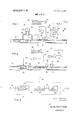
FIG. 1 is a partial pictorial and functional block diagram showing the measurement of gas flow utilizing an orifice meter and including the circuitry of the present invention for correcting for supercompressibility.
FIG. 2 is a partial pictorial and functional block diagram showing the circuitry utilized in computing gas flow utilizing a positive displacement meter and including the circuitry of the present invention for correcting the supercompressibility.
FIG. 3 is a functional block diagram of the circuitry for deriving the squared supercompressibility factor of the gas.
FIG. 4 is a functional block diagram of a summing and multiplying circuit for multiplying the squared supercompressibility factor by absolute pressure for use as a correction term in a gas flow computer.
FIG. 5 is a detailed electrical schematic diagram of one embodiment of the invention herein for deriving a signal representative of the correction factor for correcting gas flow computer measurements for supercompressibility.
DETAILED DESCRIPTION OF THE PREFERRED EMBODIMENTS In the measurement of gases, and most especially natural gases, the most common form of measurement is by utilizing orifice metering and the calculation of the flow rate of gas in standard units, i.e., standard cubic feet. A common form of the gas orifice flow equation is:
Qscr H A/ where:
Q the measured flow rate of the gas in standard units (standard cubic feet) C quasi-constant containing numerous factors includin g the supercompressibility factor F,,,, h differential pressure across the orifice plate opening T absolute temperature of the flowing gas P absolute pressure of the gas The orifice flow constant C may be defined as the rate of flow in cubic feet per hour, at base conditions, when the extension of the square root of h times P= 1. C is generally defined as follows:
ing of Natural Gas Gas Measurement Committee Report No. 3 (Rev. 1969), published by the American Gas Association, Inc. The values of F,,,, are more extensively defined over wide ranges of pressure and temperature in the Manual for the Determination of Supercompressibility Factors for Natural Gas" PAR Research Project NX-19 of the American Gas Association. However the values of F,,,, vary widely for varying combinations of pressure, temperature and specific gravity, and in practice an average factor is utilized which is only applicable for a given specific gravity, temperature and pressure.
It may be seen that the basic gas orifice flow equation could be rewritten as follows:
excluding F,,,, as a factor Q h, P and T are identical factors defined in equation (I) above.
Actual volume measurements made by turbine meters or positive displacement meters calculate volume measurements directly in actual cubic feet passing through the meter. Such actual volume measurements are converted to standard volume measurements by the following equation:
Qscr Q ACF( pv (5) where:
Q the measured flow rate of the gas in actual units (actual cubic feet) Qscp, P T and F,,,, are identical factors defined in equations l through (4) above.
By reviewing equations (4) and (5) above, it may be seen that the term which is common to the solution of the volume measurements in standard cubic feet in both equations is the term P F If this term could be derived in this form it may be used in the gas orifice flow equation and in the conversion of actual volume measurements made by positive displacement meters to standard volume measurements.
Therefore, the invention entails the computation of P f rather than a direct computation of F The reason for this is as above stated, in that P f,,,, is used in converting actual cubic feet measurements to standard cubic feet measurements. In addition, the squared function of F,,,, is not a handicap in orifice measurement, since it can be conveniently inserted into the gas flow computer and its square root extracted at the same time the square root is extracted of other variables in the flow equation. In addition, it makes computation of the factor F,,,, less critical.
Accordingly, the following equation was derived:
FWI=PIF(P)F(G)F(T)+KI (6) where:
P,=static gauge pressure of the flowing gas F(P) a predetermined pressure function, op-
timized for the selected operating ranges of pressure, temperature and specific gravity F(G) a predetermined gravity function, optimized for the selected operating ranges of pressure, temperature and specific gravity F( T) a predetermined temperature function, op-
timized for the selected operating ranges of pres- 5 sure, temperature and specific gravity X a predetermined constant, approximately unity, and optimized for the selected operating ranges of pressure, temperature and specific gravity.
To illustrate the derivation of the various functions of pressure, temperature and specific gravity that must be made for the selected range of pressure, temperature and specific gravity, an example will be utilized.
TABLE I F,,,, For Example Operating Ranges of T, P and G (Base) Average Specific Gravity 0.60 Pressure psi 30F 60F 90F F(P) is predetermined multiplying pressure function optimized for the range of pressure, temperature and specific gravity selected. For the range of values given above, and as shown in Table I, 60 F is the average temperature in the 30 to 90 F range. F(P) is then defined as the change in F,,,, per one psi change in pressure at the average specific gravity of 0.60 and the average temperature of 60 F. To determine F (P) over the 500-900 psi range selected, the values for the differences in F,,,, between 500-600 psi, between 600-700 psi, between 700-800 psi, and the difference between 800-900 psi would be averaged, and that average value determines F (P). Accordingly, F (P) may be calculated as follows:
Since F P) has been calculated at the average specific gravity and the average temperature over the range selected, we will, by definition, assign the value K, may now be calculated at the average pressure, 700 psi, of the range of pressures from 500 to 900 psi.
Substituting the appropriate values from Table 1 into equationfi) above, K may be calculated as follows:
The validity of the calculation of F( P) and K, may be checked at another pressure, say 500 psi, as follows:
The value in Table I for F,,,,, at 60 F at 500 psi is 1.0843, and the above calculated value differs from the actual value by approximately 0.03 percent, an acceptable deviation in gas flow measurement.
The values of F T) and F (G) may be calculated in a similar fashion to the above calculation for F P) by calculating the differences in F for discrete increments of change in temperature and specific gravity over the range of temperatures and specific gravity given.
However, another technique may be used to solve for F( T) or F(G). The following equation is basic equation of 1.0000 to F(G) and F(T) at the base or average specific gravity and temperature respectively. Accordingly, equation (6) may be expressed as follows:
transposing terms,
therefore, Fmay readily be calculated at any point as follows:
1n the example above, 60 F was the base temperature. Therefore, to calculate F(T) for 30F the appropriate 1%,, values may be extracted from Table 1,
and, using the previously calculated value of K Similarly, assuming 0.60 is the base gravity, F(G) may be calculated for other values of specific gravity by utilizing a formula similar to that shown above, as follows:
From the above, it is apparent that various values for F(P), F( T) and F(G) may be calculated for the preselected range of pressure, temperature and specific gravity under consideration.
Referring now to FIG. 1, a typical equipment setup for use in orifice metering of gas is shown. The gas is flowing in pipe 10 in the direction shown by the arrow and moves through a plate 12 having an orifice 14. A differential pressure transducer 16 is connected to both the upstream and downstream sides of the orifice plate 12 via tubing 18, 20, and 22, respectively, and generates an electrical signal representative of the differential pressure. The differential pressure signal is applied to gas flow computer 32 via conductor 52.
At the same time, the downstream static gauge pres sure of the gas is being measured by a static pressure transducer 26 connected to the downstream flow of the gas in pipe 10 via tubing 24 and 22. A temperature transducer 28, having a temperature probe 29 inserted into the gas flow, continuously monitors the temperature of the flowing gas and, via conventional transducer circuitry, generates an electrical signal representative of the temperature of the gas. The electrical signals representative of the static pressure measured by transducer 26 is applied via conductors 44 and 46 to a circuit 34 for calculating the squared value of supercompressibility (F and to an adding and multiplying circuit 36, respectively.
A second temperature transducer 30 having a probe 31 continuously monitoring the temperature of the flowing gas generates an electrical signal representative of the values of F T) over the range of temperature to be measured. This may be accomplished through conventional thermister circuitry and the electrical signal is applied via conductor 38 as an input to the supercompressibility factor circuit 34. The F,,,, output of circuit 34 is applied via conductor 40 to the adding and multiplying circuit 36.
Static pressure, P is converted to absolute pressure, P,,, by he addition of barometric pressure P in circuit 36. A signal representing barometric pressure P,, is applied to circuit 36 via conductor 56. Barometric pressure may be measured by any conventional means to derive a signal representative thereof. After the static pressure P has been converted to absolute pressure P,,, the absolute pressure is then multiplied by the applied input of F to generate an output equal to the absolute pressure multiplied by the squared value of the supercompressibility factor (P F which is then applied as an electrical input signal to the gas flow computer 32 via conductor 42. Utilizing well known computer technology, gas flow computer 32 utilizes the differential pressure signal applied via conductor 52, gas temperature signal applied in via conductor 50, and the value of P P applied in via 42, and with other preset values predetermined to define the orifice flow constant as shown in equation (2) above, the gas flow in standard units may be calculated. An electrical signal representative of the gas flow in standard units Q is generated and applied via conductor 54 to appropriate recording and display equipment (not shown).
in FIG. 2, gas is flowing in pipe in the direction shown by the arrow and is being metered by a gas turbine meter 60 having a rotor 62 that rotates axially as the gas flows through the meter and exerts force on the blades of the rotor. A detector 64 detects the number of rotations of rotor 62 and causes a series of discrete pulses to be induced in detector 64 and applied via conductor 66 to the gas flow computer 68. The number of pulses generated by turbine meter 60 and applied via conductor 66 are proportional to the actual quantity of gas moving through meter 60.
A static pressure transducer 70 monitors the pressure of the gas flowing in pipe 10 through tubing 72 and generates a signal proportional to the gauge pressure so measured and applied via conductor 82 as an input to circuit 78 for calculating the combined correction factor of absolute pressure multiplied by the squared value of the supercompressibility factor (P F A temperature transducer 74 having a temperature probe 75 injected into the gas stream continuously measures the temperature of the flowing gas and utilizing conventional circuitry, generates an electrical signal representative of the temperature of the gas applied via conductor 84 as another input to the gas flow computer 68.
A second temperature measuring device 76 having a probe 77 disposed in the gas flow for continuously monitoring the gas temperature utilizes conventional thermister circuitry to generate an electrical signal representative of F T) over the range of pressure, temperature and specific gravity selected. The electrical signal representative of F( T) is applied via conductor 80 as an input to the P F calculating circuit 78. A signal representing pressure P is applied via conductor 92 as another input to circuit 78 for converting static gauge pressure P to absolute pressure P as hereinabove previously described.
The P F F output of circuit 78 is applied via conductor 88 as an input to gas flow computer 68, where utilizing conventional computing technology and circuitry, the flow in actual cubic feet is converted to a standard measurement of flow, Q The standard volume measurement Q is represented by an electrical signal applied via conductor 96 to counting and/or visual display equipment (not shown).
FIGS. 3 and 4 are functional block diagrams of the F circuit 34 and the adding and multiplying circuit 36 shown in FIG. 1, and the P P circuit 78 is shown in FIG. 2. In FIG. 3, the F,,,, circuit 34 is shown in functional block schematic form with static pressure P being applied as an input via conductor 44 to an F P)F (G) multiplier 100. The multiplied output of circuit 100 is applied via conductor 109 as an input to the F( T) multiplier 102, with the variable input F( T) being applied as an input via conductors 38 from the F( T) transducer 30 (see FIG. 1). The multiplied output of circuit 102 is applied via conductor 110 to a summing circuit 104 in which the term K is added to the product of P F(P) F(G)F( T).
The calculated value of F is then applied via conductor 40 to a conventional analog multiplying circuit 114 within adding and multiplying circuit 36. Electrical signals representative of the static gauge pressure P are applied via conductor 46 as one input to a conventional summing circuit 112. The other' input of summing circuit 112 is an electrical signal representative of barometric pressure P applied via conductor 56. The summed barometric and static pressure values equal absolute pressure P,, and an electrical signal representative of P is applied via conductor 115 as an input to multiplying circuit 115 to be multiplied by the F input appfied via conductor 40. An output is generated at conductor 42 is equal to the product of absolute pressure times the square of the supercompressibility factor (P F FIG. is a detailed schematic diagram of the F,,,, circuit 34 and the adding and multiplying circuit 36 shown in FIG. 1, and represents the total circuitry of the P F 2 circuit 78 shown in FIG. 2. An electrical signal representative of static gauge pressure P is applied via conductors 44 and 116 as an input to the amplifier circuit 120 via resistor 119 (R and to the voltage divider network comprised of resistors 118 and 108, R and R respectively.
The circuit is designed for the average specific gravity to be set on the manual potentiometer 108 (R although specific gravity could be corrected automatically by use of a conventional function multiplier in place of potentiometer 108. The electrical signal proportional to static pressure P is multiplied by the gravity factor F (G) and F (P) by the proper selection of the values of resistors 119, 118, and 108, R R and R respectively. The value of resistors 121 determines the gain of amplifier 120.
The gravity factor F is of the form:
F(G) =F(G) 3.82G- 1.28
where:
F (G) function of gravity earlier defined in equation (6) G the specific gravity of the gas In FIG. 5, resistor 118 is sized to form a divider with potentiometer 108, R and R respectively, such that their division ratio is F (P) multiplied by 3.82. The gain of amplifier 120 is negative and is controlled by the ratio of resistors 119 and 121, resistor 121 having the value C F(P)R and C equal to 1.28. Accordingly the gain of amplifier 120 is shown by the following equation:
The resulting output of the multiplier circuit 100 via conductor 109 is:
V,...=3.82F(P)GP,-1.28F(P)P aq l fil fem Mai?) and substituting for F (G as defined in equation l0),
In multiplier circuit 102, the F( T) values are continuously variable and are applied via conductors 38 from a conventional thermistor transducer circuit 76 (see FIG. 2) and determines the gain of amplifier 122. Thus, the gain of amplifier 122 is directly controlled by the value of F( T), thereby multiplying the input product signal via conductor 109 by the temperature function F( T) which is applied out via conductor 110 as an input to the summing circuit 104. The product term P F(P)F(G)F(T) is added to the constant K, by means of a conventional operational amplifier summing circuit 126. The constant K is generated via a source voltage 123 and is preset by potentiometer 124(R The output of the summing circuit 104 via conductor 40 is F P F(P)F( G)F( T) K which is applied as one input to a conventional two-variable multiplying circuit 1 14. I
The signal representative of the static gauge pressure of the gas P is also applied via conductor 46 as an input to summing circuit 112. A signal representing pressure P is applied via conductor 92 as a second input to summing circuit 112. Summing circuit 112 is a conventional operational amplifier summing circuit for receiving the two inputs P and P and summing the two quantities to generate an electrical output representative of absolute pressure P applied via conductor as a second variable input to the multiplying circuit 114. The absolute pressure P,, and the F,,,, term are multiplied by the conventional multiplying circuit 114 which generates an electrical signal as an output applied via conductor 42 to a gas flow computer as shown in FIGS. 1 and 2 to accomplish the final calculation of gas flow in standard units.
While the detailed schematic portion of the various multiplying and adding circuits in FIG. 5 are further elaboration of the functional schematics shown in FIGS. 3 and 4, the P F circuit 78 as shown in FIG. 2 would include the identical circuitry shown in FIG. 5.
Numerous variations and modifications may obviously be made in the structure herein described without departing from the present invention. Accordingly, it should be clearly understood that the forms of the invention herein described and shown in the figures of the accompanying drawings are illustrative only and are not intended to limit the scope of the invention.
What is claimed is:
1. In apparatus for continuously determining the quantity of natural gas flowing in a pipeline over a preselected range of specific gravity, pressure and temperature utilizing a gas flow computer, the improvement therein for continuously correcting for the supercompressibility of the gas comprising measuring means for continuously measuring the static pressure of the gas and generating a first electrical signal in response thereto,
a first multiplying circuit for receiving said first electrical signal and multiplying said signal by predetermined functions of pressure and specific gravity for generating a second electrical signal representative of the product of said static pressure and said predetermined functions of pressure and specific gravity,
a second multiplying circuit for receiving said second electrical signal and multiplying said signal by a predetermined function of temperature and generating a third electrical signal representative of the product of said static pressure and said predetermined functions of pressure, specific gravity and temperature,
means for producing a fourth electrical signal representative of a first predetermined constant,
adding means for receiving said third and fourth electrical signals and summing said signals for producing a fifth electrical signal representative of the squared supercompressibility factor of the gas,
means for producing a sixth electrical signal representative of barometric pressure,
adding means for receiving and summing said first and sixth electrical signals representative of static pressure and barometric pressure and producing a seventh signal representative of absolute pressure, and
a third multiplying circuit for receiving said fifth and seventh signals representative of the squared supercompressibility factor and absolute pressure, multiplying said signals and generating an eighth electrical signal representative of the product of said absolute pressure and squared supercompressibility factor for application to the gas flow computer.
2. The apparatus as described in claim 1, wherein said first multiplying circuit includes an input voltage divider circuit for receiving said first electrical signal and including a first manual potentiometer, said first manual potentiometer adjustable for causing a voltage drop across said potentiometer representative of the average specific gravity of the natural gas over the preselected range of specific gravity, and
an amplifier circuit connected to said input voltage divider and receiving said first electrical signal, said voltage divider and amplifier circuits cooperating to multiply said first electrical signal by said preselected functions of pressure and gravity and generating said second signal.
3. The apparatus as described in claim 2, wherein said voltage divider has a division ratio equal to a second preselected constant multiplied by said preselected function of pressure.
4. The apparatus as described in claim 2, wherein said amplifier circuit has a gain equal to a third preselected constant multiplied by said preselected function of pressure.
5. The apparatus as described in claim 2, wherein said preselected function of specific gravity is equal to said second preselected constant multiplied by said average specific gravity value entered in said manual potentiometer plus said third preselected constant.
6. The apparatus as described in claim 1, wherein said second multiplying circuit includes an amplifier circuit having a gain varying in direct response to said predetermined function of temperature obtained by a temperature transducer circuit continuously monitoring the temperature of the gas flowing in the pipeline.
7. The apparatus as described in claim 1, wherein said adding means comprises a summing amplifier circuit.
8. The apparatus as described in claim 1, wherein said means for receiving and summing said first and sixth electrical signals representative of static pressure and barometric pressure comprises an input voltage divider network and a summing amplifier circuit.
9. A method of continuously determining a function of the supercompressibility factor of natural gas flowing in a pipeline over a preselected range of specific gravity, pressure and temperature, comprising the steps of measuring the continuous static pressure of the gas and generating an electrical signal representative thereof,
deriving predetermined functions of pressure, temperature and specific gravity over the preselected range of operation,
multiplying said signal representative of the static pressure of the gas by said predetermined functions of pressure, temperature and specific gravity for generating an electrical signal representative of the product P F(P)F( G)F( T),
generating an electrical signal representative of a predetermined constant factor valid for the preselected range of pressure, temperature and specific gravity, and
deriving an electrical signal representative of the squared supercompressibility factor of the gas equal to the signal representing the product P F( P)F (G)F (T plus the electrical repregentative of said derived predetermined constant.
10. The method as described in claim 9, including the further steps of generating an electrical signal representative of barometric pressure,
deriving an electrical signal representative of absolute pressure of the gas by summing said electrical signals representative of static pressure and barometric pressure, and
deriving an electrical signal representative of the product of said squared supercompressibility factor and said absolute pressure.
11. A method of continuously determining the value of the squared supercompressibility factor of natural gas flowing in a pipeline over a preselected range of specific gravity, pressure and temperature, comprising the steps of continuously measuring the static pressure of the flowing gas and generating a signal representative thereof, deriving functions of pressure, temperature and specific gravity over the preselected range of operation,
multiplying said signal representative of the static pressure of the gas by said derived functions of pressure, temperature and specific gravity for generating a signal representative of the product a deriving a constant factor related to the value of the squared supercompressibility factor of the gas at the average of the preselected range of specific gravity, pressure and temperature represented by the equation K, F P,F(P)F(G)F(T) and generating a signal representative thereof, and
deriving a signal representative of the squared supercompressibility factor of the gas equal to the sum of the signal representing said product P,F(P)F(G)F(T) and the signal representing said constant factor. 12. A method of continuously determining a function of the supercompressibility factor of natural gas flowing in a pipeline over a preselected range of specific gravity, pressure and temperature, comprising the steps of continuously measuring the static pressure of the flowing gas and generating a signal representative thereof,
deriving functions of pressure, temperature and specific gravity over the preselected range of operation,
multiplying said signal representative of the static pressure of the gas by said derived functions of pressure, temperature and specific gravity for generating a signal representative of the product )F( )F(T), deriving a constant factor related to the value of the squared supercompressibility factor of the gas at the average of the preselected range of specific gravity, pressure and temperature represented by the equation K, F P F(P)F(G)F(T) and generating a signal representative thereof, deriving a signal representative of the squared supercompressibility factor of the gas equal to the sum of the signal representing said product P ,F(P)F(G)F(T) and the signal representing said constant factor, continuously measuring barometric pressure and generating a signal representative thereof, deriving a signal representative of absolute pressure of the gas by summing said signals representative of static pressure of the gas and barometric pressure, and deriving a signal representative of the desired function of the supercompressibility factor by multiplying said signals representative of the squared supercompressibility factor and absolute pressure. 13. Apparatus for continuously determining a function of the supercompressibility factor of natural gas flowing in a pipeline over a preselected range of specific gravity, pressure and temperature, comprising means for continuously measuring the static pressure of the gas and generating a first signal in response thereto, means for continuously measuring the temperature of the gas and generating a second signal representative of a predetermined function of said measured temperature for the preselected ranges of specific gravity, pressure and temperature, first circuit means receiving said first and second signals and generating a third signal representative of the product of said first and second signals and predetermined functions of pressure and specific gravity for the preselected ranges of specific gravity, pressure and temperature, said third signal being representative of the product i means for generating a fourth signal representative of a constant factor related to the squared value of the supercompressibility factor of the gas at the average of the preselected ranges of specific gravity, pressure and temperature represented by the equation K F,,,, P,F(P)F(G)F(T), and second circuit means for summing said third and fourth signals and generating a fifth signal representative of the desired function of the supercompressibility factor of the gas. 14. The apparatus as described in claim 13, wherein said first circuit means comprises an input voltage divider circuit for receiving said first signal and including a manual potentiometer, said potentiometer adjustable to a resistive value representative of the average specific gravity of the natural gas, said voltage divider having a division ratio equal to a first preselected constant multiplied by said preselected function of pressure, an amplifier circuit having a gain equal to a second preselected constant multiplied by said predetermined function of pressure, said voltage divider and amplifier circuits cooperating to multiply said first signal representative of static pressure by said preselected functions of pressure and gravity, and
an amplifier circuit the gain of which varies in direct response to said second signal representative of said predetermined function of temperature.
15. Apparatus as described in claim 14, wherein said preselected function of gravity is equal to said first preselected constant multiplied by said average gravity resistive value entered in said manual potentiometer plus said second preselected constant.
16. The apparatus as described in claim 13, wherein said means for generating said fourth signal includes a source of positive dc voltage, and
a manual potentiometer connected to said source of positive dc voltage for adjusting the voltage drop across the potentiometer to equal said constant factor.
17. The apparatus as described in claim 13, wherein said second circuit means comprises a summing amplifier for receiving and summing said third and fourth signals.
18. The apparatus as described in claim 13, further including means for continuously measuring barometric pressure and generating a sixth signal in response thereto,
means for receiving said first and sixth signals representative of said static pressure of the gas and barometric pressure and summing said signals to produce a seventh signal representative of the absolute pressure of the gas, and
third circuit means receiving said fifth and seventh signals and generating an eighth signal representative of the desired function of the squared supercompressibility factor obtained as a product of said fifth and seventh signals.
19. The apparatus as described in claim 18, wherein said means for receiving and summing said first and sixth electrical signals comprises a summing amplifier circuit.
20. Apparatus for continuously determining a function of the squared supercornpressibility factor of natural gas flowing in a pipeline over a preselected range of specific gravity, pressure and temperature, comprising means for continuously measuring the static pressure of the gas and generating a first signal in response thereto,
means for continuously measuring the temperature of the gas and generating a second signal representative of a predetermined function of said measured temperature for the preselected ranges of specific gravity, pressure and temperature,
first circuit means receiving said first and second signals and generating a third signal representative of the product of said first and second signals and predetermined functions of pressure and specific gravity for the preselected ranges of specific gravity, pressure and temperature, said third signal being representative of the product i means for generating a fourth signal representative of a constant factor related to the squared value of the supercompressibility factor of the gas at the representative of said static pressure of the gas and barometric pressure and summing said signals to produce a seventh signal representative of the ab solute pressure of the gas, and
third circuit means receiving said fifth and seventh signals and generating an eighth signal representative of the desired function of the squared supercompressibility factor obtained as a product of said fifth and seventh signals.
Claims (20)
1. In apparatus for continuously determining the quantity of natural gas flowing in a pipeline over a preselected range of specific gravity, pressure and temperature utilizing a gas flow computer, the improvement therein for continuously correcting for the supercompressibility of the gas comprising measuring means for continuously measuring the static pressure of the gas and generating a first electrical signal in response thereto, a first multiplying circuit for receiving said first electrical signal and multiplying said signal by predetermined functions of pressure and specific gravity for generating a second electrical signal representative of the product of said static pressure and said predetermined functions of pressure and specific gravity, a second multiplying circuit for receiving said second electrical signal and multiplying said signal by a predetermined function of temperature and generating a third electrical signal representative of the product of said static pressure and said predetermined functions of pressure, specific gravity and temperature, means for producing a fourth electrical signal representative of a first predetermined constant, adding means for receiving said third and fourth electrical signals and summing said signals for producing a fifth electrical signal representative of the squared supercompressibility factor of the gas, means for producing a sixth electrical signal representative of barometric pressure, adding means for receiving and summing said first and sixth electrical signals representative of static pressure and barometric pressure and producing a seventh signal representative of absolute pressure, and a third multiplying circuit for receiving said fifth and seventh signals representative of the squared supercompressibility factor and absolute pressure, multiplying said signals and generating an eighth electrical signal representative of the product of said absolute pressure and squared supercompressibility factor for application to the gas flow computer.
2. The apparatus as described in claim 1, wherein said first multiplying circuit includes an input voltage divider circuit for receiving said first electrical signal and including a first manual potentiometer, said first manual potentiometer adjustable for causing a voltage drop across said potentiometer representative of the average specific gravity of the natural gas over the preselected range of specific gravity, and an amplifier circuit connected to said input voltage divider and receiving said first electrical signal, said voltage divider and amplifier circuits cooperating to multiply said first electrical signal by said preselected functions of pressure and gravity and generating said second signal.
3. The apparatus as described in claim 2, wherein said voltage divider has a division ratio equal to a second preselected constant multiplied by said preselected function of pressure.
4. The apparatus as described in claim 2, wherein said amplifier circuit has a gain equal to a third preselected constant multiplied by said preselected function of pressure.
5. The apparatus as described in claim 2, wherein said preselected function of specific gravity is equal to said seCond preselected constant multiplied by said average specific gravity value entered in said manual potentiometer plus said third preselected constant.
6. The apparatus as described in claim 1, wherein said second multiplying circuit includes an amplifier circuit having a gain varying in direct response to said predetermined function of temperature obtained by a temperature transducer circuit continuously monitoring the temperature of the gas flowing in the pipeline.
7. The apparatus as described in claim 1, wherein said adding means comprises a summing amplifier circuit.
8. The apparatus as described in claim 1, wherein said means for receiving and summing said first and sixth electrical signals representative of static pressure and barometric pressure comprises an input voltage divider network and a summing amplifier circuit.
9. A method of continuously determining a function of the supercompressibility factor of natural gas flowing in a pipeline over a preselected range of specific gravity, pressure and temperature, comprising the steps of measuring the continuous static pressure of the gas and generating an electrical signal representative thereof, deriving predetermined functions of pressure, temperature and specific gravity over the preselected range of operation, multiplying said signal representative of the static pressure of the gas by said predetermined functions of pressure, temperature and specific gravity for generating an electrical signal representative of the product PSF(P)F(G)F(T), generating an electrical signal representative of a predetermined constant factor valid for the preselected range of pressure, temperature and specific gravity, and deriving an electrical signal representative of the squared supercompressibility factor of the gas equal to the signal representing the product PSF(P)F(G)F(T) plus the electrical signal representative of said derived predetermined constant.
10. The method as described in claim 9, including the further steps of generating an electrical signal representative of barometric pressure, deriving an electrical signal representative of absolute pressure of the gas by summing said electrical signals representative of static pressure and barometric pressure, and deriving an electrical signal representative of the product of said squared supercompressibility factor and said absolute pressure.
11. A method of continuously determining the value of the squared supercompressibility factor of natural gas flowing in a pipeline over a preselected range of specific gravity, pressure and temperature, comprising the steps of continuously measuring the static pressure of the flowing gas and generating a signal representative thereof, deriving functions of pressure, temperature and specific gravity over the preselected range of operation, multiplying said signal representative of the static pressure of the gas by said derived functions of pressure, temperature and specific gravity for generating a signal representative of the product PsF(P)F(G)F(T), deriving a constant factor related to the value of the squared supercompressibility factor of the gas at the average of the preselected range of specific gravity, pressure and temperature represented by the equation K1 Fpv2 - PsF(P)F(G)F(T) and generating a signal representative thereof, and deriving a signal representative of the squared supercompressibility factor of the gas equal to the sum of the signal representing said product PsF(P)F(G)F(T) and the signal representing said constant factor.
12. A method of continuously determining a function of the supercompressibility factor of natural gas flowing in a pipeline over a preselected range of specific gravity, pressure and temperature, comprising the steps of continuously measuring the static pressUre of the flowing gas and generating a signal representative thereof, deriving functions of pressure, temperature and specific gravity over the preselected range of operation, multiplying said signal representative of the static pressure of the gas by said derived functions of pressure, temperature and specific gravity for generating a signal representative of the product PsF(P)F(G)F(T), deriving a constant factor related to the value of the squared supercompressibility factor of the gas at the average of the preselected range of specific gravity, pressure and temperature represented by the equation K1 Fpv2 - PsF(P)F(G)F(T) and generating a signal representative thereof, deriving a signal representative of the squared supercompressibility factor of the gas equal to the sum of the signal representing said product PsF(P)F(G)F(T) and the signal representing said constant factor, continuously measuring barometric pressure and generating a signal representative thereof, deriving a signal representative of absolute pressure of the gas by summing said signals representative of static pressure of the gas and barometric pressure, and deriving a signal representative of the desired function of the supercompressibility factor by multiplying said signals representative of the squared supercompressibility factor and absolute pressure.
13. Apparatus for continuously determining a function of the supercompressibility factor of natural gas flowing in a pipeline over a preselected range of specific gravity, pressure and temperature, comprising means for continuously measuring the static pressure of the gas and generating a first signal in response thereto, means for continuously measuring the temperature of the gas and generating a second signal representative of a predetermined function of said measured temperature for the preselected ranges of specific gravity, pressure and temperature, first circuit means receiving said first and second signals and generating a third signal representative of the product of said first and second signals and predetermined functions of pressure and specific gravity for the preselected ranges of specific gravity, pressure and temperature, said third signal being representative of the product PsF(P)F(G)F(T), means for generating a fourth signal representative of a constant factor related to the squared value of the supercompressibility factor of the gas at the average of the preselected ranges of specific gravity, pressure and temperature represented by the equation K1 Fpv2 -PsF(P)F(G)F(T), and second circuit means for summing said third and fourth signals and generating a fifth signal representative of the desired function of the supercompressibility factor of the gas.
14. The apparatus as described in claim 13, wherein said first circuit means comprises an input voltage divider circuit for receiving said first signal and including a manual potentiometer, said potentiometer adjustable to a resistive value representative of the average specific gravity of the natural gas, said voltage divider having a division ratio equal to a first preselected constant multiplied by said preselected function of pressure, an amplifier circuit having a gain equal to a second preselected constant multiplied by said predetermined function of pressure, said voltage divider and amplifier circuits cooperating to multiply said first signal representative of static pressure by said preselected functions of pressure and gravity, and an amplifier circuit the gain of which varies in direct response to said second signal representative of said predetermined function of temperature.
15. Apparatus as described in claim 14, wherein said preselected function of gravity is equal to said first preselected constant multiplied by said average gravity resistive value entered in said manual potentIometer plus said second preselected constant.
16. The apparatus as described in claim 13, wherein said means for generating said fourth signal includes a source of positive dc voltage, and a manual potentiometer connected to said source of positive dc voltage for adjusting the voltage drop across the potentiometer to equal said constant factor.
17. The apparatus as described in claim 13, wherein said second circuit means comprises a summing amplifier for receiving and summing said third and fourth signals.
18. The apparatus as described in claim 13, further including means for continuously measuring barometric pressure and generating a sixth signal in response thereto, means for receiving said first and sixth signals representative of said static pressure of the gas and barometric pressure and summing said signals to produce a seventh signal representative of the absolute pressure of the gas, and third circuit means receiving said fifth and seventh signals and generating an eighth signal representative of the desired function of the squared supercompressibility factor obtained as a product of said fifth and seventh signals.
19. The apparatus as described in claim 18, wherein said means for receiving and summing said first and sixth electrical signals comprises a summing amplifier circuit.
20. Apparatus for continuously determining a function of the squared supercompressibility factor of natural gas flowing in a pipeline over a preselected range of specific gravity, pressure and temperature, comprising means for continuously measuring the static pressure of the gas and generating a first signal in response thereto, means for continuously measuring the temperature of the gas and generating a second signal representative of a predetermined function of said measured temperature for the preselected ranges of specific gravity, pressure and temperature, first circuit means receiving said first and second signals and generating a third signal representative of the product of said first and second signals and predetermined functions of pressure and specific gravity for the preselected ranges of specific gravity, pressure and temperature, said third signal being representative of the product PsF(P)F(G)F(T), means for generating a fourth signal representative of a constant factor related to the squared value of the supercompressibility factor of the gas at the average of the preselected ranges of specific gravity, pressure and temperature represented by the equation K1 Fpv2 -PsF(P)F(G)F(T), second circuit means for summing said third and fourth signals and generating a fifth signal representative of the squared supercompressibility factor of the gas, means for continuously measuring barometric pressure and generating a sixth signal in response thereto, means for receiving said first and sixth signals representative of said static pressure of the gas and barometric pressure and summing said signals to produce a seventh signal representative of the absolute pressure of the gas, and third circuit means receiving said fifth and seventh signals and generating an eighth signal representative of the desired function of the squared supercompressibility factor obtained as a product of said fifth and seventh signals.
Applications Claiming Priority (1)
| Application Number | Priority Date | Filing Date | Title |
|---|---|---|---|
| US2060670A | 1970-03-18 | 1970-03-18 |
Publications (1)
| Publication Number | Publication Date |
|---|---|
| US3701280A true US3701280A (en) | 1972-10-31 |
Family
ID=21799562
Family Applications (1)
| Application Number | Title | Priority Date | Filing Date |
|---|---|---|---|
| US20606A Expired - Lifetime US3701280A (en) | 1970-03-18 | 1970-03-18 | Method and apparatus for determining the supercompressibility factor of natural gas |
Country Status (5)
| Country | Link |
|---|---|
| US (1) | US3701280A (en) |
| CA (1) | CA922541A (en) |
| DE (1) | DE2113151A1 (en) |
| FR (1) | FR2084773A5 (en) |
| GB (1) | GB1317344A (en) |
Cited By (134)
| Publication number | Priority date | Publication date | Assignee | Title |
|---|---|---|---|---|
| US3752393A (en) * | 1971-08-02 | 1973-08-14 | Teledyne Ind | Digital flow calculator |
| US4063824A (en) * | 1975-08-05 | 1977-12-20 | E. I. Du Pont De Nemours And Company | Chemical dosimeter having a constant flow air sampling pump |
| US4123932A (en) * | 1977-05-25 | 1978-11-07 | E. I. Du Pont De Nemours And Company | Dosimeter for monitoring working areas |
| US4173891A (en) * | 1978-01-12 | 1979-11-13 | Rockwell International Corporation | Method and apparatus for measuring gas flow |
| DE2939721A1 (en) * | 1978-10-02 | 1980-04-10 | Dresser Ind | DEVICE AND METHOD FOR CORRECTING A GAS VOLUME IN THE EVENT OF PRESSURE AND / OR TEMPERATURE VARIATIONS |
| US4269059A (en) * | 1979-03-19 | 1981-05-26 | E. I. Du Pont De Nemours And Company | Dosimeter having constant flow pump |
| US4337668A (en) * | 1980-12-05 | 1982-07-06 | Sun Gas Company | Orifice wear compensation |
| US4390956A (en) * | 1981-03-06 | 1983-06-28 | The Singer Company | Apparatus for correcting measured gas flow |
| US4419898A (en) * | 1980-10-17 | 1983-12-13 | Sarasota Automation Limited | Method and apparatus for determining the mass flow of a fluid |
| US4476708A (en) * | 1982-11-12 | 1984-10-16 | Thoratec Laboratories Corporation | Flow controller |
| US4489592A (en) * | 1983-02-22 | 1984-12-25 | Uop Inc. | Density monitor and method |
| US4562744A (en) * | 1984-05-04 | 1986-01-07 | Precision Measurement, Inc. | Method and apparatus for measuring the flowrate of compressible fluids |
| US4581707A (en) * | 1980-05-30 | 1986-04-08 | John Millar (U.K.) Limited | Microprocessor controlled valve flow indicators |
| US4584868A (en) * | 1985-05-16 | 1986-04-29 | American Meter Company | Apparatus for determining the supercompressibility factor of a flowing gas |
| US4646940A (en) * | 1984-05-16 | 1987-03-03 | Northern Indiana Public Service Company | Method and apparatus for accurately measuring volume of gas flowing as a result of differential pressure |
| US4677841A (en) * | 1984-04-05 | 1987-07-07 | Precision Measurement, Inc. | Method and apparatus for measuring the relative density of gases |
| EP0236681A2 (en) * | 1986-02-05 | 1987-09-16 | M & FC HOLDING COMPANY, INC. | Method and apparatus for measuring and providing corrected gas flow |
| US4967603A (en) * | 1987-10-15 | 1990-11-06 | Kernforschungszentrum Karlsruhe Gmbh | Inductive flow probe for measuring the flow velocity of a stream of liquid metal |
| US5046369A (en) * | 1989-04-11 | 1991-09-10 | Halliburton Company | Compensated turbine flowmeter |
| US5106294A (en) * | 1988-04-16 | 1992-04-21 | Conel Ag | Method and arrangement for reducing the effect of disturbances on the combustion of a fan burner system |
| US5237852A (en) * | 1992-03-23 | 1993-08-24 | Atlantic Richfield Company | Measurement of gas properties |
| US5307668A (en) * | 1992-10-05 | 1994-05-03 | Badger Meter, Inc. | Gas density meter and method |
| US5323657A (en) * | 1991-11-04 | 1994-06-28 | Badger Meter, Inc. | Volumetric flow corrector and method |
| US5445035A (en) * | 1991-12-18 | 1995-08-29 | Delajoud; Pierre R. | Precision gas mass flow measurement apparatus and method maintaining constant fluid temperature in thin elongated flow path |
| US5495769A (en) * | 1993-09-07 | 1996-03-05 | Rosemount Inc. | Multivariable transmitter |
| US5551282A (en) * | 1995-03-20 | 1996-09-03 | Badger Meter, Inc. | Method and apparatus for measuring volume correction using molar quantities |
| US5570300A (en) * | 1992-04-22 | 1996-10-29 | The Foxboro Company | Self-validating sensors |
| US5606513A (en) * | 1993-09-20 | 1997-02-25 | Rosemount Inc. | Transmitter having input for receiving a process variable from a remote sensor |
| US5707150A (en) * | 1995-09-19 | 1998-01-13 | Rosemount Analytical Inc. | Apparatus for computing BTU content in a sample of gas |
| US5774378A (en) * | 1993-04-21 | 1998-06-30 | The Foxboro Company | Self-validating sensors |
| US5828567A (en) * | 1996-11-07 | 1998-10-27 | Rosemount Inc. | Diagnostics for resistance based transmitter |
| US5956663A (en) * | 1996-11-07 | 1999-09-21 | Rosemount, Inc. | Signal processing technique which separates signal components in a sensor for sensor diagnostics |
| US6017143A (en) * | 1996-03-28 | 2000-01-25 | Rosemount Inc. | Device in a process system for detecting events |
| EP0977021A1 (en) * | 1996-01-05 | 2000-02-02 | Waldner Laboreinrichtungen GmbH & Co. | Method for measuring a fluid flow in a flow channel |
| US6029527A (en) * | 1997-04-02 | 2000-02-29 | Wagner International Ag | Fluid flow rate measuring and controlling device and method |
| US6047220A (en) * | 1996-12-31 | 2000-04-04 | Rosemount Inc. | Device in a process system for validating a control signal from a field device |
| US6298454B1 (en) | 1999-02-22 | 2001-10-02 | Fisher-Rosemount Systems, Inc. | Diagnostics in a process control system |
| US6356191B1 (en) | 1999-06-17 | 2002-03-12 | Rosemount Inc. | Error compensation for a process fluid temperature transmitter |
| US6370448B1 (en) | 1997-10-13 | 2002-04-09 | Rosemount Inc. | Communication technique for field devices in industrial processes |
| US6434504B1 (en) | 1996-11-07 | 2002-08-13 | Rosemount Inc. | Resistance based process control device diagnostics |
| US6449574B1 (en) | 1996-11-07 | 2002-09-10 | Micro Motion, Inc. | Resistance based process control device diagnostics |
| US6457367B1 (en) | 1999-09-28 | 2002-10-01 | Rosemount Inc. | Scalable process transmitter |
| US6473710B1 (en) | 1999-07-01 | 2002-10-29 | Rosemount Inc. | Low power two-wire self validating temperature transmitter |
| US6480131B1 (en) | 2000-08-10 | 2002-11-12 | Rosemount Inc. | Multiple die industrial process control transmitter |
| US6487912B1 (en) | 1999-09-28 | 2002-12-03 | Rosemount Inc. | Preinstallation of a pressure sensor module |
| US6504489B1 (en) | 2000-05-15 | 2003-01-07 | Rosemount Inc. | Process control transmitter having an externally accessible DC circuit common |
| US6505517B1 (en) | 1999-07-23 | 2003-01-14 | Rosemount Inc. | High accuracy signal processing for magnetic flowmeter |
| US6510740B1 (en) | 1999-09-28 | 2003-01-28 | Rosemount Inc. | Thermal management in a pressure transmitter |
| US6511337B1 (en) | 1999-09-28 | 2003-01-28 | Rosemount Inc. | Environmentally sealed instrument loop adapter |
| US6519546B1 (en) | 1996-11-07 | 2003-02-11 | Rosemount Inc. | Auto correcting temperature transmitter with resistance based sensor |
| US6516672B2 (en) | 2001-05-21 | 2003-02-11 | Rosemount Inc. | Sigma-delta analog to digital converter for capacitive pressure sensor and process transmitter |
| US6539267B1 (en) | 1996-03-28 | 2003-03-25 | Rosemount Inc. | Device in a process system for determining statistical parameter |
| US6546805B2 (en) | 2000-03-07 | 2003-04-15 | Rosemount Inc. | Process fluid transmitter with an environmentally sealed service block |
| US6556145B1 (en) | 1999-09-24 | 2003-04-29 | Rosemount Inc. | Two-wire fluid temperature transmitter with thermocouple diagnostics |
| US6571132B1 (en) | 1999-09-28 | 2003-05-27 | Rosemount Inc. | Component type adaptation in a transducer assembly |
| US6601005B1 (en) | 1996-11-07 | 2003-07-29 | Rosemount Inc. | Process device diagnostics using process variable sensor signal |
| US6611775B1 (en) | 1998-12-10 | 2003-08-26 | Rosemount Inc. | Electrode leakage diagnostics in a magnetic flow meter |
| US6615149B1 (en) | 1998-12-10 | 2003-09-02 | Rosemount Inc. | Spectral diagnostics in a magnetic flow meter |
| US6629059B2 (en) | 2001-05-14 | 2003-09-30 | Fisher-Rosemount Systems, Inc. | Hand held diagnostic and communication device with automatic bus detection |
| US6633782B1 (en) | 1999-02-22 | 2003-10-14 | Fisher-Rosemount Systems, Inc. | Diagnostic expert in a process control system |
| US6643610B1 (en) | 1999-09-24 | 2003-11-04 | Rosemount Inc. | Process transmitter with orthogonal-polynomial fitting |
| US6654697B1 (en) | 1996-03-28 | 2003-11-25 | Rosemount Inc. | Flow measurement with diagnostics |
| US6662662B1 (en) | 2000-05-04 | 2003-12-16 | Rosemount, Inc. | Pressure transmitter with improved isolator system |
| US6684711B2 (en) | 2001-08-23 | 2004-02-03 | Rosemount Inc. | Three-phase excitation circuit for compensated capacitor industrial process control transmitters |
| US6701274B1 (en) | 1999-08-27 | 2004-03-02 | Rosemount Inc. | Prediction of error magnitude in a pressure transmitter |
| US6735484B1 (en) | 2000-09-20 | 2004-05-11 | Fargo Electronics, Inc. | Printer with a process diagnostics system for detecting events |
| US6754601B1 (en) | 1996-11-07 | 2004-06-22 | Rosemount Inc. | Diagnostics for resistive elements of process devices |
| US6765968B1 (en) | 1999-09-28 | 2004-07-20 | Rosemount Inc. | Process transmitter with local databus |
| US6772036B2 (en) | 2001-08-30 | 2004-08-03 | Fisher-Rosemount Systems, Inc. | Control system using process model |
| US6907383B2 (en) | 1996-03-28 | 2005-06-14 | Rosemount Inc. | Flow diagnostic system |
| US6920799B1 (en) | 2004-04-15 | 2005-07-26 | Rosemount Inc. | Magnetic flow meter with reference electrode |
| US6970003B2 (en) | 2001-03-05 | 2005-11-29 | Rosemount Inc. | Electronics board life prediction of microprocessor-based transmitters |
| US20050284227A1 (en) * | 2004-06-25 | 2005-12-29 | Broden David A | High temperature pressure transmitter assembly |
| US7010459B2 (en) | 1999-06-25 | 2006-03-07 | Rosemount Inc. | Process device diagnostics using process variable sensor signal |
| US7018800B2 (en) | 2003-08-07 | 2006-03-28 | Rosemount Inc. | Process device with quiescent current diagnostics |
| US20060095394A1 (en) * | 1996-03-28 | 2006-05-04 | Miller John P | Rule set for root cause diagnostics |
| US7046180B2 (en) | 2004-04-21 | 2006-05-16 | Rosemount Inc. | Analog-to-digital converter with range error detection |
| US7085610B2 (en) | 1996-03-28 | 2006-08-01 | Fisher-Rosemount Systems, Inc. | Root cause diagnostics |
| US7109883B2 (en) | 2002-09-06 | 2006-09-19 | Rosemount Inc. | Low power physical layer for a bus in an industrial transmitter |
| US20060224334A1 (en) * | 2005-02-25 | 2006-10-05 | Ruihong Zhang | Precision gas flow meter |
| US20060236781A1 (en) * | 2003-07-03 | 2006-10-26 | Fujikin Incorporated | Differential pressure type flowmeter and differential pressure type flowmeter controller |
| US7134354B2 (en) | 1999-09-28 | 2006-11-14 | Rosemount Inc. | Display for process transmitter |
| US7206646B2 (en) | 1999-02-22 | 2007-04-17 | Fisher-Rosemount Systems, Inc. | Method and apparatus for performing a function in a plant using process performance monitoring with process equipment monitoring and control |
| US7221988B2 (en) | 2001-03-01 | 2007-05-22 | Rosemount, Inc. | Creation and display of indices within a process plant |
| US7254518B2 (en) | 1996-03-28 | 2007-08-07 | Rosemount Inc. | Pressure transmitter with diagnostics |
| US7272531B2 (en) | 2005-09-20 | 2007-09-18 | Fisher-Rosemount Systems, Inc. | Aggregation of asset use indices within a process plant |
| US7290450B2 (en) | 2003-07-18 | 2007-11-06 | Rosemount Inc. | Process diagnostics |
| US7321846B1 (en) | 2006-10-05 | 2008-01-22 | Rosemount Inc. | Two-wire process control loop diagnostics |
| US20080053242A1 (en) * | 2006-08-29 | 2008-03-06 | Schumacher Mark S | Process device with density measurement |
| US7346404B2 (en) | 2001-03-01 | 2008-03-18 | Fisher-Rosemount Systems, Inc. | Data sharing in a process plant |
| US20080133700A1 (en) * | 1996-08-20 | 2008-06-05 | Invensys Systems, Inc. | Control system apparatus and systems using value-based transfers |
| US7525419B2 (en) | 2006-01-30 | 2009-04-28 | Rosemount Inc. | Transmitter with removable local operator interface |
| US7523667B2 (en) | 2003-12-23 | 2009-04-28 | Rosemount Inc. | Diagnostics of impulse piping in an industrial process |
| US7557702B2 (en) | 1999-02-22 | 2009-07-07 | Evren Eryurek | Integrated alert generation in a process plant |
| US7562135B2 (en) | 2000-05-23 | 2009-07-14 | Fisher-Rosemount Systems, Inc. | Enhanced fieldbus device alerts in a process control system |
| US7590511B2 (en) | 2007-09-25 | 2009-09-15 | Rosemount Inc. | Field device for digital process control loop diagnostics |
| US20090292484A1 (en) * | 2008-05-23 | 2009-11-26 | Wiklund David E | Multivariable process fluid flow device with energy flow calculation |
| US7627441B2 (en) | 2003-09-30 | 2009-12-01 | Rosemount Inc. | Process device with vibration based diagnostics |
| US7630861B2 (en) | 1996-03-28 | 2009-12-08 | Rosemount Inc. | Dedicated process diagnostic device |
| US7702401B2 (en) | 2007-09-05 | 2010-04-20 | Fisher-Rosemount Systems, Inc. | System for preserving and displaying process control data associated with an abnormal situation |
| US7750642B2 (en) | 2006-09-29 | 2010-07-06 | Rosemount Inc. | Magnetic flowmeter with verification |
| US7761923B2 (en) | 2004-03-01 | 2010-07-20 | Invensys Systems, Inc. | Process control methods and apparatus for intrusion detection, protection and network hardening |
| US7773715B2 (en) | 2002-09-06 | 2010-08-10 | Rosemount Inc. | Two wire transmitter with isolated can output |
| US7860857B2 (en) | 2006-03-30 | 2010-12-28 | Invensys Systems, Inc. | Digital data processing apparatus and methods for improving plant performance |
| US7890927B2 (en) | 1999-05-17 | 2011-02-15 | Invensys Systems, Inc. | Apparatus and method for configuring and editing a control system with live data |
| US20110082568A1 (en) * | 2009-10-01 | 2011-04-07 | Schulte John P | Process device with sampling skew |
| US7921734B2 (en) | 2009-05-12 | 2011-04-12 | Rosemount Inc. | System to detect poor process ground connections |
| US7940189B2 (en) | 2005-09-29 | 2011-05-10 | Rosemount Inc. | Leak detector for process valve |
| US7949495B2 (en) | 1996-03-28 | 2011-05-24 | Rosemount, Inc. | Process variable transmitter with diagnostics |
| US7953501B2 (en) | 2006-09-25 | 2011-05-31 | Fisher-Rosemount Systems, Inc. | Industrial process control loop monitor |
| US8005647B2 (en) | 2005-04-08 | 2011-08-23 | Rosemount, Inc. | Method and apparatus for monitoring and performing corrective measures in a process plant using monitoring data with corrective measures data |
| US8055479B2 (en) | 2007-10-10 | 2011-11-08 | Fisher-Rosemount Systems, Inc. | Simplified algorithm for abnormal situation prevention in load following applications including plugged line diagnostics in a dynamic process |
| US8073967B2 (en) | 2002-04-15 | 2011-12-06 | Fisher-Rosemount Systems, Inc. | Web services-based communications for use with process control systems |
| US8090452B2 (en) | 1999-06-11 | 2012-01-03 | Invensys Systems, Inc. | Methods and apparatus for control using control devices that provide a virtual machine environment and that communicate via an IP network |
| US8112565B2 (en) | 2005-06-08 | 2012-02-07 | Fisher-Rosemount Systems, Inc. | Multi-protocol field device interface with automatic bus detection |
| US8127060B2 (en) | 2009-05-29 | 2012-02-28 | Invensys Systems, Inc | Methods and apparatus for control configuration with control objects that are fieldbus protocol-aware |
| US8290721B2 (en) | 1996-03-28 | 2012-10-16 | Rosemount Inc. | Flow measurement diagnostics |
| US8301676B2 (en) | 2007-08-23 | 2012-10-30 | Fisher-Rosemount Systems, Inc. | Field device with capability of calculating digital filter coefficients |
| US8334788B2 (en) | 2010-03-04 | 2012-12-18 | Rosemount Inc. | Process variable transmitter with display |
| US8368640B2 (en) | 1999-05-17 | 2013-02-05 | Invensys Systems, Inc. | Process control configuration system with connection validation and configuration |
| US8417595B2 (en) | 2001-03-01 | 2013-04-09 | Fisher-Rosemount Systems, Inc. | Economic calculations in a process control system |
| US8463964B2 (en) | 2009-05-29 | 2013-06-11 | Invensys Systems, Inc. | Methods and apparatus for control configuration with enhanced change-tracking |
| US8594814B2 (en) | 2008-06-20 | 2013-11-26 | Invensys Systems, Inc. | Systems and methods for immersive interaction with actual and/or simulated facilities for process, environmental and industrial control |
| US8788070B2 (en) | 2006-09-26 | 2014-07-22 | Rosemount Inc. | Automatic field device service adviser |
| US8898036B2 (en) | 2007-08-06 | 2014-11-25 | Rosemount Inc. | Process variable transmitter with acceleration sensor |
| US9052240B2 (en) | 2012-06-29 | 2015-06-09 | Rosemount Inc. | Industrial process temperature transmitter with sensor stress diagnostics |
| US9121743B2 (en) | 2012-05-31 | 2015-09-01 | Rosemount Inc. | Process variable transmitter system with analog communication |
| US9201420B2 (en) | 2005-04-08 | 2015-12-01 | Rosemount, Inc. | Method and apparatus for performing a function in a process plant using monitoring data with criticality evaluation data |
| US9207129B2 (en) | 2012-09-27 | 2015-12-08 | Rosemount Inc. | Process variable transmitter with EMF detection and correction |
| US9207670B2 (en) | 2011-03-21 | 2015-12-08 | Rosemount Inc. | Degrading sensor detection implemented within a transmitter |
| US20150369716A1 (en) * | 2014-06-23 | 2015-12-24 | Caterpillar Inc. | System and Method for Determining the Specific Gravity of a Gaseous Fuel |
| US9602122B2 (en) | 2012-09-28 | 2017-03-21 | Rosemount Inc. | Process variable measurement noise diagnostic |
| US9927788B2 (en) | 2011-05-19 | 2018-03-27 | Fisher-Rosemount Systems, Inc. | Software lockout coordination between a process control system and an asset management system |
| US11231313B2 (en) * | 2017-04-18 | 2022-01-25 | Tokyo Electron Limited | Method of obtaining output flow rate of flow rate controller and method of processing workpiece |
Families Citing this family (5)
| Publication number | Priority date | Publication date | Assignee | Title |
|---|---|---|---|---|
| FI81447C (en) * | 1987-09-15 | 1990-10-10 | Ilmaterae Oy | ANALYZING FOLLOWING VOLUME IN BLAESTER. |
| US5237523A (en) * | 1990-07-25 | 1993-08-17 | Honeywell Inc. | Flowmeter fluid composition and temperature correction |
| US5201581A (en) * | 1991-11-18 | 1993-04-13 | Badger Meter, Inc. | Method and apparatus for measuring mass flow and energy content using a linear flow meter |
| DE102007030700A1 (en) * | 2007-06-30 | 2009-05-07 | Endress + Hauser Flowtec Ag | Measuring system for a medium flowing in a process line |
| US8447536B2 (en) | 2007-06-30 | 2013-05-21 | Endress + Hauser Flowtec Ag | Medium density measuring system |
Citations (3)
| Publication number | Priority date | Publication date | Assignee | Title |
|---|---|---|---|---|
| US3248942A (en) * | 1961-01-10 | 1966-05-03 | Jr Howard W Cole | Flowmeter with specific gravity compensator |
| US3537312A (en) * | 1968-06-21 | 1970-11-03 | Westwind Turbines Ltd | Mass flow measuring apparatus |
| US3555901A (en) * | 1968-09-27 | 1971-01-19 | Camco Inc | Method of and apparatus for measuring varying fluid flow |
-
1970
- 1970-03-18 US US20606A patent/US3701280A/en not_active Expired - Lifetime
-
1971
- 1971-02-01 CA CA104171A patent/CA922541A/en not_active Expired
- 1971-03-17 FR FR7109397A patent/FR2084773A5/fr not_active Expired
- 1971-03-18 DE DE19712113151 patent/DE2113151A1/en active Pending
- 1971-04-19 GB GB2285071A patent/GB1317344A/en not_active Expired
Patent Citations (3)
| Publication number | Priority date | Publication date | Assignee | Title |
|---|---|---|---|---|
| US3248942A (en) * | 1961-01-10 | 1966-05-03 | Jr Howard W Cole | Flowmeter with specific gravity compensator |
| US3537312A (en) * | 1968-06-21 | 1970-11-03 | Westwind Turbines Ltd | Mass flow measuring apparatus |
| US3555901A (en) * | 1968-09-27 | 1971-01-19 | Camco Inc | Method of and apparatus for measuring varying fluid flow |
Non-Patent Citations (2)
| Title |
|---|
| Introduction to D. C. Analog Computers, Korn et al. 1956 Sci. Lib. No. QA76.4K6 pp. 13, 253, 425 * |
| Par Research Project NX 19, 1962 pp. 1 4 * |
Cited By (179)
| Publication number | Priority date | Publication date | Assignee | Title |
|---|---|---|---|---|
| US3752393A (en) * | 1971-08-02 | 1973-08-14 | Teledyne Ind | Digital flow calculator |
| US4063824A (en) * | 1975-08-05 | 1977-12-20 | E. I. Du Pont De Nemours And Company | Chemical dosimeter having a constant flow air sampling pump |
| US4123932A (en) * | 1977-05-25 | 1978-11-07 | E. I. Du Pont De Nemours And Company | Dosimeter for monitoring working areas |
| US4173891A (en) * | 1978-01-12 | 1979-11-13 | Rockwell International Corporation | Method and apparatus for measuring gas flow |
| DE2939721A1 (en) * | 1978-10-02 | 1980-04-10 | Dresser Ind | DEVICE AND METHOD FOR CORRECTING A GAS VOLUME IN THE EVENT OF PRESSURE AND / OR TEMPERATURE VARIATIONS |
| US4238825A (en) * | 1978-10-02 | 1980-12-09 | Dresser Industries, Inc. | Equivalent standard volume correction systems for gas meters |
| US4269059A (en) * | 1979-03-19 | 1981-05-26 | E. I. Du Pont De Nemours And Company | Dosimeter having constant flow pump |
| US4581707A (en) * | 1980-05-30 | 1986-04-08 | John Millar (U.K.) Limited | Microprocessor controlled valve flow indicators |
| US4419898A (en) * | 1980-10-17 | 1983-12-13 | Sarasota Automation Limited | Method and apparatus for determining the mass flow of a fluid |
| US4337668A (en) * | 1980-12-05 | 1982-07-06 | Sun Gas Company | Orifice wear compensation |
| US4390956A (en) * | 1981-03-06 | 1983-06-28 | The Singer Company | Apparatus for correcting measured gas flow |
| US4476708A (en) * | 1982-11-12 | 1984-10-16 | Thoratec Laboratories Corporation | Flow controller |
| US4489592A (en) * | 1983-02-22 | 1984-12-25 | Uop Inc. | Density monitor and method |
| US4677841A (en) * | 1984-04-05 | 1987-07-07 | Precision Measurement, Inc. | Method and apparatus for measuring the relative density of gases |
| US4562744A (en) * | 1984-05-04 | 1986-01-07 | Precision Measurement, Inc. | Method and apparatus for measuring the flowrate of compressible fluids |
| US4646940A (en) * | 1984-05-16 | 1987-03-03 | Northern Indiana Public Service Company | Method and apparatus for accurately measuring volume of gas flowing as a result of differential pressure |
| US4584868A (en) * | 1985-05-16 | 1986-04-29 | American Meter Company | Apparatus for determining the supercompressibility factor of a flowing gas |
| EP0208046A1 (en) * | 1985-05-16 | 1987-01-14 | American Meter Company | Apparatus for determining the supercompressibility factor of a flowing gas |
| EP0236681A2 (en) * | 1986-02-05 | 1987-09-16 | M & FC HOLDING COMPANY, INC. | Method and apparatus for measuring and providing corrected gas flow |
| US4829449A (en) * | 1986-02-05 | 1989-05-09 | Rockwell International Corporation | Method and apparatus for measuring and providing corrected gas flow |
| EP0236681A3 (en) * | 1986-02-05 | 1990-09-05 | M & FC HOLDING COMPANY, INC. | Method and apparatus for measuring and providing corrected gas flow |
| US4967603A (en) * | 1987-10-15 | 1990-11-06 | Kernforschungszentrum Karlsruhe Gmbh | Inductive flow probe for measuring the flow velocity of a stream of liquid metal |
| US5106294A (en) * | 1988-04-16 | 1992-04-21 | Conel Ag | Method and arrangement for reducing the effect of disturbances on the combustion of a fan burner system |
| US5046369A (en) * | 1989-04-11 | 1991-09-10 | Halliburton Company | Compensated turbine flowmeter |
| US5323657A (en) * | 1991-11-04 | 1994-06-28 | Badger Meter, Inc. | Volumetric flow corrector and method |
| US5445035A (en) * | 1991-12-18 | 1995-08-29 | Delajoud; Pierre R. | Precision gas mass flow measurement apparatus and method maintaining constant fluid temperature in thin elongated flow path |
| US5237852A (en) * | 1992-03-23 | 1993-08-24 | Atlantic Richfield Company | Measurement of gas properties |
| US5570300A (en) * | 1992-04-22 | 1996-10-29 | The Foxboro Company | Self-validating sensors |
| US5307668A (en) * | 1992-10-05 | 1994-05-03 | Badger Meter, Inc. | Gas density meter and method |
| US5774378A (en) * | 1993-04-21 | 1998-06-30 | The Foxboro Company | Self-validating sensors |
| US5495769A (en) * | 1993-09-07 | 1996-03-05 | Rosemount Inc. | Multivariable transmitter |
| US5870695A (en) * | 1993-09-20 | 1999-02-09 | Rosemount Inc. | Differential pressure measurement arrangement utilizing remote sensor units |
| US5606513A (en) * | 1993-09-20 | 1997-02-25 | Rosemount Inc. | Transmitter having input for receiving a process variable from a remote sensor |
| US5899962A (en) * | 1993-09-20 | 1999-05-04 | Rosemount Inc. | Differential pressure measurement arrangement utilizing dual transmitters |
| US5551282A (en) * | 1995-03-20 | 1996-09-03 | Badger Meter, Inc. | Method and apparatus for measuring volume correction using molar quantities |
| US5707150A (en) * | 1995-09-19 | 1998-01-13 | Rosemount Analytical Inc. | Apparatus for computing BTU content in a sample of gas |
| EP0977021A1 (en) * | 1996-01-05 | 2000-02-02 | Waldner Laboreinrichtungen GmbH & Co. | Method for measuring a fluid flow in a flow channel |
| US20060095394A1 (en) * | 1996-03-28 | 2006-05-04 | Miller John P | Rule set for root cause diagnostics |
| US7254518B2 (en) | 1996-03-28 | 2007-08-07 | Rosemount Inc. | Pressure transmitter with diagnostics |
| US6654697B1 (en) | 1996-03-28 | 2003-11-25 | Rosemount Inc. | Flow measurement with diagnostics |
| US7630861B2 (en) | 1996-03-28 | 2009-12-08 | Rosemount Inc. | Dedicated process diagnostic device |
| US7085610B2 (en) | 1996-03-28 | 2006-08-01 | Fisher-Rosemount Systems, Inc. | Root cause diagnostics |
| US6119047A (en) * | 1996-03-28 | 2000-09-12 | Rosemount Inc. | Transmitter with software for determining when to initiate diagnostics |
| US7949495B2 (en) | 1996-03-28 | 2011-05-24 | Rosemount, Inc. | Process variable transmitter with diagnostics |
| US6017143A (en) * | 1996-03-28 | 2000-01-25 | Rosemount Inc. | Device in a process system for detecting events |
| US6539267B1 (en) | 1996-03-28 | 2003-03-25 | Rosemount Inc. | Device in a process system for determining statistical parameter |
| US6397114B1 (en) | 1996-03-28 | 2002-05-28 | Rosemount Inc. | Device in a process system for detecting events |
| US6532392B1 (en) | 1996-03-28 | 2003-03-11 | Rosemount Inc. | Transmitter with software for determining when to initiate diagnostics |
| US8290721B2 (en) | 1996-03-28 | 2012-10-16 | Rosemount Inc. | Flow measurement diagnostics |
| US7623932B2 (en) | 1996-03-28 | 2009-11-24 | Fisher-Rosemount Systems, Inc. | Rule set for root cause diagnostics |
| US6907383B2 (en) | 1996-03-28 | 2005-06-14 | Rosemount Inc. | Flow diagnostic system |
| US7882197B2 (en) | 1996-08-20 | 2011-02-01 | Invensys Systems, Inc. | Control system methods that transfer control apparatus information over IP networks in web page-less transfers |
| US7720944B2 (en) | 1996-08-20 | 2010-05-18 | Invensys Systems, Inc. | Process control system with networked digital data processors and a virtual machine environment |
| US7739361B2 (en) | 1996-08-20 | 2010-06-15 | Thibault Richard L | Methods for remote process control with networked digital data processors and a virtual machine environment |
| US7899070B2 (en) | 1996-08-20 | 2011-03-01 | Invensys Systems, Inc. | Control system apparatus with change updates |
| US8081584B2 (en) | 1996-08-20 | 2011-12-20 | Invensys Systems, Inc. | Control system apparatus and systems using value-based transfers |
| US7502656B2 (en) | 1996-08-20 | 2009-03-10 | Invensys Systems, Inc. | Methods and apparatus for remote process control |
| US20080133700A1 (en) * | 1996-08-20 | 2008-06-05 | Invensys Systems, Inc. | Control system apparatus and systems using value-based transfers |
| US7979488B2 (en) | 1996-08-20 | 2011-07-12 | Invensys Systems, Inc. | Control system methods using value-based transfers |
| US8023500B2 (en) | 1996-08-20 | 2011-09-20 | Invensys Systems, Inc. | Methods for process control with change updates |
| US6434504B1 (en) | 1996-11-07 | 2002-08-13 | Rosemount Inc. | Resistance based process control device diagnostics |
| US6449574B1 (en) | 1996-11-07 | 2002-09-10 | Micro Motion, Inc. | Resistance based process control device diagnostics |
| US5956663A (en) * | 1996-11-07 | 1999-09-21 | Rosemount, Inc. | Signal processing technique which separates signal components in a sensor for sensor diagnostics |
| US5828567A (en) * | 1996-11-07 | 1998-10-27 | Rosemount Inc. | Diagnostics for resistance based transmitter |
| US6754601B1 (en) | 1996-11-07 | 2004-06-22 | Rosemount Inc. | Diagnostics for resistive elements of process devices |
| US6519546B1 (en) | 1996-11-07 | 2003-02-11 | Rosemount Inc. | Auto correcting temperature transmitter with resistance based sensor |
| US6601005B1 (en) | 1996-11-07 | 2003-07-29 | Rosemount Inc. | Process device diagnostics using process variable sensor signal |
| US6047220A (en) * | 1996-12-31 | 2000-04-04 | Rosemount Inc. | Device in a process system for validating a control signal from a field device |
| US6029527A (en) * | 1997-04-02 | 2000-02-29 | Wagner International Ag | Fluid flow rate measuring and controlling device and method |
| US6370448B1 (en) | 1997-10-13 | 2002-04-09 | Rosemount Inc. | Communication technique for field devices in industrial processes |
| US6594603B1 (en) | 1998-10-19 | 2003-07-15 | Rosemount Inc. | Resistive element diagnostics for process devices |
| US6611775B1 (en) | 1998-12-10 | 2003-08-26 | Rosemount Inc. | Electrode leakage diagnostics in a magnetic flow meter |
| US6615149B1 (en) | 1998-12-10 | 2003-09-02 | Rosemount Inc. | Spectral diagnostics in a magnetic flow meter |
| US7206646B2 (en) | 1999-02-22 | 2007-04-17 | Fisher-Rosemount Systems, Inc. | Method and apparatus for performing a function in a plant using process performance monitoring with process equipment monitoring and control |
| US6615090B1 (en) | 1999-02-22 | 2003-09-02 | Fisher-Rosemont Systems, Inc. | Diagnostics in a process control system which uses multi-variable control techniques |
| US6633782B1 (en) | 1999-02-22 | 2003-10-14 | Fisher-Rosemount Systems, Inc. | Diagnostic expert in a process control system |
| US6557118B2 (en) | 1999-02-22 | 2003-04-29 | Fisher Rosemount Systems Inc. | Diagnostics in a process control system |
| US6298454B1 (en) | 1999-02-22 | 2001-10-02 | Fisher-Rosemount Systems, Inc. | Diagnostics in a process control system |
| US7557702B2 (en) | 1999-02-22 | 2009-07-07 | Evren Eryurek | Integrated alert generation in a process plant |
| US8229579B2 (en) | 1999-05-17 | 2012-07-24 | Invensys Systems, Inc. | Control systems and methods with versioning |
| US8368640B2 (en) | 1999-05-17 | 2013-02-05 | Invensys Systems, Inc. | Process control configuration system with connection validation and configuration |
| US8028272B2 (en) | 1999-05-17 | 2011-09-27 | Invensys Systems, Inc. | Control system configurator and methods with edit selection |
| US7984420B2 (en) | 1999-05-17 | 2011-07-19 | Invensys Systems, Inc. | Control systems and methods with composite blocks |
| US8060222B2 (en) | 1999-05-17 | 2011-11-15 | Invensys Systems, Inc. | Control system configurator and methods with object characteristic swapping |
| US8028275B2 (en) | 1999-05-17 | 2011-09-27 | Invensys Systems, Inc. | Control systems and methods with smart blocks |
| US7890927B2 (en) | 1999-05-17 | 2011-02-15 | Invensys Systems, Inc. | Apparatus and method for configuring and editing a control system with live data |
| US8225271B2 (en) | 1999-05-17 | 2012-07-17 | Invensys Systems, Inc. | Apparatus for control systems with objects that are associated with live data |
| US8090452B2 (en) | 1999-06-11 | 2012-01-03 | Invensys Systems, Inc. | Methods and apparatus for control using control devices that provide a virtual machine environment and that communicate via an IP network |
| US6356191B1 (en) | 1999-06-17 | 2002-03-12 | Rosemount Inc. | Error compensation for a process fluid temperature transmitter |
| US7010459B2 (en) | 1999-06-25 | 2006-03-07 | Rosemount Inc. | Process device diagnostics using process variable sensor signal |
| US6473710B1 (en) | 1999-07-01 | 2002-10-29 | Rosemount Inc. | Low power two-wire self validating temperature transmitter |
| US6505517B1 (en) | 1999-07-23 | 2003-01-14 | Rosemount Inc. | High accuracy signal processing for magnetic flowmeter |
| US6701274B1 (en) | 1999-08-27 | 2004-03-02 | Rosemount Inc. | Prediction of error magnitude in a pressure transmitter |
| US6643610B1 (en) | 1999-09-24 | 2003-11-04 | Rosemount Inc. | Process transmitter with orthogonal-polynomial fitting |
| US6556145B1 (en) | 1999-09-24 | 2003-04-29 | Rosemount Inc. | Two-wire fluid temperature transmitter with thermocouple diagnostics |
| US7134354B2 (en) | 1999-09-28 | 2006-11-14 | Rosemount Inc. | Display for process transmitter |
| US6487912B1 (en) | 1999-09-28 | 2002-12-03 | Rosemount Inc. | Preinstallation of a pressure sensor module |
| US6898980B2 (en) | 1999-09-28 | 2005-05-31 | Rosemount Inc. | Scalable process transmitter |
| US6457367B1 (en) | 1999-09-28 | 2002-10-01 | Rosemount Inc. | Scalable process transmitter |
| US6571132B1 (en) | 1999-09-28 | 2003-05-27 | Rosemount Inc. | Component type adaptation in a transducer assembly |
| US6765968B1 (en) | 1999-09-28 | 2004-07-20 | Rosemount Inc. | Process transmitter with local databus |
| US6593857B1 (en) | 1999-09-28 | 2003-07-15 | Rosemount Inc. | Modular process transmitter having a scalable EMI/RFI filtering architecture |
| US6568279B2 (en) | 1999-09-28 | 2003-05-27 | Rosemount Inc. | Scalable process transmitter |
| US6609427B1 (en) | 1999-09-28 | 2003-08-26 | Rosemount Inc. | Gas fill system in a pressure transmitter |
| US6510740B1 (en) | 1999-09-28 | 2003-01-28 | Rosemount Inc. | Thermal management in a pressure transmitter |
| US6511337B1 (en) | 1999-09-28 | 2003-01-28 | Rosemount Inc. | Environmentally sealed instrument loop adapter |
| US6484107B1 (en) | 1999-09-28 | 2002-11-19 | Rosemount Inc. | Selectable on-off logic modes for a sensor module |
| US6546805B2 (en) | 2000-03-07 | 2003-04-15 | Rosemount Inc. | Process fluid transmitter with an environmentally sealed service block |
| US6662662B1 (en) | 2000-05-04 | 2003-12-16 | Rosemount, Inc. | Pressure transmitter with improved isolator system |
| US6504489B1 (en) | 2000-05-15 | 2003-01-07 | Rosemount Inc. | Process control transmitter having an externally accessible DC circuit common |
| US7562135B2 (en) | 2000-05-23 | 2009-07-14 | Fisher-Rosemount Systems, Inc. | Enhanced fieldbus device alerts in a process control system |
| US6480131B1 (en) | 2000-08-10 | 2002-11-12 | Rosemount Inc. | Multiple die industrial process control transmitter |
| US6735484B1 (en) | 2000-09-20 | 2004-05-11 | Fargo Electronics, Inc. | Printer with a process diagnostics system for detecting events |
| US8417595B2 (en) | 2001-03-01 | 2013-04-09 | Fisher-Rosemount Systems, Inc. | Economic calculations in a process control system |
| US7221988B2 (en) | 2001-03-01 | 2007-05-22 | Rosemount, Inc. | Creation and display of indices within a process plant |
| US7346404B2 (en) | 2001-03-01 | 2008-03-18 | Fisher-Rosemount Systems, Inc. | Data sharing in a process plant |
| US8044793B2 (en) | 2001-03-01 | 2011-10-25 | Fisher-Rosemount Systems, Inc. | Integrated device alerts in a process control system |
| US8620779B2 (en) | 2001-03-01 | 2013-12-31 | Fisher-Rosemount Systems, Inc. | Economic calculations in a process control system |
| US6970003B2 (en) | 2001-03-05 | 2005-11-29 | Rosemount Inc. | Electronics board life prediction of microprocessor-based transmitters |
| US6629059B2 (en) | 2001-05-14 | 2003-09-30 | Fisher-Rosemount Systems, Inc. | Hand held diagnostic and communication device with automatic bus detection |
| US6516672B2 (en) | 2001-05-21 | 2003-02-11 | Rosemount Inc. | Sigma-delta analog to digital converter for capacitive pressure sensor and process transmitter |
| US6684711B2 (en) | 2001-08-23 | 2004-02-03 | Rosemount Inc. | Three-phase excitation circuit for compensated capacitor industrial process control transmitters |
| US6772036B2 (en) | 2001-08-30 | 2004-08-03 | Fisher-Rosemount Systems, Inc. | Control system using process model |
| US9760651B2 (en) | 2002-04-15 | 2017-09-12 | Fisher-Rosemount Systems, Inc. | Web services-based communications for use with process control systems |
| US9094470B2 (en) | 2002-04-15 | 2015-07-28 | Fisher-Rosemount Systems, Inc. | Web services-based communications for use with process control systems |
| US8073967B2 (en) | 2002-04-15 | 2011-12-06 | Fisher-Rosemount Systems, Inc. | Web services-based communications for use with process control systems |
| US7109883B2 (en) | 2002-09-06 | 2006-09-19 | Rosemount Inc. | Low power physical layer for a bus in an industrial transmitter |
| US7773715B2 (en) | 2002-09-06 | 2010-08-10 | Rosemount Inc. | Two wire transmitter with isolated can output |
| US8208581B2 (en) | 2002-09-06 | 2012-06-26 | Rosemount Inc. | Two wire transmitter with isolated can output |
| US20060236781A1 (en) * | 2003-07-03 | 2006-10-26 | Fujikin Incorporated | Differential pressure type flowmeter and differential pressure type flowmeter controller |
| US7367241B2 (en) * | 2003-07-03 | 2008-05-06 | Fujikin Incorporated | Differential pressure type flowmeter and differential pressure type flow controller |
| US7290450B2 (en) | 2003-07-18 | 2007-11-06 | Rosemount Inc. | Process diagnostics |
| US7018800B2 (en) | 2003-08-07 | 2006-03-28 | Rosemount Inc. | Process device with quiescent current diagnostics |
| US7627441B2 (en) | 2003-09-30 | 2009-12-01 | Rosemount Inc. | Process device with vibration based diagnostics |
| US7523667B2 (en) | 2003-12-23 | 2009-04-28 | Rosemount Inc. | Diagnostics of impulse piping in an industrial process |
| US7761923B2 (en) | 2004-03-01 | 2010-07-20 | Invensys Systems, Inc. | Process control methods and apparatus for intrusion detection, protection and network hardening |
| US6920799B1 (en) | 2004-04-15 | 2005-07-26 | Rosemount Inc. | Magnetic flow meter with reference electrode |
| US7046180B2 (en) | 2004-04-21 | 2006-05-16 | Rosemount Inc. | Analog-to-digital converter with range error detection |
| US20050284227A1 (en) * | 2004-06-25 | 2005-12-29 | Broden David A | High temperature pressure transmitter assembly |
| US7036381B2 (en) | 2004-06-25 | 2006-05-02 | Rosemount Inc. | High temperature pressure transmitter assembly |
| US20060224334A1 (en) * | 2005-02-25 | 2006-10-05 | Ruihong Zhang | Precision gas flow meter |
| US7225085B2 (en) | 2005-02-25 | 2007-05-29 | The Regents Of The University Of California | Precision gas flow meter |
| US8005647B2 (en) | 2005-04-08 | 2011-08-23 | Rosemount, Inc. | Method and apparatus for monitoring and performing corrective measures in a process plant using monitoring data with corrective measures data |
| US9201420B2 (en) | 2005-04-08 | 2015-12-01 | Rosemount, Inc. | Method and apparatus for performing a function in a process plant using monitoring data with criticality evaluation data |
| US8112565B2 (en) | 2005-06-08 | 2012-02-07 | Fisher-Rosemount Systems, Inc. | Multi-protocol field device interface with automatic bus detection |
| US7272531B2 (en) | 2005-09-20 | 2007-09-18 | Fisher-Rosemount Systems, Inc. | Aggregation of asset use indices within a process plant |
| US7940189B2 (en) | 2005-09-29 | 2011-05-10 | Rosemount Inc. | Leak detector for process valve |
| US7525419B2 (en) | 2006-01-30 | 2009-04-28 | Rosemount Inc. | Transmitter with removable local operator interface |
| US7860857B2 (en) | 2006-03-30 | 2010-12-28 | Invensys Systems, Inc. | Digital data processing apparatus and methods for improving plant performance |
| US7461562B2 (en) | 2006-08-29 | 2008-12-09 | Rosemount Inc. | Process device with density measurement |
| US20080053242A1 (en) * | 2006-08-29 | 2008-03-06 | Schumacher Mark S | Process device with density measurement |
| US7953501B2 (en) | 2006-09-25 | 2011-05-31 | Fisher-Rosemount Systems, Inc. | Industrial process control loop monitor |
| US8788070B2 (en) | 2006-09-26 | 2014-07-22 | Rosemount Inc. | Automatic field device service adviser |
| US7750642B2 (en) | 2006-09-29 | 2010-07-06 | Rosemount Inc. | Magnetic flowmeter with verification |
| US7321846B1 (en) | 2006-10-05 | 2008-01-22 | Rosemount Inc. | Two-wire process control loop diagnostics |
| US8898036B2 (en) | 2007-08-06 | 2014-11-25 | Rosemount Inc. | Process variable transmitter with acceleration sensor |
| US8301676B2 (en) | 2007-08-23 | 2012-10-30 | Fisher-Rosemount Systems, Inc. | Field device with capability of calculating digital filter coefficients |
| US7702401B2 (en) | 2007-09-05 | 2010-04-20 | Fisher-Rosemount Systems, Inc. | System for preserving and displaying process control data associated with an abnormal situation |
| US7590511B2 (en) | 2007-09-25 | 2009-09-15 | Rosemount Inc. | Field device for digital process control loop diagnostics |
| US8712731B2 (en) | 2007-10-10 | 2014-04-29 | Fisher-Rosemount Systems, Inc. | Simplified algorithm for abnormal situation prevention in load following applications including plugged line diagnostics in a dynamic process |
| US8055479B2 (en) | 2007-10-10 | 2011-11-08 | Fisher-Rosemount Systems, Inc. | Simplified algorithm for abnormal situation prevention in load following applications including plugged line diagnostics in a dynamic process |
| US20090292484A1 (en) * | 2008-05-23 | 2009-11-26 | Wiklund David E | Multivariable process fluid flow device with energy flow calculation |
| US8849589B2 (en) | 2008-05-23 | 2014-09-30 | Rosemount Inc. | Multivariable process fluid flow device with energy flow calculation |
| US8594814B2 (en) | 2008-06-20 | 2013-11-26 | Invensys Systems, Inc. | Systems and methods for immersive interaction with actual and/or simulated facilities for process, environmental and industrial control |
| US7921734B2 (en) | 2009-05-12 | 2011-04-12 | Rosemount Inc. | System to detect poor process ground connections |
| US8463964B2 (en) | 2009-05-29 | 2013-06-11 | Invensys Systems, Inc. | Methods and apparatus for control configuration with enhanced change-tracking |
| US8127060B2 (en) | 2009-05-29 | 2012-02-28 | Invensys Systems, Inc | Methods and apparatus for control configuration with control objects that are fieldbus protocol-aware |
| US8340791B2 (en) | 2009-10-01 | 2012-12-25 | Rosemount Inc. | Process device with sampling skew |
| US20110082568A1 (en) * | 2009-10-01 | 2011-04-07 | Schulte John P | Process device with sampling skew |
| US8334788B2 (en) | 2010-03-04 | 2012-12-18 | Rosemount Inc. | Process variable transmitter with display |
| US9207670B2 (en) | 2011-03-21 | 2015-12-08 | Rosemount Inc. | Degrading sensor detection implemented within a transmitter |
| US9927788B2 (en) | 2011-05-19 | 2018-03-27 | Fisher-Rosemount Systems, Inc. | Software lockout coordination between a process control system and an asset management system |
| US9121743B2 (en) | 2012-05-31 | 2015-09-01 | Rosemount Inc. | Process variable transmitter system with analog communication |
| US9052240B2 (en) | 2012-06-29 | 2015-06-09 | Rosemount Inc. | Industrial process temperature transmitter with sensor stress diagnostics |
| US9207129B2 (en) | 2012-09-27 | 2015-12-08 | Rosemount Inc. | Process variable transmitter with EMF detection and correction |
| US9602122B2 (en) | 2012-09-28 | 2017-03-21 | Rosemount Inc. | Process variable measurement noise diagnostic |
| US20150369716A1 (en) * | 2014-06-23 | 2015-12-24 | Caterpillar Inc. | System and Method for Determining the Specific Gravity of a Gaseous Fuel |
| US9528922B2 (en) * | 2014-06-23 | 2016-12-27 | Caterpillar Inc. | System and method for determining the specific gravity of a gaseous fuel |
| US11231313B2 (en) * | 2017-04-18 | 2022-01-25 | Tokyo Electron Limited | Method of obtaining output flow rate of flow rate controller and method of processing workpiece |
Also Published As
| Publication number | Publication date |
|---|---|
| FR2084773A5 (en) | 1971-12-17 |
| DE2113151A1 (en) | 1971-10-07 |
| CA922541A (en) | 1973-03-13 |
| GB1317344A (en) | 1973-05-16 |
Similar Documents
| Publication | Publication Date | Title |
|---|---|---|
| US3701280A (en) | Method and apparatus for determining the supercompressibility factor of natural gas | |
| US2772567A (en) | Mass flowmeter | |
| US5710370A (en) | Method for calibrating a differential pressure fluid flow measuring system | |
| US4120032A (en) | Methods and systems for use with pulse train circuitry | |
| US3550426A (en) | Fluid meter field checking method and apparatus | |
| US3588481A (en) | Digital multiplying circuit | |
| US3457768A (en) | Meter proving | |
| KR101199105B1 (en) | gas discharge measuring program and its measuring method | |
| CN102768049A (en) | Intelligent differential pressure type flow rate sensing device and design method of intelligent differential pressure type flow rate sensing device | |
| GB2071857A (en) | Apparatus for measuring viscosity and density of a fluid | |
| US3945253A (en) | Apparatus and method for measuring fluid flow over a wide range of fluid flow conditions and viscosities | |
| CN104458107B (en) | A kind of detection method of easy differential pressure device | |
| US2927462A (en) | Orifice type flowmeter | |
| US4584868A (en) | Apparatus for determining the supercompressibility factor of a flowing gas | |
| US1120214A (en) | Measuring the quantity of fluid flowing through pipes. | |
| US3662599A (en) | Mass flowmeter | |
| CN113819981A (en) | Device and method for evaluating uncertainty of kerosene flow for liquid oxygen kerosene engine test | |
| CN107677329A (en) | The vacuum leak flow measurement device and method of a kind of more gas componants | |
| US3073158A (en) | Gas mass metering device | |
| Isakoff | Analysis of unsteady fluid flow using direct electrical analogs | |
| Prokopius | Use of a Fluidic Oscillator as a Humidity Sensor for a Hydrogen-steam Mixture | |
| Teplukh et al. | Design of linear capillary measuring transducers for low gas flow rates | |
| Miller | Precise Measurement of Differential Pressure When Calibrating a Head Class Flow Meter | |
| US20230119021A1 (en) | Energy Correlation Flow Meters | |
| JPS6326735Y2 (en) |