EP1188976B1 - Schlauch und Verfahren zu seiner Herstellung - Google Patents
Schlauch und Verfahren zu seiner Herstellung Download PDFInfo
- Publication number
- EP1188976B1 EP1188976B1 EP01121662A EP01121662A EP1188976B1 EP 1188976 B1 EP1188976 B1 EP 1188976B1 EP 01121662 A EP01121662 A EP 01121662A EP 01121662 A EP01121662 A EP 01121662A EP 1188976 B1 EP1188976 B1 EP 1188976B1
- Authority
- EP
- European Patent Office
- Prior art keywords
- layer
- inner layer
- flexible tube
- thin film
- biopsy channel
- Prior art date
- Legal status (The legal status is an assumption and is not a legal conclusion. Google has not performed a legal analysis and makes no representation as to the accuracy of the status listed.)
- Expired - Lifetime
Links
Images


Classifications
-
- B—PERFORMING OPERATIONS; TRANSPORTING
- B29—WORKING OF PLASTICS; WORKING OF SUBSTANCES IN A PLASTIC STATE IN GENERAL
- B29D—PRODUCING PARTICULAR ARTICLES FROM PLASTICS OR FROM SUBSTANCES IN A PLASTIC STATE
- B29D23/00—Producing tubular articles
- B29D23/001—Pipes; Pipe joints
-
- A—HUMAN NECESSITIES
- A61—MEDICAL OR VETERINARY SCIENCE; HYGIENE
- A61B—DIAGNOSIS; SURGERY; IDENTIFICATION
- A61B1/00—Instruments for performing medical examinations of the interior of cavities or tubes of the body by visual or photographical inspection, e.g. endoscopes; Illuminating arrangements therefor
- A61B1/012—Instruments for performing medical examinations of the interior of cavities or tubes of the body by visual or photographical inspection, e.g. endoscopes; Illuminating arrangements therefor characterised by internal passages or accessories therefor
- A61B1/018—Instruments for performing medical examinations of the interior of cavities or tubes of the body by visual or photographical inspection, e.g. endoscopes; Illuminating arrangements therefor characterised by internal passages or accessories therefor for receiving instruments
-
- F—MECHANICAL ENGINEERING; LIGHTING; HEATING; WEAPONS; BLASTING
- F16—ENGINEERING ELEMENTS AND UNITS; GENERAL MEASURES FOR PRODUCING AND MAINTAINING EFFECTIVE FUNCTIONING OF MACHINES OR INSTALLATIONS; THERMAL INSULATION IN GENERAL
- F16L—PIPES; JOINTS OR FITTINGS FOR PIPES; SUPPORTS FOR PIPES, CABLES OR PROTECTIVE TUBING; MEANS FOR THERMAL INSULATION IN GENERAL
- F16L11/00—Hoses, i.e. flexible pipes
- F16L11/04—Hoses, i.e. flexible pipes made of rubber or flexible plastics
- F16L11/08—Hoses, i.e. flexible pipes made of rubber or flexible plastics with reinforcements embedded in the wall
- F16L11/085—Hoses, i.e. flexible pipes made of rubber or flexible plastics with reinforcements embedded in the wall comprising one or more braided layers
-
- B—PERFORMING OPERATIONS; TRANSPORTING
- B29—WORKING OF PLASTICS; WORKING OF SUBSTANCES IN A PLASTIC STATE IN GENERAL
- B29C—SHAPING OR JOINING OF PLASTICS; SHAPING OF MATERIAL IN A PLASTIC STATE, NOT OTHERWISE PROVIDED FOR; AFTER-TREATMENT OF THE SHAPED PRODUCTS, e.g. REPAIRING
- B29C2793/00—Shaping techniques involving a cutting or machining operation
- B29C2793/009—Shaping techniques involving a cutting or machining operation after shaping
-
- B—PERFORMING OPERATIONS; TRANSPORTING
- B29—WORKING OF PLASTICS; WORKING OF SUBSTANCES IN A PLASTIC STATE IN GENERAL
- B29C—SHAPING OR JOINING OF PLASTICS; SHAPING OF MATERIAL IN A PLASTIC STATE, NOT OTHERWISE PROVIDED FOR; AFTER-TREATMENT OF THE SHAPED PRODUCTS, e.g. REPAIRING
- B29C48/00—Extrusion moulding, i.e. expressing the moulding material through a die or nozzle which imparts the desired form; Apparatus therefor
- B29C48/001—Combinations of extrusion moulding with other shaping operations
- B29C48/0021—Combinations of extrusion moulding with other shaping operations combined with joining, lining or laminating
-
- B—PERFORMING OPERATIONS; TRANSPORTING
- B29—WORKING OF PLASTICS; WORKING OF SUBSTANCES IN A PLASTIC STATE IN GENERAL
- B29C—SHAPING OR JOINING OF PLASTICS; SHAPING OF MATERIAL IN A PLASTIC STATE, NOT OTHERWISE PROVIDED FOR; AFTER-TREATMENT OF THE SHAPED PRODUCTS, e.g. REPAIRING
- B29C48/00—Extrusion moulding, i.e. expressing the moulding material through a die or nozzle which imparts the desired form; Apparatus therefor
- B29C48/03—Extrusion moulding, i.e. expressing the moulding material through a die or nozzle which imparts the desired form; Apparatus therefor characterised by the shape of the extruded material at extrusion
- B29C48/07—Flat, e.g. panels
- B29C48/08—Flat, e.g. panels flexible, e.g. films
-
- B—PERFORMING OPERATIONS; TRANSPORTING
- B29—WORKING OF PLASTICS; WORKING OF SUBSTANCES IN A PLASTIC STATE IN GENERAL
- B29C—SHAPING OR JOINING OF PLASTICS; SHAPING OF MATERIAL IN A PLASTIC STATE, NOT OTHERWISE PROVIDED FOR; AFTER-TREATMENT OF THE SHAPED PRODUCTS, e.g. REPAIRING
- B29C48/00—Extrusion moulding, i.e. expressing the moulding material through a die or nozzle which imparts the desired form; Apparatus therefor
- B29C48/03—Extrusion moulding, i.e. expressing the moulding material through a die or nozzle which imparts the desired form; Apparatus therefor characterised by the shape of the extruded material at extrusion
- B29C48/09—Articles with cross-sections having partially or fully enclosed cavities, e.g. pipes or channels
- B29C48/10—Articles with cross-sections having partially or fully enclosed cavities, e.g. pipes or channels flexible, e.g. blown foils
-
- B—PERFORMING OPERATIONS; TRANSPORTING
- B29—WORKING OF PLASTICS; WORKING OF SUBSTANCES IN A PLASTIC STATE IN GENERAL
- B29C—SHAPING OR JOINING OF PLASTICS; SHAPING OF MATERIAL IN A PLASTIC STATE, NOT OTHERWISE PROVIDED FOR; AFTER-TREATMENT OF THE SHAPED PRODUCTS, e.g. REPAIRING
- B29C48/00—Extrusion moulding, i.e. expressing the moulding material through a die or nozzle which imparts the desired form; Apparatus therefor
- B29C48/15—Extrusion moulding, i.e. expressing the moulding material through a die or nozzle which imparts the desired form; Apparatus therefor incorporating preformed parts or layers, e.g. extrusion moulding around inserts
- B29C48/151—Coating hollow articles
-
- B—PERFORMING OPERATIONS; TRANSPORTING
- B29—WORKING OF PLASTICS; WORKING OF SUBSTANCES IN A PLASTIC STATE IN GENERAL
- B29C—SHAPING OR JOINING OF PLASTICS; SHAPING OF MATERIAL IN A PLASTIC STATE, NOT OTHERWISE PROVIDED FOR; AFTER-TREATMENT OF THE SHAPED PRODUCTS, e.g. REPAIRING
- B29C48/00—Extrusion moulding, i.e. expressing the moulding material through a die or nozzle which imparts the desired form; Apparatus therefor
- B29C48/16—Articles comprising two or more components, e.g. co-extruded layers
- B29C48/18—Articles comprising two or more components, e.g. co-extruded layers the components being layers
- B29C48/21—Articles comprising two or more components, e.g. co-extruded layers the components being layers the layers being joined at their surfaces
-
- B—PERFORMING OPERATIONS; TRANSPORTING
- B29—WORKING OF PLASTICS; WORKING OF SUBSTANCES IN A PLASTIC STATE IN GENERAL
- B29C—SHAPING OR JOINING OF PLASTICS; SHAPING OF MATERIAL IN A PLASTIC STATE, NOT OTHERWISE PROVIDED FOR; AFTER-TREATMENT OF THE SHAPED PRODUCTS, e.g. REPAIRING
- B29C53/00—Shaping by bending, folding, twisting, straightening or flattening; Apparatus therefor
- B29C53/36—Bending and joining, e.g. for making hollow articles
- B29C53/38—Bending and joining, e.g. for making hollow articles by bending sheets or strips at right angles to the longitudinal axis of the article being formed and joining the edges
- B29C53/385—Bending and joining, e.g. for making hollow articles by bending sheets or strips at right angles to the longitudinal axis of the article being formed and joining the edges using several sheets to form the circumference
-
- B—PERFORMING OPERATIONS; TRANSPORTING
- B29—WORKING OF PLASTICS; WORKING OF SUBSTANCES IN A PLASTIC STATE IN GENERAL
- B29C—SHAPING OR JOINING OF PLASTICS; SHAPING OF MATERIAL IN A PLASTIC STATE, NOT OTHERWISE PROVIDED FOR; AFTER-TREATMENT OF THE SHAPED PRODUCTS, e.g. REPAIRING
- B29C53/00—Shaping by bending, folding, twisting, straightening or flattening; Apparatus therefor
- B29C53/36—Bending and joining, e.g. for making hollow articles
- B29C53/38—Bending and joining, e.g. for making hollow articles by bending sheets or strips at right angles to the longitudinal axis of the article being formed and joining the edges
- B29C53/48—Bending and joining, e.g. for making hollow articles by bending sheets or strips at right angles to the longitudinal axis of the article being formed and joining the edges for articles of indefinite length, i.e. bending a strip progressively
- B29C53/50—Bending and joining, e.g. for making hollow articles by bending sheets or strips at right angles to the longitudinal axis of the article being formed and joining the edges for articles of indefinite length, i.e. bending a strip progressively using internal forming surfaces, e.g. mandrels
-
- B—PERFORMING OPERATIONS; TRANSPORTING
- B29—WORKING OF PLASTICS; WORKING OF SUBSTANCES IN A PLASTIC STATE IN GENERAL
- B29C—SHAPING OR JOINING OF PLASTICS; SHAPING OF MATERIAL IN A PLASTIC STATE, NOT OTHERWISE PROVIDED FOR; AFTER-TREATMENT OF THE SHAPED PRODUCTS, e.g. REPAIRING
- B29C53/00—Shaping by bending, folding, twisting, straightening or flattening; Apparatus therefor
- B29C53/56—Winding and joining, e.g. winding spirally
- B29C53/562—Winding and joining, e.g. winding spirally spirally
-
- B—PERFORMING OPERATIONS; TRANSPORTING
- B29—WORKING OF PLASTICS; WORKING OF SUBSTANCES IN A PLASTIC STATE IN GENERAL
- B29C—SHAPING OR JOINING OF PLASTICS; SHAPING OF MATERIAL IN A PLASTIC STATE, NOT OTHERWISE PROVIDED FOR; AFTER-TREATMENT OF THE SHAPED PRODUCTS, e.g. REPAIRING
- B29C53/00—Shaping by bending, folding, twisting, straightening or flattening; Apparatus therefor
- B29C53/56—Winding and joining, e.g. winding spirally
- B29C53/58—Winding and joining, e.g. winding spirally helically
- B29C53/60—Winding and joining, e.g. winding spirally helically using internal forming surfaces, e.g. mandrels
- B29C53/68—Winding and joining, e.g. winding spirally helically using internal forming surfaces, e.g. mandrels with rotatable winding feed member
-
- B—PERFORMING OPERATIONS; TRANSPORTING
- B29—WORKING OF PLASTICS; WORKING OF SUBSTANCES IN A PLASTIC STATE IN GENERAL
- B29C—SHAPING OR JOINING OF PLASTICS; SHAPING OF MATERIAL IN A PLASTIC STATE, NOT OTHERWISE PROVIDED FOR; AFTER-TREATMENT OF THE SHAPED PRODUCTS, e.g. REPAIRING
- B29C61/00—Shaping by liberation of internal stresses; Making preforms having internal stresses; Apparatus therefor
- B29C61/006—Shaping by liberation of internal stresses; Making preforms having internal stresses; Apparatus therefor the force created by the liberation of the internal stresses being used for compression moulding or for pressing preformed material
-
- B—PERFORMING OPERATIONS; TRANSPORTING
- B29—WORKING OF PLASTICS; WORKING OF SUBSTANCES IN A PLASTIC STATE IN GENERAL
- B29K—INDEXING SCHEME ASSOCIATED WITH SUBCLASSES B29B, B29C OR B29D, RELATING TO MOULDING MATERIALS OR TO MATERIALS FOR MOULDS, REINFORCEMENTS, FILLERS OR PREFORMED PARTS, e.g. INSERTS
- B29K2023/00—Use of polyalkenes or derivatives thereof as moulding material
- B29K2023/04—Polymers of ethylene
- B29K2023/06—PE, i.e. polyethylene
-
- B—PERFORMING OPERATIONS; TRANSPORTING
- B29—WORKING OF PLASTICS; WORKING OF SUBSTANCES IN A PLASTIC STATE IN GENERAL
- B29K—INDEXING SCHEME ASSOCIATED WITH SUBCLASSES B29B, B29C OR B29D, RELATING TO MOULDING MATERIALS OR TO MATERIALS FOR MOULDS, REINFORCEMENTS, FILLERS OR PREFORMED PARTS, e.g. INSERTS
- B29K2027/00—Use of polyvinylhalogenides or derivatives thereof as moulding material
- B29K2027/12—Use of polyvinylhalogenides or derivatives thereof as moulding material containing fluorine
- B29K2027/18—PTFE, i.e. polytetrafluorethene, e.g. ePTFE, i.e. expanded polytetrafluorethene
-
- B—PERFORMING OPERATIONS; TRANSPORTING
- B29—WORKING OF PLASTICS; WORKING OF SUBSTANCES IN A PLASTIC STATE IN GENERAL
- B29K—INDEXING SCHEME ASSOCIATED WITH SUBCLASSES B29B, B29C OR B29D, RELATING TO MOULDING MATERIALS OR TO MATERIALS FOR MOULDS, REINFORCEMENTS, FILLERS OR PREFORMED PARTS, e.g. INSERTS
- B29K2075/00—Use of PU, i.e. polyureas or polyurethanes or derivatives thereof, as moulding material
-
- B—PERFORMING OPERATIONS; TRANSPORTING
- B29—WORKING OF PLASTICS; WORKING OF SUBSTANCES IN A PLASTIC STATE IN GENERAL
- B29K—INDEXING SCHEME ASSOCIATED WITH SUBCLASSES B29B, B29C OR B29D, RELATING TO MOULDING MATERIALS OR TO MATERIALS FOR MOULDS, REINFORCEMENTS, FILLERS OR PREFORMED PARTS, e.g. INSERTS
- B29K2077/00—Use of PA, i.e. polyamides, e.g. polyesteramides or derivatives thereof, as moulding material
-
- B—PERFORMING OPERATIONS; TRANSPORTING
- B29—WORKING OF PLASTICS; WORKING OF SUBSTANCES IN A PLASTIC STATE IN GENERAL
- B29K—INDEXING SCHEME ASSOCIATED WITH SUBCLASSES B29B, B29C OR B29D, RELATING TO MOULDING MATERIALS OR TO MATERIALS FOR MOULDS, REINFORCEMENTS, FILLERS OR PREFORMED PARTS, e.g. INSERTS
- B29K2105/00—Condition, form or state of moulded material or of the material to be shaped
- B29K2105/06—Condition, form or state of moulded material or of the material to be shaped containing reinforcements, fillers or inserts
- B29K2105/08—Condition, form or state of moulded material or of the material to be shaped containing reinforcements, fillers or inserts of continuous length, e.g. cords, rovings, mats, fabrics, strands or yarns
- B29K2105/0809—Fabrics
- B29K2105/0836—Knitted fabrics
-
- B—PERFORMING OPERATIONS; TRANSPORTING
- B29—WORKING OF PLASTICS; WORKING OF SUBSTANCES IN A PLASTIC STATE IN GENERAL
- B29K—INDEXING SCHEME ASSOCIATED WITH SUBCLASSES B29B, B29C OR B29D, RELATING TO MOULDING MATERIALS OR TO MATERIALS FOR MOULDS, REINFORCEMENTS, FILLERS OR PREFORMED PARTS, e.g. INSERTS
- B29K2305/00—Use of metals, their alloys or their compounds, as reinforcement
-
- B—PERFORMING OPERATIONS; TRANSPORTING
- B29—WORKING OF PLASTICS; WORKING OF SUBSTANCES IN A PLASTIC STATE IN GENERAL
- B29K—INDEXING SCHEME ASSOCIATED WITH SUBCLASSES B29B, B29C OR B29D, RELATING TO MOULDING MATERIALS OR TO MATERIALS FOR MOULDS, REINFORCEMENTS, FILLERS OR PREFORMED PARTS, e.g. INSERTS
- B29K2705/00—Use of metals, their alloys or their compounds, for preformed parts, e.g. for inserts
-
- B—PERFORMING OPERATIONS; TRANSPORTING
- B29—WORKING OF PLASTICS; WORKING OF SUBSTANCES IN A PLASTIC STATE IN GENERAL
- B29K—INDEXING SCHEME ASSOCIATED WITH SUBCLASSES B29B, B29C OR B29D, RELATING TO MOULDING MATERIALS OR TO MATERIALS FOR MOULDS, REINFORCEMENTS, FILLERS OR PREFORMED PARTS, e.g. INSERTS
- B29K2995/00—Properties of moulding materials, reinforcements, fillers, preformed parts or moulds
- B29K2995/0037—Other properties
- B29K2995/0049—Heat shrinkable
-
- B—PERFORMING OPERATIONS; TRANSPORTING
- B29—WORKING OF PLASTICS; WORKING OF SUBSTANCES IN A PLASTIC STATE IN GENERAL
- B29K—INDEXING SCHEME ASSOCIATED WITH SUBCLASSES B29B, B29C OR B29D, RELATING TO MOULDING MATERIALS OR TO MATERIALS FOR MOULDS, REINFORCEMENTS, FILLERS OR PREFORMED PARTS, e.g. INSERTS
- B29K2995/00—Properties of moulding materials, reinforcements, fillers, preformed parts or moulds
- B29K2995/0037—Other properties
- B29K2995/0065—Permeability to gases
- B29K2995/0067—Permeability to gases non-permeable
-
- B—PERFORMING OPERATIONS; TRANSPORTING
- B29—WORKING OF PLASTICS; WORKING OF SUBSTANCES IN A PLASTIC STATE IN GENERAL
- B29K—INDEXING SCHEME ASSOCIATED WITH SUBCLASSES B29B, B29C OR B29D, RELATING TO MOULDING MATERIALS OR TO MATERIALS FOR MOULDS, REINFORCEMENTS, FILLERS OR PREFORMED PARTS, e.g. INSERTS
- B29K2995/00—Properties of moulding materials, reinforcements, fillers, preformed parts or moulds
- B29K2995/0037—Other properties
- B29K2995/0072—Roughness, e.g. anti-slip
- B29K2995/0073—Roughness, e.g. anti-slip smooth
-
- B—PERFORMING OPERATIONS; TRANSPORTING
- B29—WORKING OF PLASTICS; WORKING OF SUBSTANCES IN A PLASTIC STATE IN GENERAL
- B29L—INDEXING SCHEME ASSOCIATED WITH SUBCLASS B29C, RELATING TO PARTICULAR ARTICLES
- B29L2009/00—Layered products
-
- B—PERFORMING OPERATIONS; TRANSPORTING
- B29—WORKING OF PLASTICS; WORKING OF SUBSTANCES IN A PLASTIC STATE IN GENERAL
- B29L—INDEXING SCHEME ASSOCIATED WITH SUBCLASS B29C, RELATING TO PARTICULAR ARTICLES
- B29L2023/00—Tubular articles
- B29L2023/005—Hoses, i.e. flexible
- B29L2023/007—Medical tubes other than catheters
Definitions
- This invention relates to a flexible tube which is particularly useful, for example, as a biopsy channel or guide tube to be incorporated into an endoscopic insertion instrument or as a catheter or the like, and a method for manufacturing such guide tubes.
- US 3,915,618 discloses an apparatus for making a flexible reinforced hose in long length and having a reinforcing section consisting of one or more circumferentially discontinuous or non-endless layers of reinforcing material.
- a web of reinforcing material is provided to which one or more layers of flexible polymeric material are applied.
- the web is folded to form an elongated tubular hose member with a longitudinal overlapped joint, this being cured after the tubular member was inflated. After curing, the tubular member is deflated. The above steps are repeatedly carried out.
- WO 95/05555 discloses a thin-wall polytetrafluoroethylene tube in the form of a tube of porous expanded film having a microstructure with a plurality of parallel fibrils.
- the tube is made from at least one first layer and at least one second layer of such films, wherein the fibrils of said layers are oriented substantially perpendicular to each other.
- US 5,789,047 discloses a flexible multilayered tube having a first layer comprised of a non-porous polytetrafluorethylene structure and a second layer of a porous polytetrafluorethylene structure laminated onto the outer surface of the first layer.
- endoscopes which are in use in medical fields are constituted by a manipulating head assembly to be gripped by an operator and an insertion instrument which is extended forward from the manipulating head assembly for insertion into a patient's body cavity.
- an endoscopic insertion instrument can be divided into three sections, i.e., a rigid tip end section which is provided at a fore distal end of the insertion instrument, an angle section which is connected to a proximal end of the rigid tip end section, and an elongated flexible body section which is connected between a proximal end of the angle section and the manipulating head assembly.
- Endoscopic observation means are provided on the rigid distal end section for observation of intracavitary portions, including an illumination window or windows having a light emitting end of a light guide fitted therein for projecting illumination light, and an observation window having an optical lens system fitted therein for picking up optical images of intracavitary portions. Further, an exit hole of a biopsy channel is opened in the rigid tip end section for projecting forceps or other biopsy or surgical instrument into a body cavity therethrough.
- the angle section is a part which can be flexibly bent into an angular form by remote control from the manipulating head assembly.
- the flexible body section has a flexible structure which is bendable in arbitrary directions along a path of insertion into a body cavity.
- Various component parts which are fitted in or threaded through the flexible body section should also be flexible in bending directions of the insertion instrument.
- the biopsy channel is extended coextensively through the insertion instrument, more specifically, from a fore distal end of the insertion instrument up to an entrance hole or an entrance way which is provided on the manipulating head assembly.
- the biopsy channel is required to be flexible in bending directions and is usually constituted by a flexible tube.
- the biopsy channel which is fundamentally provided for insertion of biopsy instruments is also used as a suction passage at the time of sucking out body fluids or the like.
- a flexible tube of similar nature is also fitted in the endoscopic insertion instrument to serve as an air/water feed tube for the purpose of washing the observation window.
- the flexible tubes which are used in medical treatments as endoscopic biopsy channels or for other purposes are required to have satisfactory properties in shape retainability including anti-crushing strength, anti-kinking strength, anti-rupturing strength, air tightness, water tightness, resistance to chemicals, feasibility of disinfection by washing, biotic suitability or safety etc.
- a flexible tube to be use as an endoscopic biopsy channel should be formed of a material which is slippery and of low frictional coefficient in order to ensure smooth insertion of various instruments.
- the inside diameter of an endoscopic biopsy channel is determined depending upon outside diameters of endoscopically inserting instruments, and is normally in the range of 1mm to 5mm.
- a flexible tube for a biopsy channel is usually arranged to have a minimum necessary wall thickness.
- Japanese Patent Publication H7-45219 is a flexible tube which was developed to meet the above-mentioned requirements in properties.
- This known flexible tube is of a laminated structure consisting of an inner layer and an outer layer.
- the inner layer is formed by extruding a crystalline polymer resin consisting of a fluorine resin or the like into a tubular form.
- This inner layer is particularly so arranged as to have properties which are required of the inner layer of the biopsy channel, namely, to have suitable properties in slipperiness, low friction coefficient, resistance to chemicals, feasibility of disinfection by washing and biotic safety, in addition to air- and water-tightness.
- the crystalline polymer resin itself is inferior flexibility.
- the thickness of the inner layer is reduced as much as possible for the purpose of imparting flexibility thereto, at the sacrifice of strength.
- the outer layer needs to be imparted with necessary properties in strength, including shape retainability and anti-rupturing strength, in addition to flexibility. Therefore, the outer layer is formed of a thermoplastic resin, desirably urethane resin.
- a reinforcing layer is embedded in urethane resin or a reinforcing layer is sandwiched between urethane resin layers.
- Mesh-like knit fabric of metal fiber is used as a reinforcing layer for the purpose of ensuring flexibility in bending directions.
- the insertion instrument In the case of an endoscope which is designed for medical use, it is desirable for the insertion instrument to be as thin as possible from the standpoint of reducing pains on the part of patients and facilitating passage through a narrow duct. Recently, the insertion instrument itself of an endoscope as well as internally fitted members of the insertion instrument are reduced in diameter almost to ultimate limits. Nevertheless, regarding the biopsy channel which occupies a relatively large space within the endoscopic insertion instrument, use of a flexible tube which is thinned down in wall thickness and in diameter and yet can meet the above-mentioned requirements in properties can contribute significantly in further reducing diameters of endoscopic insertion instruments.
- Laid-Open Japanese Utility Model H4-47402 discloses a flexible tube construction having an inner layer or inner tube of fluororesin wrapped in a helical metal wire winding, and an outer layer of urethane resin which is laminated around the inner layer.
- the outer layer can be constituted by a single urethane resin layer. Therefore, since the properties such as anti-kinking strength, shape retainability and anti-rupturing strength can be covered by the outer layer, it becomes possible to reduce the wall thickness almost to an ultimate limit.
- the use of a helical metal wire winding as a reinforcing layer is insufficient in guaranteeing required shape retainability and strength of the biopsy channel particularly when a load is exerted in a twisting direction.
- the above-mentioned properties such as air tightness, water tightness, slipperiness, low friction coefficient, resistance to chemicals, feasibility of disinfection by washing and biotic safety are properties which are required of interior and exterior surfaces of a flexible tube, and do not necessarily have direct relation with the wall thickness. Therefore, it is desirable for the inner layer to be formed as thin as possible.
- the inner layer of the flexible tube in the above-mentioned Laid-Open Japanese Utility Model H4-47402 is formed by extrusion molding.
- Laid-Open Japanese Patent Specification H5-95892 is a flexible tube having a tubular inner layer which is formed of a tape with necessary properties. From the standpoint of reducing the wall thickness, it is easier to form a tubular body by the use of a tape than forming a tubular layer by extrusion molding.
- the tube which is disclosed in Laid-Open Japanese Patent Specification H5-95892 employs a tape of a non-calcined tetrafluoroethylene resin in forming a tubular body.
- an inner layer is formed by helically winding a tape material around a core wire in such a way that adjacent helices are overlapped one on the other to a predetermined extent, and then a reinforcing layer is formed by winding a stainless steel filament around the outer periphery of the inner layer, followed by sintering in a heating furnace to connect tightly to each other the overlapped portions of adjacent helices as well as the tape and the steel wire filament.
- an outer layer is formed by winding a non-calcined tetrafluoroethylene resin tape, and the resulting tube assembly is fired again in a heating furnace to connect the inner and outer layers integrally to each other.
- an angle section is provided on the proximal side of the rigid tip end section.
- This angle section is flexibly bent into angular forms by remote control from the side of a manipulating head assembly of an endoscope.
- the angle section in order to permit an operator to change the direction of observation view field, normally the angle section is arranged to be angularly flexible through 180 degrees or more.
- the inserted instrument is forcibly pressed against inner surfaces of the angle section, on the outer side of the bend, as it progresses toward an exit at the distal end of the rigid tip end section.
- a flexible tube which comprises: an outer layer including a main tube body layer formed of a thermoplastic synthetic resin in a predetermined thickness, and a reinforcing layer provided integrally on the inner side of the main tube body layer; and an inner layer formed of a thin film of air tight and low friction material provided on the inner side of the reinforcing layer; the inner layer being formed by rolling a thin film into a tubular form in such a way that opposite sides of the thin film are overlapped one on the other to a predetermined degree to form a thick wall portion of a predetermined width extending longitudinally of and at one angular position of the tubular inner layer.
- the inner layer which is formed into a tubular shape contains a thick wall portion. However, except the thick wall portion extending in the axial or longitudinal direction, the inner layer contains no other thick wall portions which extend in other directions on the inner periphery of the inner layer.
- the inner layer is formed of a thin film substantially of uniform thickness, which is rolled on itself at least by one turn and such that one lateral side of the thin film is overlapped on the other lateral side to a predetermined degree to formed a thick wall portion of a predetermined width extending in the longitudinal direction of the inner layer.
- the flexible tube according to the present invention can be advantageously used as a biopsy channel of an endoscopic insertion instrument.
- a flexible tube to be fitted in an insertion instrument of an endoscope to serve as a biopsy channel for insertion of biopsy or surgical therapeutic instruments
- the flexible tube comprising: a laminated multi-layer structure including an outer layer including a main tube body layer formed of a thermoplastic synthetic resin in a predetermined thickness, and a reinforcing layer provided integrally on the inner side of the main tube body layer, and an inner layer formed of a thin film of air tight and low friction material provided on the inner side of the reinforcing layer; the inner layer being formed by rolling a thin film into a tubular form in such a way that opposite sides of the thin film are overlapped one on the other over a predetermined width to form a thick wall portion of a predetermined width extending in the longitudinal direction of the inner layer; and the thick wall portion being located in an angular position of the biopsy channel where the biopsy or surgical instrument are slid against an inner surface of the biopsy channel when an angle section of the endoscopic instrument is flexibly bent into an
- the inner layer is formed of a plural number of thin films to provide longitudinal thick wall portions of a predetermined width at such angular positions of the inner layer that each is located on the outer side of a bend when the angle section of the endoscopic insertion instrument is bent in either one of the two directions.
- the inner layer is formed of a thin film sheet which possesses necessary properties for the inner surface of the flexible tube.
- the thin film sheet for the inner layer is preferred to be of either non-calcined tetrafluoroethylene resin or non-calcined hexafluoroethylene resin.
- the outer layer of the flexible tube is composed of the above-mentioned main tube body layer and reinforcing mesh layer and required to have sufficient strength in shape retainability and anti-rupturing strength.
- the main tube body layer is formed of at least one member selected from a group consisting of urethane resin, nylon and polyethylene
- the reinforcing layer is formed of metal netting in the form of knit fabric of metallic filaments.
- a method for manufacturing a flexible tube having a laminated multi-layer structure including an outer layer including a main tube body layer formed of a thermoplastic synthetic resin in a predetermined thickness, and a reinforcing layer provided integrally on the inner side of the main tube body layer, and an inner layer formed of a thin film of air tight and low friction material provided on the inner side of the reinforcing layer, the method comprising the steps of: forming the inner layer by wrapping an elongated strip of a thin film sheet around a core rod in such a way that opposite lateral sides of the thin film sheet are overlapped one on the other to a predetermined degree to provide a thick wall portion of a predetermined width extending longitudinally of and at one angular position of the inner layer; etching outer peripheral surfaces of the inner layer on the core rod; forming a reinforcing mesh layer on and around the inner layer by knitting metal filaments directly on and around etched outer surfaces of the inner layer; and forming the main tube body layer
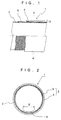
- Fig. 1 shows the general layout of a flexible tube which constitutes an endoscopic biopsy channel
- Fig. 2 shows the flexible tube in a transverse section.
- a flexible tube 1 which constitutes a biopsy channel in an endoscopic insertion instrument is composed of an inner layer 2 and an outer layer 3.
- the inner layer 2 is formed of a thin film tube of air tight and low friction coefficient material, preferably of tetrafluoroethylene resin (PTFE) or non-calcined hexafluoroethylene resin.
- the outer layer 3 is formed of a main tube body layer 4 and a reinforcing layer 5 which consists of metal mesh or metal knit fabric.
- the mesh 5 is directly laminated on the inner layer 2, and is formed by knitting or weaving hard metal fiber having spring action, for example, like hard stainless steel fiber, amorphous metal fiber or tungsten fiber.
- the main tube body layer 4 consists of a urethane resin layer which is formed on the mesh layer 5 by extrusion molding.
- the inner layer 2 which is formed of a fluorine-base resin, serves to impart slipperiness to the inner surface of the flexible tube 1. Accordingly, the inner layer 2 is in the form of a thin film having a thickness approximately in the range of 0.03mm to 0.2mm. Considering washability, the thin film of the inner layer 2 is preferred to be non-porous and to have extremely smooth surfaces of low friction coefficient.
- the mesh layer 5 which constitutes part of the outer layer 3 is constituted by a knitting of intertwined filaments of hard stainless steel, for example, of SUS 304 WPB and of approximately 0.1mm in diameter.
- the angle section is bent through approximately 180 degrees in a radius of curvature of about 15mm.
- the bias angle of the knitting which constitutes the mesh layer 5 is preferred to be approximately in the range between 70 degrees and 50 degrees.
- the main tube body layer 4 should have a thickness which is sufficient for completely covering the mesh layer 5, and at the same time should be of a soft type, for example, 80 degrees polyurethane which will not resist or distort movements of the mesh layer 5 when stretched or contracted within the flexible tube 1 by flexure of the latter.
- the outer layer 3 which is composed of the main tube body layer 4 and the mesh layer 5 needs to be connected to the inner layer 2 as firmly as possible to prevent detachment or exfoliations which might occur in boundary regions when the flexible tube is repeatedly bent in arbitrary directions.
- an adhesive can be used for bonding the outer and inner layers 3 and 2 to each other.
- the fluorine resin inner layer 2 has extremely smooth surfaces, so that an outer layer which is formed simply by laminating urethane resin on the inner layer 2 can be incapable of forming strong bondage to the inner layer 2 and can be easily detached from the latter.
- an etching treatment is given to the outer peripheral surface of the tube before laminating the mesh layer 5 and the main tube body layer 4 successively thereon.
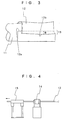
- Described below is a method for fabricating the flexible tube 1.
- an inner layer 2 in the form of a thin film tube is formed in the manner as shown in Fig. 3. More specifically, a thin film sheet 12 is formed into a tubular shape by wrapping same around a core rod 11 of metal or other suitable material. Thus, the inside diameter of the flexible tube 1 is determined by the outside diameter of the core 11.
- the thin film sheet 12 is of a fluorine resin, for example, of a non-calcined tetrafluoroethylene resin (PTFE) and has a thickness in the range of from 0.03mm to 0.2mm.
- PTFE non-calcined tetrafluoroethylene resin
- the thin film sheet 12 is wrapped around the core rod 11 not just one round but wrapped in such a way that extra margins 12a and 12b at the opposite meeting ends of the thin film sheet 12 are overlapped one on the other over a predetermined width B. Therefore, the resulting thin film tube contains a double-thick overlapped portion 13 which extends longitudinally of the tube at one side thereof and in parallel relation with the axis of the core 11.
- the thin film sheet 12 which is in a non-calcined state at this stage is hardened by firing in a later stage.
- Figs. 4 and 5 Shown in Figs. 4 and 5 are a stage for forming the thin film sheet 12 into a cylindrical shape and a succeeding firing stage.
- indicated at 14 is a drawing die and at 15 a firing furnace.
- the core rod 11 is in the form of a lengthy round rod
- the thin film sheet 12 is in the form of an elongated strip having a width which corresponds to the circumferential length of the core rod 11 plus the widths of the overlapping margins 12a and 12b.
- the core rod 11 is fed in a forward direction as indicated by an arrow in Fig. 5, the thin film sheet 12 is wrapped around the circumference of the core rod 11 within the drawing die 14.
- the rolled thin film 12 on the core rod 11 is calcined in the firing furnace 15 approximately at 400°C for 10 to 60 seconds.
- the overlapped portions intimately adhered to each other, and at the same time the rolled thin film sheet 12 as a whole is thermally hardened by calcination to form the tubular inner layer 2.
- the inner layer 2 of PTFE comes to have flexibility in bending directions because it is extremely thin.
- the thin film sheet 12 of the inner layer 2 is non-porous and, because of the overlapped portion, the inner layer 2 can guarantee extremely air- and water-tightness.
- the overlapped portion forms a thick wall portion 6 of a predetermined width which extends longitudinally of the tubular inner layer 2. After firing and hardening, the thick wall portion 6 is approximately doubled in thickness, more specifically, is 1.7 times as thick as remainder portions of the inner layer 2.
- a chemical etching treatment the inner layer 2 is immersed in an etching solution dissolving a complex of sodium and ammonia or an etching solution dissolving a complex of sodium and naphthalene in tetrahydrafuran. In the time of this chemical etching, the inner layer 2 is still fitted on the core 11.
- outer surfaces of the inner layer are roughened to increase the strength of bond to other synthetic resin material of the fluorine resin which normally has extremely weak bonding strength to other synthetic resin material.
- an etching treatment solves this problem and can preclude possibilities of detachment or exfoliation of a thermoplastic resin layer which is laminated on the inner layer 2.
- the time duration of immersion in the etching solution is suitably in the range of from 1 to 60 seconds.
- the etching treatment for roughening the outer surfaces of the inner layer 2 is not limited to chemical etching treatments but can be a mechanical abrasive etching treatment.
- a mesh layer 5 of knit metal fiber is formed as a reinforcing layer on and around the etched outer surfaces of the inner layer 2, which is still on the core 11. More specifically, in this particular embodiment, the mesh layer 5 is knit on and around the inner layer 2 by the use a netting frame 16 and a positioning ring 17 as shown in Fig. 6. While the inner layer 2 is being fed in the direction indicated by an arrow, a number of groups of metal filaments are intertwined with each other in shifted positions. Direct knitting of the mesh layer 5 on the inner layer 2 is preferable from the stand point of shape retainability. After forming the mesh layer 5 on and around the inner layer 2, the main tube body layer 4 is laminated on in such a way as to completely cover the mesh layer 5.
- the outer layer 3 which is composed of the mesh layer 5 and the main tube body layer 4 is formed integrally around the inner layer 2.
- the main tube body layer 4 can be laminated on the mesh layer 2 which is directly knit on the inner layer 2, for example, by the use of an extruder or extrusion molding machine 18 as shown in Fig. 7.
- feed rollers 19 and 19' are provided on the upstream and downstream sides of the extruder 18 to feed the assembled tube in the direction indicated by an arrow in Fig. 7.
- the flexible tube 1 of the ultimate product is thus formed on the core rod 11. After extraction of the core rod 11, the flexible tube 11 is cut into a unit length, for example, into a length suitable for use as a biopsy channel of an endoscope.
- the inner PTFE layer 2 of the flexible tube 11 has excellent properties in slipperiness, low friction coefficient, resistance to chemicals, disinfection by washing, biotic safety etc.
- the inner layer 2 formed of a non-porous thin film having longitudinal side portions intimately overlapped and closed one on the other, also has excellent properties in air- and water-tightness.
- all of the component parts of the flexible tube 1, i.e., the inner layer 2, mesh layer 5 and main tube body layer 4 have sufficient flexibility at least in bending directions.
- the existence of the thick wall portion 6 in the inner layer 2 does not give rise to any problem in this regard because it is formed of an extremely thin film and as thin as 0.3mm to 0.2mm even in that portion.
- the outer surface of the inner layer 2, roughened by an etching treatment is capable of forming a sufficiently strong bond to the outer layer 3 for preventing exfoliation of tube layers.
- the flexible tube construction having the inner layer 2 of an extremely thin film, the mesh layer 5 directly knit on and around the inner layer 2 and the main tube body layer 4 laminated around the mesh layer 5, can contribute to reduce the thickness of the flexible tube 1 as a whole to a considerable degree.
- the flexible tube 1 can be widely applied to medical endoscopes or to serve other purposes in medial fields. However, it can be most suitably applied as an endoscopic biopsy channel.
- Fig. 8 shows a general layout of an endoscope
- Fig. 9 shows in section a fore end portion of an endoscopic insertion instrument.
- an endoscope itself, including a manipulating head assembly 21, an insertion instrument 22 which is extended out on the front side of the manipulating head assembly 21 for introduction into a body cavity of a patient, and a universal cable 23 for disconnectibly connecting the endoscope to a light source and so forth.
- the insertion instrument 22 is constituted by an elongated flexible body 22a, an angle section 22b and a rigid tip end section 22c successively from the side of the manipulating head assembly 21.
- the rigid tip end section 22c is formed with an illumination window or windows for illuminating an intracavitary portion under observation, along with an observation window which is fitted with an image pickup means including an optical objective lens system and a solid-state image sensor device.
- the angle section 22b is provided for the purpose of turning the observation window on rigid tip end section 22c into arbitrary directions, and, as shown in Fig.
- the angle section 22b can be angularly turned in upward, downward, rightward and leftward directions.
- a pair of upper and lower operating wires and a pair of right and left operating wires 27 are passed internally of the angle section 22b.
- One of the paired upper and lower operating wires 27 is pulled or loosened at the time of bending the angle section 22b in an upward or downward direction.
- one of the paired right and left operating wires 27 is pulled or loosened at the time of bending the angle section 22b in a rightward or leftward direction.
- a biopsy channel which is provided coextensively in the endoscopic insertion instrument.
- the biopsy channel 30 is constituted by a through hole 31 which is provided on the rigid tip end section 22a, a connector pipe 32 which is partly fitted in the through hole 31, and a flexible tube 33 having a fore end portion thereof fitted on a proximal end portion of the connector pipe 32.
- the flexible tube 33 is constituted by a flexible tube which is same as the flexible tube 1 in construction and fabricated in the same manner as described hereinbefore.
- the fore open end of the above-mentioned through hole 31 on the rigid tip end section 22a provides an exit opening of the biopsy channel.
- the flexible tube 33 of the biopsy channel 30 is composed of an inner layer 34 and an outer layer 35 in the same manner as the above-described flexible tube 1.
- the inner layer 34 contains a thick wall portion 36 of a predetermined width B which extends longitudinally at one angular position around the circumference of the tubular inner layer 34.
- the angle section 22b can be flexibly bent in upward, downward, leftward and rightward directions as indicated by arrows U, D, L and R, respectively.
- the flexible tube 33 of the biopsy channel is fitted in the endoscopic insertion instrument such that the thick wall portion 36 of the inner layer 34 is positioned on the lower side, that is, on the side of the lower operating wire 27. Accordingly, when the angle section 22b is bent upward, the thick wall portion 36 of the inner layer 34 comes to lie along the outer side of an arcuate bend as shown particularly in Fig. 11.
- the thick wall portion 36 in the inner layer 34 of the flexible tube 33 of the biopsy channel 30 is located on the outer side of the bend as described above.
- the thick wall portion 36 in the inner layer 34 is extended parallel with the longitudinal axis of the flexible tube 33, it contains no stepped surface portions or such surface irregularities as would obstruct passage of forceps F or other inserted instruments.
- the inner layer 34 of the flexible tube 33 is constituted by a thin film of an almost infinitesimal thickness. Therefore, it becomes possible to reduce the diameter of the biopsy channel 30 or the diameter of the endoscopic insertion instrument 22. In other words, for the purpose of facilitating insertion of forceps F or other instruments, the inside diameter of the biopsy channel 30 can be increased without changing its outside diameter. Besides, the reduction in thickness of the inner layer 34 contributes to impart higher flexibility to the biopsy channel 30 as a whole particularly in bending directions.
- the inner layer 34 of the biopsy channel 30 is extraordinarily small in thickness but has favorable slipperiness and low friction coefficient. Accordingly, unless the biopsy channel 30 is bent to an exceptionally acute angle as shown in Fig. 11, inserted forceps F or other biopsy or surgical instruments are allowed to advance smoothly within the biopsy channel 30 substantially free of resistive forces. In this respect, as long as inner surfaces of the biopsy channel 30 have sufficient properties in slipperiness and friction coefficient, normally it is immune from abrasive wear, frictional damages and so forth even if the inner layer 34 is in the form of a thin film of an infinitesimal thickness. However, in case the endoscopic insertion instrument is frequently used in an acutely bent form as shown in Fig. 11, inner surfaces of the biopsy channel 30 become more susceptible to abrasive wear and frictional damages.
- the angle section 22b of the endoscopic insertion instrument When angularly bending the angle section 22b of the endoscopic insertion instrument within a body cavity to turn the rigid tip end section 22c into arbitrary directions, looking for a particular intracavitary site within a view field of the observation window on the rigid tip end section for a therapeutic treatment or for sampling tissues, it is usually the case that an operator tends to bend the angle section 22b in an upward direction most frequently and to a maximum degree. Accordingly, the location of the thick wall portion 36 on the outer side of an arcuate bend in the angle section 22b, which is turned in an upward direction, has great significance in the sense of reinforcement because the strength and durability of the biopsy channel 30 can be improved markedly.
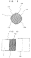
- the angle section which is flexibly bendable in upward, downward, rightward and leftward directions, it can be bent in any one of these directions when the forceps F is introduced into the biopsy channel 30. Therefore, the thick wall portion in the inner layer 34 can be provided in each one of these four directions (in a plural number of directions in which the angle section 22b is bent more frequently).
- a tubular inner layer 102 with four thick wall portions can be formed by overlapping lateral side portions of four thin film sheets 112 when forming same into a tube on a core rod 11.
- the flexible tube according to the present invention can be applied as an air/water feed tube, an endoscopic guide tubes, a catheter, an outfit tube of a control cable for axially displacing an objective lens system of an endoscopic image pickup, or as a flexible stem portion of a biopsy or surgical instrument.
- the main tube body layer 4 is formed and laminated on and around the mesh layer 4 by extrusion molding.
- the main tube body layer 4 can also be formed in the manner as described below.
- a tube of a thermoplastic synthetic resin material for example, an urethane resin tube 104 as shown in Fig. 13.
- the urethane resin tube 104 Prior to fitting the urethane resin tube 104 on the mesh layer 5, the latter is knit around the inner layer 2 on a core rod 11 in the same manner as in the foregoing first embodiment. Then, the urethane resin tube 104 is fitted on the mesh layer 5.
- the urethane resin tube 104 can be fitted on quite easily because its inside diameter is larger than the outside diameter of the mesh layer 5. Further, a heat-shrinkable tubing 105 is fitted on the urethane tube 104 which is fitted on the mesh layer 5 in the manner as described above.
- the tube assembly on the core rod 11 composed of four layers including the inner layer 2, mesh layer 5, urethane tube 104 and heat-shrinkable tube 105, is heated to integrate the respective layers.
- the heating temperature should lower than the firing temperature of the inner layer 2 but higher than a temperature at which the urethane tube 104 begins to soften.
- the urethane tube 104 which is interposed between the mesh layer 5 and the heat-shrinkable tube 105 heated to a softened or molten state.
- the heat-shrinkable tube 105 on the outer side of the urethane tube 104 is shrunk into a smaller diameter, pressing the softened or molten urethane tube 104 into the mesh layer 5 to integrate these layers with each other.
- the heat-shrinkable tube 105 is removed by the use of a cutter or scissors to obtain the flexible tube 1 having the mesh layer 5 integrally and inseparably embedded in the main tube body layer 4 of the urethane tube 104.
- the flexible tube 1 is enhanced in strength and free of the problem of exfoliation or detachment of the main tube body layer 4 from the mesh layer 5 even if it is repeatedly bent to an acute angle or twisted from time to time.
Landscapes
- Engineering & Computer Science (AREA)
- Health & Medical Sciences (AREA)
- Life Sciences & Earth Sciences (AREA)
- Mechanical Engineering (AREA)
- General Engineering & Computer Science (AREA)
- Surgery (AREA)
- Radiology & Medical Imaging (AREA)
- Heart & Thoracic Surgery (AREA)
- Optics & Photonics (AREA)
- Pathology (AREA)
- Biophysics (AREA)
- Physics & Mathematics (AREA)
- Biomedical Technology (AREA)
- Nuclear Medicine, Radiotherapy & Molecular Imaging (AREA)
- Medical Informatics (AREA)
- Molecular Biology (AREA)
- Animal Behavior & Ethology (AREA)
- General Health & Medical Sciences (AREA)
- Public Health (AREA)
- Veterinary Medicine (AREA)
- Endoscopes (AREA)
- Rigid Pipes And Flexible Pipes (AREA)
Claims (8)
- Flexibler Schlauch (1), der aufweist:eine äußere Schicht (3), die eine Hauptschlauchkörperschicht (4) aus einem thermoplastischen Kunststoff vorgegebener Dicke und eine Verstärkungsschicht (5), die auf der Innenseite der Hauptschlauchkörperschicht in fester Verbindung damit vorgesehen ist, aufweist, undeine innere Schicht (2) aus einem dünnen Film aus einem luftdichten und reibungsarmen Material, die auf der Innenseite der Verstärkungsschicht vorgesehen ist;wobei die innere Schicht hergestellt ist durch Rollen eines dünnen Films (12) zu einer Schlauchform in der Weise, dass gegenüberliegende Seiten (12a, 12b) des dünnen Films einander zu einem bestimmten Grad überlappen, so dass ein dicker Wandbereich (6) einer vorgegebenen Breite gebildet wird, der sich längs der inneren Schicht und in einer Winkelposition der inneren Schicht erstreckt.
- Flexibler Schlauch nach Anspruch 1, bei dem die innere Schicht aus einem dünnen Film von im Wesentlichen einheitlicher Dicke besteht, der durch einen Umlauf auf sich selbst gerollt wird, bis eine seitliche Seite des dünnen Films bis zu einem bestimmten Maß mit der anderen seitlichen Seite überlappt, um einen dicken Wandbereich mit einer vorgegebenen Breite zu bilden, der sich längs der inneren Schicht und in einer Winkelposition der inneren Schicht erstreckt.
- Flexibler Schlauch nach Anspruch 1, bei dem die innere Schicht aus einem dünnen Film mit im Wesentlichen einheitlicher Dicke, der mehrmals auf sich selbst ausgerollt ist, gebildet wird.
- Flexibler Schlauch nach Anspruch 1, der in ein Einschubinstrument (22) eines Endoskopes (20) eingepasst ist, um als ein Biopsiekanal (30) für das Einführen von Biopsie- oder Operations-Therapieinstrumente zu dienen und bei dem der dicke Wandbereich in einer Winkelposition des Biopsiekanals liegt, in der das Biopsie- oder Operations-Instrument meistens gegen eine innere Oberfläche des Biopsiekanals (30) rutscht, wenn ein Winkelabschnitt (22b) des endoskopischen Instrumentes flexibel in eine Winkelform gebogen ist.
- Flexibler Schlauch nach Anspruch 4, bei dem der Winkelabschnitt in mindestens zwei vorgegebenen Richtungen flexibel biegbar ist und bei dem die innere Schicht aus mehreren dünnen Filmen besteht, um längs verlaufende dicke Wandbereiche mit vorgegebenen Breite an zwei verschiedenen Winkelpositionen der Innenschicht vorzusehen, so dass jeder dicke Wandbereich auf der Außenseite einer Biegung lokalisiert ist, wenn der Winkelabschnitt des endoskopischen Einführungsinstrumentes in jede der beiden Richtungen gebogen ist.
- Flexibler Schlauch nach Anspruch 4, bei dem die innere Schicht aus einem dünnen Film entweder aus nicht-kalziniertem Tetrafluoroethylenharz oder aus nicht-kalziniertem Hexafluoroethylenharz besteht.
- Flexibler Schlauch nach Anspruch 1 oder 4, bei dem die Hauptschlauchkörperschicht aus mindestens einem Bauteil, das aus einer Gruppe aus Urethanharz, Nylon und Polyethylen ausgewählt wird, besteht, und bei dem die Verstärkungsschicht aus einem Metallgeflecht in der Form einer gewirkten Struktur aus metallischen Fasern besteht.
- Verfahren zum Bau eines flexiblen Schlauchs (1), der eine laminierte Vielschichtstruktur aufweist mit einer äußeren Schicht (3), die eine Hauptschlauchkörperschicht (4) aus einem thermoplastischen Kunststoff in einer bestimmten Dicke aufweist, und mit einer Verstärkungsschicht (5), die in fester Verbindung auf der Innenseite der Hauptschlauchkörperschicht vorgesehen ist, und mit einer inneren Schicht (2) aus einem dünnen Film aus luftdichtem und reibungsarmen Material, die auf der Innenseite der Verstärkungsschicht (5) vorgesehen ist,
wobei das Verfahren folgende Schritte aufweist:Bilden der inneren Schicht (2), indem ein länglicher Streifen eines Blattes aus dünnem Film (12) um einen Kernstab gewickelt wird, und zwar so, dass gegenüberliegende seitliche Seiten des Blattes aus dünnem Film (12) einander zu einem vorgegebenen Grad überlappen, um einen dicken Wandbereich (6) einer bestimmten Breite, der sich längs der inneren Schicht und in einer Winkelposition der inneren Schicht erstreckt, vorzusehen,Ätzen der äußeren Oberflächen der inneren Schicht (2) auf dem Kernstab (11);Bilden einer Verstärkungsnetzschicht (5) auf der inneren und um die innere Schicht (2), indem Metallfäden direkt auf den und um die geätzten äußeren Oberflächen der inneren Schicht (2) gewirkt werden; undBilden der Hauptschlauchkörperschicht (4) indem thermoplastischer Kunststoff auf und um die Verstärkungsnetzschicht geschichtet wird.
Applications Claiming Priority (2)
| Application Number | Priority Date | Filing Date | Title |
|---|---|---|---|
| JP2000278310 | 2000-09-13 | ||
| JP2000278310A JP3835146B2 (ja) | 2000-09-13 | 2000-09-13 | 可撓性チューブ及びその製造方法 |
Publications (3)
| Publication Number | Publication Date |
|---|---|
| EP1188976A2 EP1188976A2 (de) | 2002-03-20 |
| EP1188976A3 EP1188976A3 (de) | 2002-06-19 |
| EP1188976B1 true EP1188976B1 (de) | 2006-01-04 |
Family
ID=18763493
Family Applications (1)
| Application Number | Title | Priority Date | Filing Date |
|---|---|---|---|
| EP01121662A Expired - Lifetime EP1188976B1 (de) | 2000-09-13 | 2001-09-13 | Schlauch und Verfahren zu seiner Herstellung |
Country Status (4)
| Country | Link |
|---|---|
| US (1) | US6565507B2 (de) |
| EP (1) | EP1188976B1 (de) |
| JP (1) | JP3835146B2 (de) |
| DE (1) | DE60116422T2 (de) |
Families Citing this family (59)
| Publication number | Priority date | Publication date | Assignee | Title |
|---|---|---|---|---|
| US20040267349A1 (en) | 2003-06-27 | 2004-12-30 | Kobi Richter | Amorphous metal alloy medical devices |
| US8382821B2 (en) | 1998-12-03 | 2013-02-26 | Medinol Ltd. | Helical hybrid stent |
| JP4418096B2 (ja) * | 2000-09-08 | 2010-02-17 | オリンパス株式会社 | 内視鏡 |
| LU90796B1 (en) * | 2001-06-27 | 2002-12-30 | Delphi Tech Inc | Process for injection moulding a connection pipe |
| US6921363B2 (en) * | 2002-10-03 | 2005-07-26 | Koninklijke Philips Electronics N.V. | Transesophageal endoscope with improved bite-through protection |
| JP3965108B2 (ja) * | 2002-11-29 | 2007-08-29 | オリンパス株式会社 | 内視鏡の可撓管 |
| JP4013194B2 (ja) * | 2002-12-02 | 2007-11-28 | 株式会社町田製作所 | 内視鏡等の可撓管およびその製造方法 |
| US20040225186A1 (en) * | 2003-01-29 | 2004-11-11 | Horne Guy E. | Composite flexible endoscope insertion shaft with tubular substructure |
| US20050245789A1 (en) | 2003-04-01 | 2005-11-03 | Boston Scientific Scimed, Inc. | Fluid manifold for endoscope system |
| US8118732B2 (en) | 2003-04-01 | 2012-02-21 | Boston Scientific Scimed, Inc. | Force feedback control system for video endoscope |
| US20040199052A1 (en) | 2003-04-01 | 2004-10-07 | Scimed Life Systems, Inc. | Endoscopic imaging system |
| US7578786B2 (en) | 2003-04-01 | 2009-08-25 | Boston Scientific Scimed, Inc. | Video endoscope |
| US7591783B2 (en) | 2003-04-01 | 2009-09-22 | Boston Scientific Scimed, Inc. | Articulation joint for video endoscope |
| US9039755B2 (en) | 2003-06-27 | 2015-05-26 | Medinol Ltd. | Helical hybrid stent |
| US9155639B2 (en) | 2009-04-22 | 2015-10-13 | Medinol Ltd. | Helical hybrid stent |
| US20050288545A1 (en) * | 2004-03-31 | 2005-12-29 | Jun Matsumoto | Flexible tube for endoscope and method for manufacturing the same |
| JP3821392B2 (ja) * | 2004-06-14 | 2006-09-13 | 有限会社エスアールジェイ | 内視鏡装置 |
| US8357148B2 (en) | 2004-09-30 | 2013-01-22 | Boston Scientific Scimed, Inc. | Multi-functional endoscopic system for use in electrosurgical applications |
| EP1799096A2 (de) | 2004-09-30 | 2007-06-27 | Boston Scientific Scimed, Inc. | System und verfahren zur entfernung von verstopfungen |
| US7241263B2 (en) | 2004-09-30 | 2007-07-10 | Scimed Life Systems, Inc. | Selectively rotatable shaft coupler |
| US7479106B2 (en) | 2004-09-30 | 2009-01-20 | Boston Scientific Scimed, Inc. | Automated control of irrigation and aspiration in a single-use endoscope |
| WO2006039522A2 (en) | 2004-09-30 | 2006-04-13 | Boston Scientific Scimed, Inc. | Adapter for use with digital imaging medical device |
| US8083671B2 (en) | 2004-09-30 | 2011-12-27 | Boston Scientific Scimed, Inc. | Fluid delivery system for use with an endoscope |
| US8097003B2 (en) | 2005-05-13 | 2012-01-17 | Boston Scientific Scimed, Inc. | Endoscopic apparatus with integrated variceal ligation device |
| US7846107B2 (en) | 2005-05-13 | 2010-12-07 | Boston Scientific Scimed, Inc. | Endoscopic apparatus with integrated multiple biopsy device |
| JP2007050104A (ja) * | 2005-08-18 | 2007-03-01 | Pentax Corp | 内視鏡用可撓管 |
| US8052597B2 (en) | 2005-08-30 | 2011-11-08 | Boston Scientific Scimed, Inc. | Method for forming an endoscope articulation joint |
| US7967759B2 (en) | 2006-01-19 | 2011-06-28 | Boston Scientific Scimed, Inc. | Endoscopic system with integrated patient respiratory status indicator |
| US8888684B2 (en) | 2006-03-27 | 2014-11-18 | Boston Scientific Scimed, Inc. | Medical devices with local drug delivery capabilities |
| US7955255B2 (en) | 2006-04-20 | 2011-06-07 | Boston Scientific Scimed, Inc. | Imaging assembly with transparent distal cap |
| US8202265B2 (en) | 2006-04-20 | 2012-06-19 | Boston Scientific Scimed, Inc. | Multiple lumen assembly for use in endoscopes or other medical devices |
| CA2652249A1 (en) * | 2006-05-17 | 2007-11-29 | Kent Moore | Stereovideoscope and method of using the same |
| EP2032201B1 (de) * | 2006-06-01 | 2013-04-03 | Cathprint AB | Rohrförmiger katheter für invasive verwendung und herstellungsverfahren dafür |
| FR2903342B1 (fr) * | 2006-07-10 | 2010-01-15 | Daher Lhotellier Aerotechnolog | Dispositif thermodurcissable ou thermoplastique pour la fabrication de tuyauterie de conditionnement d'air |
| US20090065565A1 (en) * | 2007-09-12 | 2009-03-12 | Vascular Technologies, Inc. | System, method and apparatus for preventing reuse of medical instruments |
| US8673100B2 (en) * | 2007-10-19 | 2014-03-18 | Stephen A. Leeflang | Strip lined catheters and methods for constructing and processing strip lined catheters |
| US8888683B2 (en) * | 2008-01-28 | 2014-11-18 | Mauricio Mejia | Modifications in endoscope apparatus, using fluid and gas dynamics, and methods for improving visibility during endoscopy |
| US20090192355A1 (en) * | 2008-01-28 | 2009-07-30 | Mauricio Mejia | Scope for managing difficult pathways and method to improve visibility of the same |
| US20090192350A1 (en) * | 2008-01-28 | 2009-07-30 | Mauricio Mejia | Wireless video stylet with display mounted to laryngoscope blade and method for using the same |
| US20090247826A1 (en) * | 2008-03-28 | 2009-10-01 | Olympus Corporation | Tube for endoscope |
| JP2009254798A (ja) * | 2008-03-28 | 2009-11-05 | Olympus Medical Systems Corp | 内視鏡用配管 |
| WO2013074036A1 (en) * | 2011-11-16 | 2013-05-23 | Cathprint Ab | Catheter component |
| US8419720B1 (en) | 2012-02-07 | 2013-04-16 | National Advanced Endoscopy Devices, Incorporated | Flexible laparoscopic device |
| FR2987880B1 (fr) * | 2012-03-09 | 2014-05-02 | Saint Gobain Pont A Mousson | Element tubulaire et procede correspondant |
| DE102012011636A1 (de) * | 2012-06-12 | 2013-12-12 | Automatik Plastics Machinery Gmbh | Einzugswalze für Stranggranulatoren |
| US9629978B2 (en) * | 2013-05-20 | 2017-04-25 | Clph, Llc | Catheters with intermediate layers and methods for making them |
| US9840266B2 (en) | 2013-10-09 | 2017-12-12 | Glidemachines Llc | Apparatus and method for towing a load by a person |
| JPWO2016052208A1 (ja) * | 2014-10-03 | 2017-04-27 | オリンパス株式会社 | 挿入機器の挿入部及び挿入機器 |
| US10588491B2 (en) * | 2014-12-19 | 2020-03-17 | University Hospitals Health System, Inc. | Accessory medical device introduction apparatus for endoscopes |
| WO2017209754A1 (en) * | 2016-06-02 | 2017-12-07 | GYRUS ACMI, INC. (d/b/a OLYMPUS SURGICAL TECHNOLOGIES AMERICA) | Endoscope working channel protection |
| JP7048628B2 (ja) | 2016-11-28 | 2022-04-05 | アダプティブエンドウ エルエルシー | 分離可能使い捨てシャフト付き内視鏡 |
| JP2018121952A (ja) * | 2017-02-02 | 2018-08-09 | 住友電気工業株式会社 | 多層チューブ |
| WO2018191063A1 (en) * | 2017-04-14 | 2018-10-18 | Inventio, Inc. | Endoscope shaft |
| USD1018844S1 (en) | 2020-01-09 | 2024-03-19 | Adaptivendo Llc | Endoscope handle |
| JP7390651B2 (ja) * | 2020-01-31 | 2023-12-04 | 日立Geニュークリア・エナジー株式会社 | 伸縮装置 |
| US11498654B2 (en) * | 2020-05-18 | 2022-11-15 | The Boeing Company | Automated system and method for preparing a mandrel for use in composite stringer manufacturing |
| US20230296194A1 (en) * | 2020-10-05 | 2023-09-21 | Junkosha Inc. | Tube |
| USD1031035S1 (en) | 2021-04-29 | 2024-06-11 | Adaptivendo Llc | Endoscope handle |
| CN113324108B (zh) * | 2021-06-23 | 2022-06-03 | 南昌务求环保科技有限公司 | 一种用于通风除尘的圆形布料伸缩管及其制作方法 |
Family Cites Families (14)
| Publication number | Priority date | Publication date | Assignee | Title |
|---|---|---|---|---|
| US3915618A (en) * | 1972-02-10 | 1975-10-28 | Goodyear Tire & Rubber | Apparatus for making hose |
| US3799152A (en) * | 1972-08-21 | 1974-03-26 | S Kim | Flexible and expandable esophagoscope |
| JPS644335Y2 (de) * | 1984-10-09 | 1989-02-03 | ||
| JPH0447402U (de) * | 1990-08-24 | 1992-04-22 | ||
| US5176659A (en) * | 1991-02-28 | 1993-01-05 | Mario Mancini | Expandable intravenous catheter and method of using |
| JPH0745219B2 (ja) * | 1991-05-20 | 1995-05-17 | 富士写真光機株式会社 | 可撓性チューブ及びその製造方法 |
| JP3123565B2 (ja) * | 1991-10-04 | 2001-01-15 | 株式会社潤工社 | 医療用チューブ及びその製造方法 |
| JP3184387B2 (ja) * | 1992-12-25 | 2001-07-09 | ジャパンゴアテックス株式会社 | 可とう性多層チューブ |
| US5674182A (en) * | 1993-02-26 | 1997-10-07 | Olympus Optical Co., Ltd. | Endoscope system including endoscope and protection cover |
| JP2822843B2 (ja) * | 1993-05-20 | 1998-11-11 | 富士写真光機株式会社 | 内視鏡の被覆チューブの製造方法 |
| US6027779A (en) * | 1993-08-18 | 2000-02-22 | W. L. Gore & Associates, Inc. | Thin-wall polytetrafluoroethylene tube |
| JPH09501583A (ja) * | 1993-08-18 | 1997-02-18 | ダブリュ.エル.ゴア アンド アソシエイツ,インコーポレイティド | チューブ状の管腔内移植片 |
| US5789047A (en) * | 1993-12-21 | 1998-08-04 | Japan Gore-Tex, Inc | Flexible, multilayered tube |
| JPH1128186A (ja) * | 1997-07-10 | 1999-02-02 | Olympus Optical Co Ltd | 内視鏡 |
-
2000
- 2000-09-13 JP JP2000278310A patent/JP3835146B2/ja not_active Expired - Fee Related
-
2001
- 2001-09-13 DE DE60116422T patent/DE60116422T2/de not_active Expired - Lifetime
- 2001-09-13 US US09/950,653 patent/US6565507B2/en not_active Expired - Fee Related
- 2001-09-13 EP EP01121662A patent/EP1188976B1/de not_active Expired - Lifetime
Also Published As
| Publication number | Publication date |
|---|---|
| DE60116422D1 (de) | 2006-03-30 |
| EP1188976A2 (de) | 2002-03-20 |
| DE60116422T2 (de) | 2006-08-10 |
| US20020032370A1 (en) | 2002-03-14 |
| US6565507B2 (en) | 2003-05-20 |
| JP3835146B2 (ja) | 2006-10-18 |
| JP2002085334A (ja) | 2002-03-26 |
| EP1188976A3 (de) | 2002-06-19 |
Similar Documents
| Publication | Publication Date | Title |
|---|---|---|
| EP1188976B1 (de) | Schlauch und Verfahren zu seiner Herstellung | |
| JP3927764B2 (ja) | 内視鏡用可撓管 | |
| US6315715B1 (en) | Flexible inner liner for the working channel of an endoscope | |
| US6464632B1 (en) | Flexible inner liner for the working channel of an endoscope | |
| US6554820B1 (en) | Composite flexible tube for medical applications | |
| US5279280A (en) | Endoscope with grooved outer surface | |
| US4753222A (en) | Endoscopic flexible tube | |
| US7534317B2 (en) | Kink-resistant access sheath and method of making same | |
| US20060064054A1 (en) | Longitudinal sheath enforcement | |
| US8568297B2 (en) | Propellable apparatus and related methods | |
| US20150088151A1 (en) | Elongated member for medical use and connecting member | |
| JP6621963B2 (ja) | 内視鏡用可撓管の製造方法および内視鏡の製造方法 | |
| JPH06154335A (ja) | 剛性傾斜トルクチューブ、その製造方法およびそのトルクチューブを用いてなるカテーテル | |
| JP2007190089A (ja) | 内視鏡用可撓管および内視鏡 | |
| JP2001321324A (ja) | 内視鏡用可撓管 | |
| US8568298B2 (en) | Propellable apparatus and related methods | |
| JP4801434B2 (ja) | 内視鏡用可撓管 | |
| JPH11197249A (ja) | カテーテルチューブの製造方法 | |
| EP1231972A1 (de) | Verstärkter katheter mit elliptischem draht | |
| JP2001238851A (ja) | 内視鏡の可撓管 | |
| WO1994015522A9 (en) | Endoscope with grooved outer surface | |
| JPH06217937A (ja) | 内視鏡 | |
| JP2010035759A (ja) | 内視鏡 | |
| JP2004290322A (ja) | 内視鏡の可撓管 | |
| JP2002102151A (ja) | 内視鏡用可撓管の製造方法および内視鏡用可撓管 |
Legal Events
| Date | Code | Title | Description |
|---|---|---|---|
| PUAI | Public reference made under article 153(3) epc to a published international application that has entered the european phase |
Free format text: ORIGINAL CODE: 0009012 |
|
| AK | Designated contracting states |
Kind code of ref document: A2 Designated state(s): AT BE CH CY DE DK ES FI FR GB GR IE IT LI LU MC NL PT SE TR |
|
| AX | Request for extension of the european patent |
Free format text: AL;LT;LV;MK;RO;SI |
|
| PUAL | Search report despatched |
Free format text: ORIGINAL CODE: 0009013 |
|
| AK | Designated contracting states |
Kind code of ref document: A3 Designated state(s): AT BE CH CY DE DK ES FI FR GB GR IE IT LI LU MC NL PT SE TR |
|
| AX | Request for extension of the european patent |
Free format text: AL;LT;LV;MK;RO;SI |
|
| RIC1 | Information provided on ipc code assigned before grant |
Free format text: 7A 61B 1/018 A, 7F 16L 11/10 B, 7B 29D 23/00 B, 7B 29L 23:00 Z, 7B 29L 9:00 Z |
|
| 17P | Request for examination filed |
Effective date: 20021018 |
|
| AKX | Designation fees paid |
Designated state(s): DE FR GB |
|
| 17Q | First examination report despatched |
Effective date: 20041117 |
|
| GRAP | Despatch of communication of intention to grant a patent |
Free format text: ORIGINAL CODE: EPIDOSNIGR1 |
|
| RIN1 | Information on inventor provided before grant (corrected) |
Inventor name: KIMURA, MASANORI Inventor name: KAMATA, KOUICHI Inventor name: MURAKI, KOUICHIAOBA DORMITORY 301, Inventor name: AKIBA, HARUO |
|
| RAP1 | Party data changed (applicant data changed or rights of an application transferred) |
Owner name: FUJINON CORPORATION |
|
| GRAS | Grant fee paid |
Free format text: ORIGINAL CODE: EPIDOSNIGR3 |
|
| GRAA | (expected) grant |
Free format text: ORIGINAL CODE: 0009210 |
|
| AK | Designated contracting states |
Kind code of ref document: B1 Designated state(s): DE FR GB |
|
| REG | Reference to a national code |
Ref country code: GB Ref legal event code: FG4D |
|
| REF | Corresponds to: |
Ref document number: 60116422 Country of ref document: DE Date of ref document: 20060330 Kind code of ref document: P |
|
| ET | Fr: translation filed | ||
| PLBE | No opposition filed within time limit |
Free format text: ORIGINAL CODE: 0009261 |
|
| STAA | Information on the status of an ep patent application or granted ep patent |
Free format text: STATUS: NO OPPOSITION FILED WITHIN TIME LIMIT |
|
| 26N | No opposition filed |
Effective date: 20061005 |
|
| PGFP | Annual fee paid to national office [announced via postgrant information from national office to epo] |
Ref country code: GB Payment date: 20120912 Year of fee payment: 12 |
|
| PGFP | Annual fee paid to national office [announced via postgrant information from national office to epo] |
Ref country code: DE Payment date: 20120905 Year of fee payment: 12 Ref country code: FR Payment date: 20120926 Year of fee payment: 12 |
|
| GBPC | Gb: european patent ceased through non-payment of renewal fee |
Effective date: 20130913 |
|
| REG | Reference to a national code |
Ref country code: DE Ref legal event code: R119 Ref document number: 60116422 Country of ref document: DE Effective date: 20140401 |
|
| REG | Reference to a national code |
Ref country code: FR Ref legal event code: ST Effective date: 20140530 |
|
| PG25 | Lapsed in a contracting state [announced via postgrant information from national office to epo] |
Ref country code: GB Free format text: LAPSE BECAUSE OF NON-PAYMENT OF DUE FEES Effective date: 20130913 |
|
| PG25 | Lapsed in a contracting state [announced via postgrant information from national office to epo] |
Ref country code: DE Free format text: LAPSE BECAUSE OF NON-PAYMENT OF DUE FEES Effective date: 20140401 Ref country code: FR Free format text: LAPSE BECAUSE OF NON-PAYMENT OF DUE FEES Effective date: 20130930 |