EP2032201B1 - Rohrförmiger katheter für invasive verwendung und herstellungsverfahren dafür - Google Patents
Rohrförmiger katheter für invasive verwendung und herstellungsverfahren dafür Download PDFInfo
- Publication number
- EP2032201B1 EP2032201B1 EP07748192A EP07748192A EP2032201B1 EP 2032201 B1 EP2032201 B1 EP 2032201B1 EP 07748192 A EP07748192 A EP 07748192A EP 07748192 A EP07748192 A EP 07748192A EP 2032201 B1 EP2032201 B1 EP 2032201B1
- Authority
- EP
- European Patent Office
- Prior art keywords
- support member
- invasive use
- use according
- invasive
- partly
- Prior art date
- Legal status (The legal status is an assumption and is not a legal conclusion. Google has not performed a legal analysis and makes no representation as to the accuracy of the status listed.)
- Not-in-force
Links
- 238000004519 manufacturing process Methods 0.000 title description 36
- 239000000853 adhesive Substances 0.000 claims description 50
- 230000001070 adhesive effect Effects 0.000 claims description 50
- 230000003014 reinforcing effect Effects 0.000 claims description 35
- 210000002216 heart Anatomy 0.000 claims description 30
- 239000000463 material Substances 0.000 claims description 28
- 238000012545 processing Methods 0.000 claims description 11
- 238000012544 monitoring process Methods 0.000 claims description 10
- 239000013307 optical fiber Substances 0.000 claims description 10
- 210000000056 organ Anatomy 0.000 claims description 7
- 229920000642 polymer Polymers 0.000 claims description 7
- 238000003466 welding Methods 0.000 claims description 7
- 230000004936 stimulating effect Effects 0.000 claims description 5
- 230000009545 invasion Effects 0.000 claims description 4
- 239000012858 resilient material Substances 0.000 claims description 4
- 239000003153 chemical reaction reagent Substances 0.000 claims description 2
- 238000012377 drug delivery Methods 0.000 claims description 2
- 238000000034 method Methods 0.000 description 29
- 239000004020 conductor Substances 0.000 description 28
- CNQCVBJFEGMYDW-UHFFFAOYSA-N lawrencium atom Chemical compound [Lr] CNQCVBJFEGMYDW-UHFFFAOYSA-N 0.000 description 25
- 238000005259 measurement Methods 0.000 description 17
- 239000003292 glue Substances 0.000 description 13
- 210000005240 left ventricle Anatomy 0.000 description 12
- 210000001519 tissue Anatomy 0.000 description 10
- 230000008901 benefit Effects 0.000 description 9
- 229920001610 polycaprolactone Polymers 0.000 description 9
- 239000012528 membrane Substances 0.000 description 8
- 238000010276 construction Methods 0.000 description 7
- 230000006870 function Effects 0.000 description 7
- 238000001816 cooling Methods 0.000 description 6
- 230000005284 excitation Effects 0.000 description 6
- 229910052751 metal Inorganic materials 0.000 description 6
- 239000002184 metal Substances 0.000 description 6
- 238000005476 soldering Methods 0.000 description 6
- 239000000126 substance Substances 0.000 description 6
- 210000001367 artery Anatomy 0.000 description 5
- 238000010438 heat treatment Methods 0.000 description 5
- 238000003780 insertion Methods 0.000 description 5
- 230000037431 insertion Effects 0.000 description 5
- 239000000523 sample Substances 0.000 description 5
- 230000035945 sensitivity Effects 0.000 description 5
- 230000000638 stimulation Effects 0.000 description 5
- 210000003462 vein Anatomy 0.000 description 5
- 208000031481 Pathologic Constriction Diseases 0.000 description 4
- 210000000709 aorta Anatomy 0.000 description 4
- 230000015572 biosynthetic process Effects 0.000 description 4
- 239000008280 blood Substances 0.000 description 4
- 210000004369 blood Anatomy 0.000 description 4
- 210000001124 body fluid Anatomy 0.000 description 4
- 239000010839 body fluid Substances 0.000 description 4
- 230000000747 cardiac effect Effects 0.000 description 4
- 230000007246 mechanism Effects 0.000 description 4
- 230000006793 arrhythmia Effects 0.000 description 3
- 206010003119 arrhythmia Diseases 0.000 description 3
- QVGXLLKOCUKJST-UHFFFAOYSA-N atomic oxygen Chemical compound [O] QVGXLLKOCUKJST-UHFFFAOYSA-N 0.000 description 3
- 238000009530 blood pressure measurement Methods 0.000 description 3
- 238000006243 chemical reaction Methods 0.000 description 3
- 230000001419 dependent effect Effects 0.000 description 3
- 238000010586 diagram Methods 0.000 description 3
- 238000005516 engineering process Methods 0.000 description 3
- PCHJSUWPFVWCPO-UHFFFAOYSA-N gold Chemical compound [Au] PCHJSUWPFVWCPO-UHFFFAOYSA-N 0.000 description 3
- 229910052737 gold Inorganic materials 0.000 description 3
- 239000010931 gold Substances 0.000 description 3
- 210000004013 groin Anatomy 0.000 description 3
- 238000002847 impedance measurement Methods 0.000 description 3
- 239000007943 implant Substances 0.000 description 3
- 238000009413 insulation Methods 0.000 description 3
- 239000001301 oxygen Substances 0.000 description 3
- 229910052760 oxygen Inorganic materials 0.000 description 3
- 229920000052 poly(p-xylylene) Polymers 0.000 description 3
- 230000036262 stenosis Effects 0.000 description 3
- 208000037804 stenosis Diseases 0.000 description 3
- 238000002604 ultrasonography Methods 0.000 description 3
- WKBPZYKAUNRMKP-UHFFFAOYSA-N 1-[2-(2,4-dichlorophenyl)pentyl]1,2,4-triazole Chemical compound C=1C=C(Cl)C=C(Cl)C=1C(CCC)CN1C=NC=N1 WKBPZYKAUNRMKP-UHFFFAOYSA-N 0.000 description 2
- RYGMFSIKBFXOCR-UHFFFAOYSA-N Copper Chemical compound [Cu] RYGMFSIKBFXOCR-UHFFFAOYSA-N 0.000 description 2
- 239000004642 Polyimide Substances 0.000 description 2
- 229910000831 Steel Inorganic materials 0.000 description 2
- 238000013459 approach Methods 0.000 description 2
- 238000005452 bending Methods 0.000 description 2
- 210000004204 blood vessel Anatomy 0.000 description 2
- 230000008859 change Effects 0.000 description 2
- 238000010924 continuous production Methods 0.000 description 2
- 229910052802 copper Inorganic materials 0.000 description 2
- 239000010949 copper Substances 0.000 description 2
- 210000004351 coronary vessel Anatomy 0.000 description 2
- 230000006378 damage Effects 0.000 description 2
- 238000003745 diagnosis Methods 0.000 description 2
- 238000011049 filling Methods 0.000 description 2
- 239000011888 foil Substances 0.000 description 2
- 239000007789 gas Substances 0.000 description 2
- 230000004217 heart function Effects 0.000 description 2
- 239000000017 hydrogel Substances 0.000 description 2
- 238000000608 laser ablation Methods 0.000 description 2
- 238000013507 mapping Methods 0.000 description 2
- 238000000691 measurement method Methods 0.000 description 2
- 210000004165 myocardium Anatomy 0.000 description 2
- 210000005036 nerve Anatomy 0.000 description 2
- 230000003287 optical effect Effects 0.000 description 2
- 239000008188 pellet Substances 0.000 description 2
- 239000004033 plastic Substances 0.000 description 2
- 229920003023 plastic Polymers 0.000 description 2
- BASFCYQUMIYNBI-UHFFFAOYSA-N platinum Chemical compound [Pt] BASFCYQUMIYNBI-UHFFFAOYSA-N 0.000 description 2
- 229920001721 polyimide Polymers 0.000 description 2
- 230000008569 process Effects 0.000 description 2
- 238000000926 separation method Methods 0.000 description 2
- 239000007787 solid Substances 0.000 description 2
- 239000010959 steel Substances 0.000 description 2
- 230000007704 transition Effects 0.000 description 2
- 229910001369 Brass Inorganic materials 0.000 description 1
- FAPWRFPIFSIZLT-UHFFFAOYSA-M Sodium chloride Chemical compound [Na+].[Cl-] FAPWRFPIFSIZLT-UHFFFAOYSA-M 0.000 description 1
- 208000002847 Surgical Wound Diseases 0.000 description 1
- ATJFFYVFTNAWJD-UHFFFAOYSA-N Tin Chemical compound [Sn] ATJFFYVFTNAWJD-UHFFFAOYSA-N 0.000 description 1
- 239000000654 additive Substances 0.000 description 1
- 230000000996 additive effect Effects 0.000 description 1
- 239000000956 alloy Substances 0.000 description 1
- 229910045601 alloy Inorganic materials 0.000 description 1
- 230000004075 alteration Effects 0.000 description 1
- 230000003321 amplification Effects 0.000 description 1
- 239000000560 biocompatible material Substances 0.000 description 1
- 239000010951 brass Substances 0.000 description 1
- 210000005242 cardiac chamber Anatomy 0.000 description 1
- 210000003679 cervix uteri Anatomy 0.000 description 1
- 239000011248 coating agent Substances 0.000 description 1
- 238000000576 coating method Methods 0.000 description 1
- 210000003477 cochlea Anatomy 0.000 description 1
- 238000004891 communication Methods 0.000 description 1
- 229920001940 conductive polymer Polymers 0.000 description 1
- 239000013078 crystal Substances 0.000 description 1
- 238000005520 cutting process Methods 0.000 description 1
- 238000013461 design Methods 0.000 description 1
- 238000010790 dilution Methods 0.000 description 1
- 239000012895 dilution Substances 0.000 description 1
- 238000005553 drilling Methods 0.000 description 1
- 239000003814 drug Substances 0.000 description 1
- 230000005670 electromagnetic radiation Effects 0.000 description 1
- 238000002001 electrophysiology Methods 0.000 description 1
- 230000007831 electrophysiology Effects 0.000 description 1
- 238000005530 etching Methods 0.000 description 1
- 238000011156 evaluation Methods 0.000 description 1
- 230000005669 field effect Effects 0.000 description 1
- 238000007519 figuring Methods 0.000 description 1
- 238000001914 filtration Methods 0.000 description 1
- 239000012530 fluid Substances 0.000 description 1
- 230000036541 health Effects 0.000 description 1
- 238000001802 infusion Methods 0.000 description 1
- 208000014674 injury Diseases 0.000 description 1
- 238000007641 inkjet printing Methods 0.000 description 1
- 239000011810 insulating material Substances 0.000 description 1
- 238000007914 intraventricular administration Methods 0.000 description 1
- 238000005304 joining Methods 0.000 description 1
- 239000004922 lacquer Substances 0.000 description 1
- 239000007788 liquid Substances 0.000 description 1
- 238000001459 lithography Methods 0.000 description 1
- 230000033001 locomotion Effects 0.000 description 1
- 230000007257 malfunction Effects 0.000 description 1
- 238000003801 milling Methods 0.000 description 1
- 239000000203 mixture Substances 0.000 description 1
- 238000012986 modification Methods 0.000 description 1
- 230000004048 modification Effects 0.000 description 1
- 210000003205 muscle Anatomy 0.000 description 1
- 238000003199 nucleic acid amplification method Methods 0.000 description 1
- 238000004806 packaging method and process Methods 0.000 description 1
- 229910052697 platinum Inorganic materials 0.000 description 1
- 229920000193 polymethacrylate Polymers 0.000 description 1
- 229920000098 polyolefin Polymers 0.000 description 1
- 229920001296 polysiloxane Polymers 0.000 description 1
- 230000002980 postoperative effect Effects 0.000 description 1
- 102000004169 proteins and genes Human genes 0.000 description 1
- 108090000623 proteins and genes Proteins 0.000 description 1
- 238000005086 pumping Methods 0.000 description 1
- 230000007261 regionalization Effects 0.000 description 1
- 238000011160 research Methods 0.000 description 1
- 210000005241 right ventricle Anatomy 0.000 description 1
- 238000007650 screen-printing Methods 0.000 description 1
- 229920002379 silicone rubber Polymers 0.000 description 1
- 239000004945 silicone rubber Substances 0.000 description 1
- 229910052709 silver Inorganic materials 0.000 description 1
- 239000004332 silver Substances 0.000 description 1
- 229910000679 solder Inorganic materials 0.000 description 1
- 238000010561 standard procedure Methods 0.000 description 1
- 238000006467 substitution reaction Methods 0.000 description 1
- 230000008733 trauma Effects 0.000 description 1
- XLYOFNOQVPJJNP-UHFFFAOYSA-N water Substances O XLYOFNOQVPJJNP-UHFFFAOYSA-N 0.000 description 1
Images


Classifications
-
- A—HUMAN NECESSITIES
- A61—MEDICAL OR VETERINARY SCIENCE; HYGIENE
- A61N—ELECTROTHERAPY; MAGNETOTHERAPY; RADIATION THERAPY; ULTRASOUND THERAPY
- A61N1/00—Electrotherapy; Circuits therefor
- A61N1/02—Details
- A61N1/04—Electrodes
- A61N1/05—Electrodes for implantation or insertion into the body, e.g. heart electrode
-
- A—HUMAN NECESSITIES
- A61—MEDICAL OR VETERINARY SCIENCE; HYGIENE
- A61B—DIAGNOSIS; SURGERY; IDENTIFICATION
- A61B5/00—Measuring for diagnostic purposes; Identification of persons
- A61B5/02—Detecting, measuring or recording for evaluating the cardiovascular system, e.g. pulse, heart rate, blood pressure or blood flow
- A61B5/02007—Evaluating blood vessel condition, e.g. elasticity, compliance
-
- A—HUMAN NECESSITIES
- A61—MEDICAL OR VETERINARY SCIENCE; HYGIENE
- A61B—DIAGNOSIS; SURGERY; IDENTIFICATION
- A61B5/00—Measuring for diagnostic purposes; Identification of persons
- A61B5/02—Detecting, measuring or recording for evaluating the cardiovascular system, e.g. pulse, heart rate, blood pressure or blood flow
- A61B5/021—Measuring pressure in heart or blood vessels
- A61B5/0215—Measuring pressure in heart or blood vessels by means inserted into the body
-
- A—HUMAN NECESSITIES
- A61—MEDICAL OR VETERINARY SCIENCE; HYGIENE
- A61B—DIAGNOSIS; SURGERY; IDENTIFICATION
- A61B5/00—Measuring for diagnostic purposes; Identification of persons
- A61B5/05—Detecting, measuring or recording for diagnosis by means of electric currents or magnetic fields; Measuring using microwaves or radio waves
- A61B5/053—Measuring electrical impedance or conductance of a portion of the body
- A61B5/0538—Measuring electrical impedance or conductance of a portion of the body invasively, e.g. using a catheter
-
- A—HUMAN NECESSITIES
- A61—MEDICAL OR VETERINARY SCIENCE; HYGIENE
- A61B—DIAGNOSIS; SURGERY; IDENTIFICATION
- A61B5/00—Measuring for diagnostic purposes; Identification of persons
- A61B5/145—Measuring characteristics of blood in vivo, e.g. gas concentration or pH-value ; Measuring characteristics of body fluids or tissues, e.g. interstitial fluid or cerebral tissue
- A61B5/14539—Measuring characteristics of blood in vivo, e.g. gas concentration or pH-value ; Measuring characteristics of body fluids or tissues, e.g. interstitial fluid or cerebral tissue for measuring pH
-
- A—HUMAN NECESSITIES
- A61—MEDICAL OR VETERINARY SCIENCE; HYGIENE
- A61B—DIAGNOSIS; SURGERY; IDENTIFICATION
- A61B5/00—Measuring for diagnostic purposes; Identification of persons
- A61B5/24—Detecting, measuring or recording bioelectric or biomagnetic signals of the body or parts thereof
- A61B5/25—Bioelectric electrodes therefor
- A61B5/279—Bioelectric electrodes therefor specially adapted for particular uses
- A61B5/28—Bioelectric electrodes therefor specially adapted for particular uses for electrocardiography [ECG]
- A61B5/283—Invasive
- A61B5/287—Holders for multiple electrodes, e.g. electrode catheters for electrophysiological study [EPS]
-
- A—HUMAN NECESSITIES
- A61—MEDICAL OR VETERINARY SCIENCE; HYGIENE
- A61B—DIAGNOSIS; SURGERY; IDENTIFICATION
- A61B5/00—Measuring for diagnostic purposes; Identification of persons
- A61B5/68—Arrangements of detecting, measuring or recording means, e.g. sensors, in relation to patient
- A61B5/6846—Arrangements of detecting, measuring or recording means, e.g. sensors, in relation to patient specially adapted to be brought in contact with an internal body part, i.e. invasive
- A61B5/6847—Arrangements of detecting, measuring or recording means, e.g. sensors, in relation to patient specially adapted to be brought in contact with an internal body part, i.e. invasive mounted on an invasive device
- A61B5/6852—Catheters
- A61B5/6855—Catheters with a distal curved tip
-
- B—PERFORMING OPERATIONS; TRANSPORTING
- B29—WORKING OF PLASTICS; WORKING OF SUBSTANCES IN A PLASTIC STATE IN GENERAL
- B29C—SHAPING OR JOINING OF PLASTICS; SHAPING OF MATERIAL IN A PLASTIC STATE, NOT OTHERWISE PROVIDED FOR; AFTER-TREATMENT OF THE SHAPED PRODUCTS, e.g. REPAIRING
- B29C53/00—Shaping by bending, folding, twisting, straightening or flattening; Apparatus therefor
- B29C53/36—Bending and joining, e.g. for making hollow articles
- B29C53/38—Bending and joining, e.g. for making hollow articles by bending sheets or strips at right angles to the longitudinal axis of the article being formed and joining the edges
- B29C53/48—Bending and joining, e.g. for making hollow articles by bending sheets or strips at right angles to the longitudinal axis of the article being formed and joining the edges for articles of indefinite length, i.e. bending a strip progressively
- B29C53/52—Bending and joining, e.g. for making hollow articles by bending sheets or strips at right angles to the longitudinal axis of the article being formed and joining the edges for articles of indefinite length, i.e. bending a strip progressively using external forming surfaces, e.g. sleeves
-
- B—PERFORMING OPERATIONS; TRANSPORTING
- B29—WORKING OF PLASTICS; WORKING OF SUBSTANCES IN A PLASTIC STATE IN GENERAL
- B29C—SHAPING OR JOINING OF PLASTICS; SHAPING OF MATERIAL IN A PLASTIC STATE, NOT OTHERWISE PROVIDED FOR; AFTER-TREATMENT OF THE SHAPED PRODUCTS, e.g. REPAIRING
- B29C53/00—Shaping by bending, folding, twisting, straightening or flattening; Apparatus therefor
- B29C53/80—Component parts, details or accessories; Auxiliary operations
- B29C53/84—Heating or cooling
-
- H—ELECTRICITY
- H05—ELECTRIC TECHNIQUES NOT OTHERWISE PROVIDED FOR
- H05K—PRINTED CIRCUITS; CASINGS OR CONSTRUCTIONAL DETAILS OF ELECTRIC APPARATUS; MANUFACTURE OF ASSEMBLAGES OF ELECTRICAL COMPONENTS
- H05K1/00—Printed circuits
- H05K1/02—Details
- H05K1/0274—Optical details, e.g. printed circuits comprising integral optical means
-
- H—ELECTRICITY
- H05—ELECTRIC TECHNIQUES NOT OTHERWISE PROVIDED FOR
- H05K—PRINTED CIRCUITS; CASINGS OR CONSTRUCTIONAL DETAILS OF ELECTRIC APPARATUS; MANUFACTURE OF ASSEMBLAGES OF ELECTRICAL COMPONENTS
- H05K1/00—Printed circuits
- H05K1/18—Printed circuits structurally associated with non-printed electric components
- H05K1/189—Printed circuits structurally associated with non-printed electric components characterised by the use of a flexible or folded printed circuit
-
- A—HUMAN NECESSITIES
- A61—MEDICAL OR VETERINARY SCIENCE; HYGIENE
- A61B—DIAGNOSIS; SURGERY; IDENTIFICATION
- A61B2562/00—Details of sensors; Constructional details of sensor housings or probes; Accessories for sensors
- A61B2562/12—Manufacturing methods specially adapted for producing sensors for in-vivo measurements
- A61B2562/125—Manufacturing methods specially adapted for producing sensors for in-vivo measurements characterised by the manufacture of electrodes
-
- A—HUMAN NECESSITIES
- A61—MEDICAL OR VETERINARY SCIENCE; HYGIENE
- A61B—DIAGNOSIS; SURGERY; IDENTIFICATION
- A61B5/00—Measuring for diagnostic purposes; Identification of persons
- A61B5/02—Detecting, measuring or recording for evaluating the cardiovascular system, e.g. pulse, heart rate, blood pressure or blood flow
- A61B5/026—Measuring blood flow
-
- A—HUMAN NECESSITIES
- A61—MEDICAL OR VETERINARY SCIENCE; HYGIENE
- A61B—DIAGNOSIS; SURGERY; IDENTIFICATION
- A61B5/00—Measuring for diagnostic purposes; Identification of persons
- A61B5/145—Measuring characteristics of blood in vivo, e.g. gas concentration or pH-value ; Measuring characteristics of body fluids or tissues, e.g. interstitial fluid or cerebral tissue
- A61B5/1468—Measuring characteristics of blood in vivo, e.g. gas concentration or pH-value ; Measuring characteristics of body fluids or tissues, e.g. interstitial fluid or cerebral tissue using chemical or electrochemical methods, e.g. by polarographic means
- A61B5/1473—Measuring characteristics of blood in vivo, e.g. gas concentration or pH-value ; Measuring characteristics of body fluids or tissues, e.g. interstitial fluid or cerebral tissue using chemical or electrochemical methods, e.g. by polarographic means invasive, e.g. introduced into the body by a catheter
-
- A—HUMAN NECESSITIES
- A61—MEDICAL OR VETERINARY SCIENCE; HYGIENE
- A61N—ELECTROTHERAPY; MAGNETOTHERAPY; RADIATION THERAPY; ULTRASOUND THERAPY
- A61N1/00—Electrotherapy; Circuits therefor
- A61N1/02—Details
- A61N1/04—Electrodes
- A61N1/05—Electrodes for implantation or insertion into the body, e.g. heart electrode
- A61N1/056—Transvascular endocardial electrode systems
- A61N2001/0585—Coronary sinus electrodes
-
- B—PERFORMING OPERATIONS; TRANSPORTING
- B29—WORKING OF PLASTICS; WORKING OF SUBSTANCES IN A PLASTIC STATE IN GENERAL
- B29L—INDEXING SCHEME ASSOCIATED WITH SUBCLASS B29C, RELATING TO PARTICULAR ARTICLES
- B29L2031/00—Other particular articles
- B29L2031/753—Medical equipment; Accessories therefor
- B29L2031/7542—Catheters
-
- H—ELECTRICITY
- H05—ELECTRIC TECHNIQUES NOT OTHERWISE PROVIDED FOR
- H05K—PRINTED CIRCUITS; CASINGS OR CONSTRUCTIONAL DETAILS OF ELECTRIC APPARATUS; MANUFACTURE OF ASSEMBLAGES OF ELECTRICAL COMPONENTS
- H05K1/00—Printed circuits
- H05K1/02—Details
- H05K1/0272—Adaptations for fluid transport, e.g. channels, holes
-
- H—ELECTRICITY
- H05—ELECTRIC TECHNIQUES NOT OTHERWISE PROVIDED FOR
- H05K—PRINTED CIRCUITS; CASINGS OR CONSTRUCTIONAL DETAILS OF ELECTRIC APPARATUS; MANUFACTURE OF ASSEMBLAGES OF ELECTRICAL COMPONENTS
- H05K1/00—Printed circuits
- H05K1/02—Details
- H05K1/0286—Programmable, customizable or modifiable circuits
- H05K1/0287—Programmable, customizable or modifiable circuits having an universal lay-out, e.g. pad or land grid patterns or mesh patterns
- H05K1/0289—Programmable, customizable or modifiable circuits having an universal lay-out, e.g. pad or land grid patterns or mesh patterns having a matrix lay-out, i.e. having selectively interconnectable sets of X-conductors and Y-conductors in different planes
-
- H—ELECTRICITY
- H05—ELECTRIC TECHNIQUES NOT OTHERWISE PROVIDED FOR
- H05K—PRINTED CIRCUITS; CASINGS OR CONSTRUCTIONAL DETAILS OF ELECTRIC APPARATUS; MANUFACTURE OF ASSEMBLAGES OF ELECTRICAL COMPONENTS
- H05K1/00—Printed circuits
- H05K1/02—Details
- H05K1/11—Printed elements for providing electric connections to or between printed circuits
- H05K1/118—Printed elements for providing electric connections to or between printed circuits specially for flexible printed circuits, e.g. using folded portions
-
- H—ELECTRICITY
- H05—ELECTRIC TECHNIQUES NOT OTHERWISE PROVIDED FOR
- H05K—PRINTED CIRCUITS; CASINGS OR CONSTRUCTIONAL DETAILS OF ELECTRIC APPARATUS; MANUFACTURE OF ASSEMBLAGES OF ELECTRICAL COMPONENTS
- H05K2201/00—Indexing scheme relating to printed circuits covered by H05K1/00
- H05K2201/05—Flexible printed circuits [FPCs]
- H05K2201/051—Rolled
-
- H—ELECTRICITY
- H05—ELECTRIC TECHNIQUES NOT OTHERWISE PROVIDED FOR
- H05K—PRINTED CIRCUITS; CASINGS OR CONSTRUCTIONAL DETAILS OF ELECTRIC APPARATUS; MANUFACTURE OF ASSEMBLAGES OF ELECTRICAL COMPONENTS
- H05K2201/00—Indexing scheme relating to printed circuits covered by H05K1/00
- H05K2201/09—Shape and layout
- H05K2201/09009—Substrate related
- H05K2201/09072—Hole or recess under component or special relationship between hole and component
-
- H—ELECTRICITY
- H05—ELECTRIC TECHNIQUES NOT OTHERWISE PROVIDED FOR
- H05K—PRINTED CIRCUITS; CASINGS OR CONSTRUCTIONAL DETAILS OF ELECTRIC APPARATUS; MANUFACTURE OF ASSEMBLAGES OF ELECTRICAL COMPONENTS
- H05K2203/00—Indexing scheme relating to apparatus or processes for manufacturing printed circuits covered by H05K3/00
- H05K2203/01—Tools for processing; Objects used during processing
- H05K2203/0104—Tools for processing; Objects used during processing for patterning or coating
- H05K2203/0126—Dispenser, e.g. for solder paste, for supplying conductive paste for screen printing or for filling holes
Definitions
- the present invention relates to the field of devices for invasive use.
- EP-A1-1 714 610 shows a catheter wherein a flexible printed circuit board is mounted in a tube. An electronic component is mounted on the flexible printed circuit board.
- This catheter is relatively complex which makes manufacturing relatively expensive and which also can have a negative impact on reliability.
- US-A1-5 199 433 shows an esophageal catheter comprising a structure with a flexible printed wire board having electrodes and a sensor.
- the structure is attached to a probe using adhesive. This construction is not suitable for invasive applications since it has a relatively large diameter. It can as well be cumbersome to use, since the structure has to be attached to the probe before use.
- US-A-5 902 330 there is shown a lead for a cardiac pacemaker wherein the stimulation electrode is glued to a supporting body.
- the catheters are long (in the order of one meter) and thin (between 0,3 and 3mm) and are composed of several electrical conductors and a guiding structure. These conductors are usually insulated wires often as thin as about 20-30 micrometer.
- the guiding structure is often a flexible tube in which case the thin fragile wires need to be inserted and pulled through the entire tube or some other structure where the wires are attached. In both cases cumbersome and critical (from the perspective of production quality and efficiency) handling is needed to assemble the catheters. The production is even more delicate when measuring devices should be incorporated in the catheter.
- the invention is defined in claim 1.
- the support member is at least partly filled with a flexible resilient material, such as an adhesive or a polymer.
- the support member is completely filled with a flexible resilient material, such as an adhesive or a polymer.
- the inside of the support member is completely sealed from the outside of the support member.
- the device for invasive use is adapted to be provisionally located in a body by surgical invasion while or for monitoring or influencing the function of an organ.
- the device for invasive use is adapted to be provisionally located in a body by surgical invasion while or for monitoring or influencing the function of a heart.
- the adjacent edges of the support member are at least partly joined by welding.
- the adjacent edges of the support member are at least partly joined by an adhesive.
- the at least one sensing, stimulating and/or processing element comprises at least one electronic component or microelectromechanical system, provided on the inside of the at least partly tube shaped support member.
- the at least one electronic component or microelectromechanical system is chosen among a pressure sensor, a voltage sensor, a pH sensor, a temperature sensor, a gas sensor, a component for detecting or quantifying a reagent (for example a protein), and a drug delivery device.
- At least one electrode is placed on the outside of the at least partly tube shaped support member.
- At least one electrode is placed on the inside of the at least partly tube shaped support member.
- At least four electrodes are provided on the device for invasive use, said at least four electrodes constituting a volume sensor.
- At least one reinforcing or rigidifying element on the inside of the support member.
- the at least one reinforcing or rigidifying element extends beyond one or both ends of the support member.
- the at least one reinforcing or rigidifying element comprises an optical fibre or waveguide.
- At least one optical fibre or waveguide on the inside of the support member.
- the at least one electronic component or microelectromechanical system is placed adjacent a front end of the support member and in operational contact with the at least one electrically conductive line or pattern or said at least one optical fibre or waveguide.
- a method for manufacturing a device for invasive use may comprise the steps of;
- the method may further comprise the steps of:
- the method for manufacturing further comprises the step of filling the support member with adhesive material as the support member is being fed through the hole in the tool or jig.
- the method for manufacturing further comprises the step of at least partly joining the adjacent edges of the support member to each other by means of the adhesive material.
- the adhesive material is applied to at least one of.the adjacent edges of the support member.
- the method for manufacturing further comprises the step of heating the entry area of the hole or through hole.
- the entry area is heated with the entrance means so as to heat the adhesive material.
- the exit area of the hole is cooled with the exit means so as to solidify the adhesive material.
- a method for manufacturing a device for invasive use may comprise the steps of:
- the device for invasive use may be in any of the embodiments described above.
- the device for invasive use may for example be used diagnostically or therapeutically.
- said device is used for monitoring or influencing the function of a heart.
- the device 100 for invasive use the manufacturing thereof and its use will now be described in an exemplary way.
- the device 100 for invasive use described herein is generally a long (often about 0,05-2,50m, advantageously about 0,1m - abut 0,3m or about 0,3m - about 1,8m), thin (diameter about 0,1-3mm, advantageously about 0,3mm - about 2mm or about 0,5mm - about 1,5mm) and hollow probe that is inserted into organs in the human body in order to support physicians through measurement, stimulation and/or affecting the body in other ways.
- the device 100 for invasive use may be inserted into the body in various ways, e.g. through blood vessels or directly through body tissue.
- Different parameters may be measured, such as for example pressure (blood or tissue pressure), partial pressure of gases e.g. oxygen, temperature, flow velocity, pH and the presence, concentration, composition or other parameters regarding chemical substances.
- Chemical sensors for example FET-based chemical sensors, may be used (Field Effect Transistor, FET).
- FET Field Effect Transistor
- the diameter of an artery or vein, or the volume of a cardiac chamber may be measured, the presence of a stenosis may be discovered, oxygen saturation may be measured.
- stimulation or affecting different organs such as for example the heart may be stimulated or affected. Different ways of stimulating or affecting may be used such as electrical signals, heat, infusion of chemical substances and mapping with ultra sound.
- the device 100 for invasive use may be longer or shorter.
- the device 100 for invasive use When the device 100 for invasive use is inserted through for example an artery or a vein it may be advantageous that the device 100 for invasive use is approximately 50-250 cm long. When the device 100 for invasive use is inserted through the aorta at the groin to reach the heart it may be advantageous that the device 100 for invasive use is about 120-240 cm long. When the device 100 for invasive use is introduced at the throat/cervix to reach the heart it may be advantageous that the device 100 for invasive use is about 50-100 cm long.
- the front end 107 (inside the body) may comprise at least one front end electrode 111 that is in contact with the substance surrounding the device 100 for invasive use.
- the at least one front end electrode 111 may for example be used to measure voltages generated by nerve signals or by excitation electrodes.
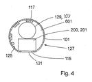
- the front end 107 may as well comprise at least one passive and/or active electronic component or microelectromechanical system 200 on the inside of the device 100 for invasive use.
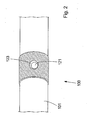
- an electronic component or microelectromechanical system 200 may e.g. comprise a pressure sensor 201, for example of the piezo electrical type, having contact with the surrounding body fluid through an access hole 115 in the device 100 for invasive use.
- the pressure sensor 201 may comprise a piezo electrical crystal.
- Another example may be a signal processing component, e.g. an amplifier used to amplify weak signals measured by the front end electrodes 111 or some other measuring element. For such a component there is no need for an access hole 115 to the surrounding body fluid.
- the at least one front end electrode 111 may also be used for stimulation with electrical voltage or current as in pacing applications or in the method described below, simultaneous measurement of pressure and volume of the heart's ventricles.
- Multiple electronic components and/or microelectromechanical systems 200 may be incorporated, it may for instance be advantageous to use several pressure sensors for diagnosis of stenosis in the coronary arteries to be able to measure the pressure on both sides of the stricture.
- the basis for the device 100 for invasive use is a flexible strip or foil, hereafter called support member 101.
- the support member 101 is advantageously long, thin and narrow and advantageously comprises a suitable insulating material, e.g. polyimide or a cycloaliphatic polyolefine.
- the material for the support member 101 is biologically-inert or bio-compatible.
- the device 100 for invasive use may also be covered with a layer of biocompatible hydrogel on the outside to reduce the friction and for improved biocompatibility, e.g. to avoid that blood coagulates on the outside of the device 100 for invasive use.
- the measures of the support member 101 may in one advantageous embodiment be 100 cm long, 1.5 mm wide and 50 micrometer thick. But as described before, the length, as well as the thickness and the width, may vary depending on the application.
- the width may be in the interval of 0,5-5 mm, more advantageously 1-3 mm, and the thickness may be in the interval of 10-200 micrometer, more advantageously 30-70 micrometer, in one particular embodiment 50 micrometer is used. Generally a greater thickness results in a more rigid device 100 for invasive use and a smaller thickness results in a less rigid one.
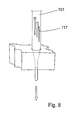
- electrically conductive lines and patterns 111, 113, 117 are arranged on both sides of the support member 101. At certain points there are holes, called via holes, 121 in the support member 101. The electrically conductive lines and patterns 111, 113, 117 on both sides of the support member 101 are electrically connected through the via holes 121.
- via conductors 123 connecting the electrically conductive lines and patterns 111, 113, 117 on both sides of the support member 101.
- the via conductors 123 comprise electrically conductive material on the walls of the via holes 121.
- the electrically conductive lines and patterns 111, 113, 117 may comprise a suitable metal, e.g. Copper or an electrically conductive polymer or another electrically conductive material.
- the support member 101 with the electrically conductive lines and patterns 111, 113, 117 placed thereon or attached thereto may be called a flexible printed wire board (flexible PWB) and the electrically conductive lines and patterns 111, 113, 117 can for instance be attached to the support member 101 with standard flexible printed wire board manufacturing equipment.
- the support member 101 comprises layers of electrically conductive lines and patterns 111, 113, 117 on both sides thereof (as in the embodiment described here) it is hereafter called double sided support member.
- first side 125 of the support member 101 there are electrically conductive lines or patterns 117 and on a second side 127 (the side that will become the "outside” of the device 100 for invasive use) there are electrically conductive areas or patterns 111, 113 that will serve as electrodes inside the body (front end electrodes 111) and as contacts to external electronic and data processing equipment (back end electrodes 113).
- the lines or patterns 117 on the first side 125 of the support member 101 connect the front end electrodes 111 and/or the at least one electronic component and/or at least one microelectromechanical system 200 with the back end electrodes 113.
- At least one electronic component and/or at least one microelectromechanical system 200 may be mounted, it/they may for example be flip-chip mounted or wire-bonded. Conducting adhesive, soldering or any other suitable attachment method may be used. In some cases packaged chips can be used, but normally the chips are unpackaged ("naked") to save space.
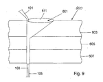
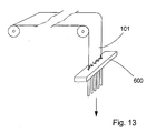
- the support member 101 is at least partly rolled up into a tube and simultaneously filled with adhesive or glue 601 that holds the support member 101 in a tube shape.
- Formation of the support member 101 at least partly into a tube is advantageously done by feeding the support member 101 through a hole 609 with a funnel-like opening 611 where the circumference of the hole 609 matches the width of the support member 101.
- the width of the support member 101 substantially equals the circumference of the hole 609.
- the circumference of the hole 609 equals the diameter of the hole 609 times ⁇ .
- the width of the support member 101 is the same as the circumference of the hole 609.
- a double sided support member 101 it is advantageous that the width of the support member 101 is slightly smaller than the circumference of the hole 609.
- an electronic component or microelectromechanical system 200 that is used for measurement or stimulation may be mounted over a hole or opening 115 in the support member 101 so as to have contact to the surrounding body tissue and/or fluids whereas signal processing components 200 are totally concealed. Parameters that may be measured include pressure, temperature, flow, pH, partial pressure of oxygen, mapping with ultra sound etc.
- microelectromechanical systems 200 it is also possible to combine different electronic components and/or microelectromechanical systems 200 to achieve multi functionality or to integrate several electronic components or microelectromechanical systems 200 of one kind to get extended functionality.
- One such example could be several pressure sensors 201 in order to improve diagnosis of stenosis in the coronary arteries.
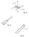
- Fig. 5 shows how a optical conductor 129 may be placed in the at least partly tube shaped device 100 for invasive use.
- the optical conductor protrudes from the back end of the device 100 for invasive use.
- Fig. 6a shows in detail the mounting of a pressure sensor 201 according to one suitable method.
- the bond pads 201a-201c on the pressure sensor 201 are respectively attached to the bond pads 118a-118c on the support member.
- the bond pads may be attached to each other by for example soldering or conducting adhesive.
- the pressure sensitive area 201d of the pressure sensor 201 may comprise a pressure sensor membrane 201e.
- the pressure sensitive area 201d of the pressure sensor 201 is placed in or over the access hole 115 in the support member 101.
- Fig. 6b shows in detail the mounting of a pressure sensor 201 according to a method that may be advantageous since it enables a strong or rigid fastening or mounting of the pressure sensor 201.
- the bond pads 201a-201c are placed on the upper side of the pressure sensor 201.
- Said bond pads 201a-201c are electrically connected to the electrically conductive lines 207 on the underside of the pressure sensor 201 by means of via holes 203a-203c which are provided with via conductors 205a-205c.
- the via conductors 205a-c comprise electrically conductive material on the walls of the via holes 203a-c.
- the bond pads 118a-118c on the support member 101 are placed adjacent or next to the mounted pressure sensor 201.
- the bond pads 118a-118c on the support member 101 are connected to respective bond pad 201a-201c on the pressure sensor 201 e.g. by means of wire bonding (wires 209a-209c), e.g. by using gold wires.
- wire bonding wires 209a-209c
- the pressure sensor 201 including the bonding wires 209 may be covered by e.g. silicone to protect the bonding wires and further strengthen the mounting of the pressure sensor 201.
- One advantage of using a support member 101 comprising electrically conductive lines or patterns 111, 113, 117 on both sides is that the back end electrodes 113 can be placed on the outside of the at least partly tube shaped device 100 for invasive use. This is an advantage when using the back end electrodes 113 to connect the device 100 for invasive use to external electronic and data processing equipment. Placing the back end electrodes 113 on the outside enables an uncomplicated construction of the contact for connecting the device 100 for invasive use to external electronic and data processing equipment.
- a device 100 for invasive use with the same functionality as described above but based on a multi layer concept where several support members 101, with one or two layers of electrically conductive lines and patterns 111, 113, 117 arranged thereon, are placed on top of each other.
- a device 100 for invasive use with the same functionality as described above but based on a single sided support member. That is, a support member with electrically conductive lines or patterns 111, 113, 117 on only one side.
- the conductive area for the front end and back end electrodes is put on the inside of the at least partly tube shaped support member 101 and access to the electrodes from the outside is arranged by removing part of the support member 101, preferably by laser ablation ( fig. 14 ).
- This approach has the advantage of avoiding fitting of electrically conductive patterns or lines 111, 113, 117 on both sides of the support member 101 which may be cumbersome over long distances.
- the back end electrodes 113 may in this case also be contacted with means of a contact that is inserted inside the at least partly tube formed support member 101. Another possibility is to let the part of the support member 101 where the back end electrodes 113 are placed to remain flat; i.e. not to form this part into a tube ( fig. 15 ). In this way the back end electrodes 113 may be contacted by means of a flat contact.
- Another feature that may be advantageous is to provide the device 100 for invasive use with an effective shielding by adding a mesh of thin metal lines on the outside of the support member 101 ( fig. 16 ). This may often be advantageous since signal levels (of the signals in the electrical conductors in the device 100 for invasive use) generally are low and the hospital environment often quite noisy electromagnetically. noisy meaning that the level of electromagnetic radiation in general is relatively high in a hospital environment.
- the device 100 for invasive use When the device 100 for invasive use is introduced into a canal, such as an artery or a vein, in the body it may be advantageous to introduce a catheter guide prior to the device 100 for invasive use which is then introduced inside the catheter guide.
- the catheter guide When the device 100 for invasive use is in its end position the catheter guide is withdrawn over the device 100 for invasive use.
- the catheter guide When the catheter guide is withdrawn it is necessary to hold the device 100 for invasive use so that it is not withdrawn together with the catheter guide. Consequently, the device 100 for invasive use has to be long enough (basically twice as long as needed from a clinical point of view) so that it can be held in position during the withdrawal of the catheter guide.
- the main part of the device 100 for invasive use that is outside of the body is only used for this purpose, to enable the device 100 for invasive use to be kept in position while the catheter guide is being withdrawn.
- devices for invasive use such as catheters, have been manufactured as fully functional devices to their entire length. This may be disadvantageous since the part of the catheter being outside of the body often is relatively long, around 100 cm is not unusual, and may get damaged or be hindering when the patient is treated, examined or otherwise handled.
- the support member 101 has the full length needed, but the back end electrodes 113 are placed close to the point where the device 100 for invasive use enters the body (or the point where the device 100 for invasive use protrudes from the body through the insertion hole).
- the part of the device 100 for invasive use that extends behind the back end electrodes 113 may comprise merely the support member 101 and it may be cut off or otherwise separated from the rest of the device 100 for invasive use after the catheter guide has been withdrawn.
- the separation of the "non-functional" part 135 may be facilitated by means of for example a perforation 137.
- the device 100 for invasive use only extends a short distance outside the body and the risk that the device 100 for invasive use should be hindering or damaged is reduced substantially.
- To use a catheter guide is a commonly used procedure.
- the device 100 for invasive use described herein has been verified by the design and manufacture of a prototype device 300 for the simultaneous measurement of pressure and volume of the heart's left ventricle.
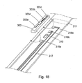
- the prototype device 300 is shown in figs. 17 and 18 .
- the prototype device 300 is described in detail below.
- a prototype support member 301 made of a flexible material was provided with electrically conductive lines and patterns 311, 313, 317, in the form of conductor lines 317 on the first side 325 and electrodes 111, 113 on the second side 327 of the prototype support member 301, using standard technology.
- the dimensions of the prototype support member 301 were: length 35 cm, width 2,1 mm and thickness 50 ⁇ m.
- conductor lines 317a-317g were placed/manufactured ( fig. 17 ), 3 of them terminating near a hole 315 over which a pressure sensor chip 303 later was to be mounted (soldered).
- a soldering pad 318a-318c in electrical contact with respective line, was placed.
- the other 4 lines were terminated at via holes 321 connecting the lines to front end electrodes 311a-311d on the second side 327 of the prototype support member 301 ("outside" of the finished device).
- the via holes 321 connect the lines to the outside electrodes 311, 313 by means of electrically conductive material (via conductors) 323 on the walls of the via holes 321.
- the front end electrodes 311a-311d were placed with two electrodes on each side of the pressure sensor chip 303. In this embodiment 4 front end electrodes 311 were used but depending on the measurement method or application fewer or more electrodes may be used.
- the arrangement of the electrodes is adapted to the measurement method or application in question.
- the metal copper was used, approximately 20 ⁇ m thick.
- the conductor lines 317 were covered with a layer of a suitable material (for example tin or silver+gold) to enable soldering of the pressure sensor chip 303.
- the electrodes 111, 113 were covered with a layer of a material suitable (for example gold) to make the device 100 for invasive use suitable to be inserted into the body: That is, to make the device 100 for'invasive use biocompatible or biologically inert.
- the conductor lines 317 were 100 ⁇ m wide with distances of 100 ⁇ m between the lines.
- the bond pads 303a-303c on the pressure sensor 303 were respectively attached to the bond pads 318a-318c on the prototype support member 301.
- the pressure sensitive area 303d of the pressure sensor 303 may comprise a pressure sensor membrane 303e (not shown) Solder paste was applied to the bonding pads 318a-318c ( fig. 18 ) by screen printing and the pressure sensor chip 303 was put in place with standard surface mounting electronic production equipment. Subsequently the chip was soldered in a furnace using a suitable temperature curve or profile with a peak temperature of about 230° C.
- the prototype support member 301 was fed through a funnel-like opening 611 and a through-hole 609 in a tool or jig 600 ( figs. 8-10 ) where the diameter of the through-hole 609 was 0,7 mm.
- the funnel-like opening 611 was heated in the upper part to 140°C where also a suitable adhesive was provided, in this case PolyCaproLacton (PCL) was used.
- PCL PolyCaproLacton
- This adhesive melted and filled the interior of the support member while it was formed to a tube by feeding it through the tool or jig 600.
- the lower portion of the through-hole 609 was cooled by a Peltier-cooler to enable the adhesive to crystallize.
- the pressure sensor chip 303 was of a kind adapted to be contained in the small space inside the tube shaped prototype support member 301.
- a thin, long rod was formed with a diameter and flexibility suitable for the use as a device for invasive use for insertion through a vein in the neck to reach the right ventricle of the heart or through the aorta to reach the left ventricle of the heart.
- the front end of the device When the front end of the device is placed in either of the heart's ventricles it can be used to monitor pressure/volume loops.
- the length of the prototype device 300 needs to be increased to make it suitable for some clinical applications but this can be accomplished with existing techniques for the production of flexible printed wire boards in a way easily derivable for the person skilled in the art.
- the device 100 for invasive use may be provided with a reinforcing or rigidifying element 103 on the inside of the at least partly tube shaped support member 101.
- the reinforcing or rigidifying element 103 may be provided along the entire length of the device 100 for invasive use or merely along a portion of the length of the device 100 for invasive use.
- the reinforcing or rigidifying element 103 may for example comprise a wire or string made of for example metal or polymer, and/or the reinforcing or rigidifying element 103 may comprise the solidified or crystallized adhesive or glue, for example the solidified or crystallized PolyCaproLakton, PLC.
- the reinforcing or rigidifying element 103 may also comprise a lumen. If the reinforcing or rigidifying element 103 comprises a lumen (or at least one lumen) it may be used for taking samples from inside the body or for distributing substances, like medicine, to the body.
- the rigidity of the device 100 for invasive use can be adapted to different applications, for example the application where the device 100 for invasive use is inserted to the desired location directly through tissue.
- the device 100 for invasive use may for example be inserted through myocardium and subsequently withdrawn without causing trauma.
- To vary the rigidity of the reinforcing or rigidifying element 103 may be an advantage since a well adapted degree of rigidity may positively influence the usability of the device 100 for invasive use in a certain application.
- the reinforcing or rigidifying element 103 may be double as long as the support member 101 and extend beyond the back end 109 of the device 100 for invasive use (see fig. 3b ). After insertion of the device 100 for invasive use the part of the reinforcing or rigidifying element 103 extending beyond the back end 109 may be cut off.
- the reinforcing or rigidifying element 103 may also extend ( e.g . about 5-30mm, advantageously about 7-13 mm) beyond the front end 107 of the support member 101 and so replacing or complementing the soft tip 105 (see fig. 1 ).
- the reinforcing or rigidifying element 103 extends beyond the front end 107 of the support member 101 it is advantageous that the extending part of the reinforcing or rigidifying element 103 is bent, for example by using heat, and biocompatible.
- the length, diameter, rigidity, curvature and other characteristics of the part of the reinforcing or rigidifying element 103 extending beyond the front end 107 of the support member 101 are adapted to the application or use in question.
- the reinforcing or rigidifying element 103 may in this way enable an effective and precise guidance of the device 100 for invasive use e.g. in a network of blood vessels.
- the device 100 for invasive use is used for monitoring parameters in the ventricle/s of the heart it may be advantageous to provide the device 100 for invasive use with a reinforcing or rigidifying element 103 since the device 100 for invasive use is bent very frequently as a result of the pumping motion of the heart. Without a reinforcing or rigidifying element 103 the device 100 for invasive use may be damaged by the frequent bending. This of course also applies to other applications where the device 100 for invasive use is subjected to frequent bending.
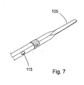
- the device 100 for invasive use may also be advantageous to provide the device 100 for invasive use with a soft tip 105 integrated at the front end of the device 100 for invasive use ( fig. 7 ).
- the tip 105 is advantageously formed when cutting the flexible support member 101 that is used for the device 100 for invasive use. In this way the tip 105 constitutes an integrated part of the device 100 for invasive use.
- the tip 105 is advantageous when the device 100 for invasive use is inserted into the body, for example when the device 100 is inserted into a ventricle of the heart. Also when the device 100 for invasive use has been inserted and is in its end position the soft tip 105 ensures that the surrounding tissue, muscle or artery or vein is not damaged or penetrated.
- the support member 101 is around 50 micrometer thick and the tip 105 is approximately 0.7mm wide, ca 30mm long, and includes a fine graded transition to the approximately 2mm wide part of the support member 101. These measures make the tip 105 soft and prevents that the heart is injured or disturbed (for example arrhythmia) when the device 100 for invasive use e.g. is inserted, withdrawn or in its end position.
- the tip 105 is an integrated part of the device 100 for invasive use, for example the tip 105 can not fall off.
- the devices for invasive use (often called catheters) known from the background art separate tips of for example platinum have been used and in some cases they have fallen off while the device was inside the body. This is a disadvantage since it can create a dangerous situation for the patient and/or render the examination that is carried out with the device difficult.
- the device 100 for invasive use may be attached to another structure, e.g. a medical device such as a feeding probe.
- a medical device such as a feeding probe.
- nerve signals from the diaphragm may be measured with the at least one front end electrode 111 of the device 100 for invasive use.
- the attachment may be accomplished by means of for example an adhesive or some other attachment means.
- an elongated support member 101 is at least partly brought into a tube shape and the inside of the tube shaped support member 101 is at least partly sealed from the outside.
- the support member 101 has at least one electrical conductor on one or both sides of the support member 101 and may advantageously be equipped with at least one electronic component and/or at least one microelectromechanical system 200. It may be an advantage to mount the at least one electronic component and/or at least one microelectromechanical system 200 on the inside of the at least partly tube shaped support member 101 but at least one component or system may also be mounted on the outside of the a least partly tube shaped support member 101, especially if it is integrated in the support member 101.
- the at least one electronic component and/or at least one microelectromechanical system 200 is mounted on the support member 101 before the support member 101 is, at least partly, formed into a tube shape.
- the device 100 for invasive use is equipped with a reinforcing or rigidifying element 103 on the inside of the at least partly tube shaped support member 101.
- the support member 101 is provided with a tip 105 at at least one of the ends of the support member.
- the tip 105 is narrower than the rest of the support member and may have a length of approximately 10 to 50 mm, preferably 15 to 30 mm.
- a jig or tool 600 made out of a block of material like metal or plastic is used.
- the metal used may for example be steel, brass, copper or any other alloy.
- a suitable plastic may for example be polymethacrylate, known as PlexiglassTM.
- the jig or tool 600 is provided with a small hole 609 having a funnel-like opening 611.
- the hole 609 and the funnel-like opening 611 are adapted not to damage the support member 101 or the conductive patterns 111, 113 or other elements provided on the second side 127 of the support member 101.
- a lining be provided in the hole 609 and/or funnel-like opening 611.
- the tip 105 of the support member 101 is.threaded trough the funnel-like opening 611 and the small hole 609.
- the opening 611 is filled with an adhesive or glue 601, it may be advantageous to use PolyCaproLacton (PCL) which has a good adhesion to polyimide.
- the adhesive or glue 601 may be distributed by means of a dispenser. Generally, an adhesive 601 is selected that has a good adhesion to the material of the support member 101. The adhesion between the adhesive 601 and the support member 101 needs to be good to maintain the support member 101 in a tube shape. The adhesive 601 is melted and fills the support member 101.
- the reinforcing or rigidifying element 103 may comprise the solidified adhesive material, a separate reinforcing or rigidifying element or a combination of the solidified adhesive material and the separate reinforcing or rigidifying element.
- the separate reinforcing or rigidifying element e.g. a wire or the like, is placed on the inside of the support member 101. The principle of how the support member 101 is formed is shown in figs. 8 and 9 . If there are via holes 121 in the support member these will filled with adhesive material as the support member 101 is being fed through the tool 600.
- the adhesive material will fill the via holes 121 completely and will substantially be in line with the outside surface of the support member 101. If the device 100 for invasive use is not covered with a biocompatible material, like a biocompatible hydrogel, it is advantageous that the adhesive material used is biocompatible.
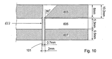
- the jig or tool 600 comprises three layers, an upper heating layer 603, a middle insulation layer 605 and a bottom cooling layer 607.
- a hole 609 with a diameter of 0.7mm passes through the three layers in the jig or tool 600.
- the upper layer 603 is heated to a temperature between +75 and +200°C and the lower layer 607 is cooled to a temperature between -10 and +25°C.
- a higher heating temperature requires a lower cooling temperature, but it may be advantageous to use a temperature of +140°C in the upper layer 603 and +5°C in the lower layer 607.
- the middle layer 605 is used as insulation layer.
- the support member 101 is 2mm wide and at least one of the ends of the support member 101 is provided with a 0.7mm wide tip 105.
- One of the tips is, in an advantageous embodiment, ca 30 mm long, and includes a fine graded transition to the 2mm wide part of the support member 101. That tip 105 is pulled down into the funnel-like opening 611, which has a maximum diameter of 7.9 mm and connects to the hole 609 having a diameter of 0.7 mm. It may be advantageous to use a steel wire loop that is threaded with the tip 105 of the support member 101 to pull down the support member 101 through the hole 609.
- the width of the support member 101 substantially corresponds to the diameter of the hole 609 times ⁇ .
- the support member 101 is formed into a tube without any overlap so that one of the longer edges of the support member 101 abuts or faces the other longer edge of the support member 101.
- the funnel-like opening 611 is shaped as shown in figs. 9 and 10 .
- One side of the funnel-like opening 611 is substantially vertically leading down to the hole 609 and the inclination-angle of the funnel-like opening 611 gets gradually smaller as one moves from the substantially vertical side towards the opposite side of the funnel-like opening 611 where the inclination-angle is approximately 40-70 degrees, advantageously 60 degrees.
- the hole 609 may be lined, e.g. with a lining tube 613 as shown in fig. 10 .
- the lining of the hole 609 is advantageous since it is a convenient way to ensure that the hole 609 has a smooth surface that will not damage the support member 101.
- the tube 613 extends a certain distance (in fig.
- the lining tube 613 has an outer diameter of 2mm, which of course is just an example and may be varied depending on the circumstances.
- the figuring 0,7mm denotes the diameter of the support member 101.
- the front part of the support member 101 is placed with the side that will later be the outside of the device 100 for invasive use in contact with the substantially vertical side of the funnel-like opening 611.
- the rest of the support member 101 is leaned backwards from the funnel-like opening 611 with an angle of about 40-60°. This is done by attaching a thread to the free end of the support member 101 and letting it rest on a stick fastened a few decimetres diagonally behind the jig or tool 600.
- the support member 101 When the tip 105 is pulled, the support member 101 is folded to fit into the hole 609 and the tip 105 is pulled until a length of approximately 5-10mm of the 2mm wide folded support member 101 has exited the hole 609.
- the support member 101 By letting the support member 101 lean backwards it is forced to stay close to the approximately vertical side of the funnel-like opening 611 to prevent adhesive or glue 601 from flowing down into the hole 609 on the outside of the support member 101. If adhesive 601 would attach to the outside of the support member 101 that could interfere with the access hole 115 and the membrane 131 that may be placed in the access hole 115.
- the leaning also makes the support member 101 automatically fold with the side, which later will be the inner wall of the catheter, on its inside.
- the clip is coupled to a pulling mechanism by a thread, the pulling mechanism may for example be driven by a motor such as a DC-motor.
- the pulling mechanism When the PCL is melted, it becomes transparent and soft. Then the pulling mechanism is activated or started and pulls the support member 101 through the hole 609 at a speed of up to about 7cm/min or faster but advantageously 1-5 cm/min and more advantageously about 2.8cm/min. The speed depends of the heating and cooling temperatures. That is because the pulling speed has to be slow enough to let the melted PCL flow into the support member 101 and also to let the PCL crystallize while passing the cooling part of the hole 609.
- the clip may be held in place with a stiff board, which the clip leans towards as it moves downwards.
- the support member 101 When the whole support member 101 has passed through the hole 609, the support member 101 is caught by hand and released from the clip. It may in some cases be desirable not to form the last part of the support member 101 into a tube shape. In this case the supply of adhesive 601 is simply stopped when the end of the support member 101 is approaching and the last part of the support member 101 is drawn through the jig or tool 600 without supply of adhesive 601.
- the support member 101 may also be possible to pull the support member 101 through the tool or jig 600 at an angle so that the joint between the edges of the support member 101 forms a spiral so that the edges of the support member 101 overlap one another to provide a more rigid device 100 for invasive use. It may also be possible to make the spiral shape so that there is no overlap of the side edges of the support member 101. In this way, glue or adhesive 601 may be applied to the inside surface close to the side edges to form the support member 101 into a tube shape that is more rigid than when the joint between the side edges is straight.
- An alternative to filling the at least partly tube shaped support member 101 with glue or adhesive 601 may be to feed a meltable string of solid glue or adhesive or another suitable polymer/additive with appropriate diameter through the funnel-shaped opening 611 and hole 609 simultaneously with the support member 101.
- a layer or primer may be applied to the inside of the support member 101 to enhance the adhesion between the meltable string and the inner surface of the support member 101 during the roll-up process.
- the layer may also protect the at least one electronic component and/or at least one microelectromechanical system 200 from the glue or adhesive 601 if necessary. Examples of such layers are Polycaprolacton lacquer and Parylene.
- Parylene is the product Parylene HTTM (Specialty Coating Systems, Indianapolis, USA).
- the meltable string may melt (partly, only on the surface, or fully) and fill the support member 101 in the upper end and be solidified in the lower end as described above. Any other method of at least partly forming a tube of the support member 101 may also be used, even though the method described here may be advantageous.
- the jig or tool 600 may be provided with welding equipment that welds the edges of the support member 101 to each other as the support member 101 is drawn through the jig or tool 600.
- the support member 101 may also be provided with a separate reinforcing or rigidifying element 103 as the support member 101 is drawn through the jig or tool 600.
- the reinforcing or rigidifying element 103 may advantageously be provided on the inside of the at least partly tube shaped support member 101.
- the reinforcing or rigidifying element 103 may be attached to the clip together with the tip 105.
- the reinforcing or rigidifying element 103 may comprise at least one optical fibre or waveguide 129 for providing a communication possibility between the back end electrodes 113 and the at least one electronic component and/or at least one microelectromechanical system 200 and/or at least one front end electrode 111 of the device 100 for invasive use.
- the at least one optical fibre or waveguide may be used in addition to, or instead of, the electrically conductive lines or patterns 117.
- the front end of the support member 101 may be sealed with an adhesive, by means of the reinforcing or rigidifying element 103, or by means of a plug of a suitable material.
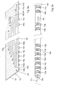
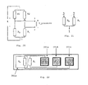
- the support members 101 may be manufactured simultaneously in great numbers.
- support members 101 are manufactured from sheets or panels 133 of a suitable material as shown in Fig. 11 . Common widths of the panels or sheets 133 are 30 or 45cm, which allows hundreds of support members 101 (approximately 1-2 mm wide) to be manufactured simultaneously.
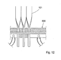
- the support members 101 are separated by perforations (done for example by milling or laser ablation) to make it easy to separate them. This allows simultaneous formation of several devices 100 for invasive use as depicted in Fig. 12 . Water may be used to cool the bottom part or cooling layer 607 of the tool or jig 600. It is also possible to make the production continuous as indicated in Fig.
- the support members 101 are preferably separated from one another by a suitable perforation or other suitable technologies.
- the perforation may be added before the perforated sheet or panel 133 enter the tool or jig 600.
- two standard methods are combined with the device 100 for invasive use described herein in a continuous production process.
- the support members 101 are subjected to standard process steps used today by manufacturers of flexible printed wire boards, such as via drilling, pattern formation by lithography and etching. Conductors may also be formed by ink jet printing or in other ways.
- the at least one electronic component and/or at least one microelectromechanical system 200 is attached by standard pick-and-place equipment using conducing glue, soldering or some other method.
- the sheet or panel 133 is fed into a tool or jig 600 with several parallel holes 609 with funnels-shaped openings 611.
- the feeding mechanism is omitted in the figure. This would constitute a fully continuous process.
- Devices 100 for invasive use can be cut off in batches after passage of the tool or jig 600.
- the device 100 for invasive use described herein is manufactured with proven methods used in electronics production, apart from the formation of the support member 101 into a tube shape, or at least partly into a tube shape.
- this latter step can be performed so as to give the finished device 100 excellent mechanical properties and where the device 100 has a construction of low complexity. This gives the device 100 high reliability and it can be manufactured cost effective and still have outstanding electrical and mechanical properties.
- the construction is relatively simple. Thereby reliability can be improved.
- the support member (101) itself constitutes a device suitable for invasive use. Since the construction is relatively simple the device 100 for invasive use may also be manufactured relatively inexpensive which facilitates the use of the device 100 for invasive use as a single use article.
- the manufacturing process brings advantages for example in terms of automation.
- the manufacturing process is also easy to implement in a bigger scale since several devices can be manufactured in parallel.
- the support member 101 may also be advantageous to provide the support member 101 with a sharp point for facilitating the insertion of the device 100 for invasive use through tissue to an organ.
- the sharp point may be in the form of a needle.
- the device 100 for invasive use is adapted to extend from an organ at least to a point of surgical incision.
- the device 100 for invasive use is adapted to extend from the heart at least to the groin.
- the device 100 for invasive use may be used as part of a system for monitoring, examining or treating a patient.
- a system 700 for monitoring the heart will be described (see in particular figs. 3 , 19-25 ).
- the system 700 enables the function of the left ventricle of the heart to be monitored in real time, during for example invasive heart examination, heart operation or post operative treatment.
- the system 700 comprises the device 100 for invasive use, an accompanying contact (not shown) and equipment for signal processing and displaying.
- a device 100 for invasive use which is thin, supple and comprises a soft tip 105, is introduced or inserted through an artery in the groin so that the front end 107 of the device 100 for invasive use is placed in the left ventricle of the heart.
- a catheter guide is advantageously used when the device 100 for invasive use is introduced.
- the device 100 for invasive use may be inserted into the femoral aorta and pushed through the aorta and into the left ventricle of the heart.
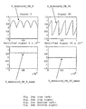
- volume and pressure in the left ventricle of the heart can be measured and a Pressure- Volume diagram can be displayed.
- a physician can in this Pressure- Volume diagram read or derive parameters for the function of the heart and diagnose illness or malfunction.
- the device 100 for invasive use is in this case implemented as a multi-functional device combining means for conductance/impedance measurement (front end electrodes 111) with a pressure sensor 201.
- the volume measurement functions as an impedance measurement.
- four front end electrodes 111a-111d are placed, two of them excitation electrodes 111a, 111d and between these, two measurement electrodes 111b, 111c.
- the device 100 for invasive use is placed so that the fore part is substantially aligned with the longitudinal axis of the left ventricle.
- the excitation electrodes 111a, 111d are placed to be on a level with the apex of the heart (apex cordis) and the base of the heart (basis cordis).
- the two excitation electrodes 111a, 111d are fed with a voltage U excitation so that an alternating current I excitation with the frequency 20 kHz and the intensity 100 micro-ampere flows between the two excitation electrodes, this is in accordance with the standard IEC-601.
- Advantageously alternating current is used to avoid interference with cardiac electro-physiology.
- An electromagnetical field will be generated in the left ventricle, which creates a voltage U measured that may be measured with the two measurement electrodes 111b, 111c.
- the impedance Z meas.elec. will in turn be dependent on the volume in the ventricle.
- the measured voltage U measured is amplified, filtered, demodulated, used to compute the volume V using equations (1) and (2), and the signal is then subjected to an analog-to-digital (A/D) conversion so that it conveniently can be presented graphically.
- A/D analog-to-digital
- the demodulation follows the principle of phase sensitive rectifier which means that the phase of the AC signal U measured is compared to U excitaion and the signal Umeasured is converted into two DC-voltage levels where one correspond to the real valued voltage over the impedance and the other to the imaginary valued part.
- the impedance is the impedance present between the two measurement electrodes.
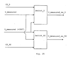
- the demodulation works as follows. The signal U measured is divided into two signals where one is phase shifted 180°. Both signals U measured and Umeasured (+180°) are then switched in two switches, switch_0 and switch_90.
- Each of the two switches are controlled by a control pulse, where one control pulse (CP_0) has the same phase as the signal U excitation and the other (CP_90) is phase shifted +90° in relation to U excitation .
- Switch_0 is controlled by CP_0 and switch_90 is controlled by CP_90. Both switches have both the signals U measured and Umeasured (+180°) as inputs. The switches will then let U measured pass when the control pulse is high (logic 1), and let U measured (+180°) pass when the control pulse is low (logic 0). For both of these output signals from the switches (U measured_SW_0 and U measured_SW_90 ) the mean value is computed (U measured_SW_0_mean and U measured_SN_90_mean ).
- the system works well as an impedance meter and measures the impedance with good accuracy approximately +0.5 ohm.
- the measurement of the volume is however an approximation and is dependent on that the system is adjusted for a specific positioning of the device 100 for invasive use.
- the fore part of the device 100 for invasive use will be placed along the vertical axis of the left ventricle.
- the accuracy of the volume measurement will be approximately ⁇ 3 ml, but be better for lower volumes (under 120 ml).
- the impedance of the blood is much lower than that of the surrounding tissues which is vital for the measurement to work. However, the surrounding tissues will give a contribution to the measured impedance which will have to be compensated for.
- Another method is to calibrate the system to the patient's volume measured by other measurements, for example the measurement of stroke volume done with thermo dilution or ultrasound.
- a pressure sensor 201 is used for the pressure measurement.
- the pressure sensor 201 is mounted on the device 100 for invasive use between the two measurement electrodes 111b and 111c that is used for the volume measurement.
- the pressure sensor 201 is a MEMS-chip (Micro Electro Mechanical Systems) that in this embodiment comprises two resistors, R p and R t .
- R p Micro Electro Mechanical Systems
- the pressure sensor 201 contains a half bridge that is connected to two other resistors R 1 and R 2 to form a complete Wheatstone bridge.
- the resistors R 1 and R 2 may for example be incorporated in the unit for Amplification or Filtering or they may be placed on the device 100 for invasive use.
- Figs. 3 and 17 show the embodiment where the resistors R 1 and R 2 are placed outside the device 100 for invasive use.
- a voltage (E in fig. 20 ) of the direct current type, a DC voltage, of approximately 1-2 Volts is connected to the Wheatstone bridge and the output signal U pressure from the Wheatstone bridge will be proportional to the pressure exerted on the pressure sensor 201.
- the sensitivity of the pressure measurement depends on the type of pressure sensor 201 used.
- the sensitivity may vary from 28.6 ⁇ V/V/kPa to 102,1 ⁇ V/V/kPa.
- Four pressure sensors based on the same principle have been used for evaluation.
- the sensitivity of the pressure sensors is dependent on their geometry. The larger the sensor is, the larger is its pressure sensitive membrane and therefore its sensitivity.
- the output signal U pressure from the pressure sensor 201 is amplified, filtered and subjected to an analog-to-digital (A/D) conversion so that it conveniently can be presented graphically (see fig. 19 ).
- A/D analog-to-digital
- Varying values of the components in the pressure sensor 201, for example varying resistance values of the resistors, will cause imbalance in the Wheatstone bridge. This imbalance can not be neglected but has to be compensated for, such an imbalance may influence the measured/computed pressure value with as much as +/- 20 kPa.
- calibration data for each device 100 for invasive use are saved in a memory placed in a contact (not shown) that is used to connect the device 100 for invasive use to the equipment for signal processing and displaying.
- Each device 100 for invasive use is provided with a dedicated contact containing calibration data for that particular device 100 for invasive use.
- the calibration data will include the sensitivity of the pressure sensor 201 and its contribution to the imbalance in the Wheatstone bridge. It is advantageous to calibrate the system to the atmospheric pressure prevailing when the device 100 for invasive use is used. When calibrated the accuracy for the pressure measurement will be good, approximately +/- 133 Pa. An accuracy in this range is advantageous for the application of monitoring heart function.
- R p is the pressure sensitive resistor.
- R t is a reference resistor with the same temperature dependence as R p and hence has the function of compensating for temperature.
- the pressure sensor 201 is connected to the resistors R 1 and R 2 and to ground by means of three connectors, for example bond pads, 201a-201c.
- the numbers 1, 2 and 3 denotes the connection points for the connectors 201a-201c ( figs. 6 , 20-22 ).
- the frame around the resistor R p in fig. 22 symbolises the pressure sensitive area 201d (which may include a pressure sensor membrane 201e) on the pressure sensor 201.
- the use of the device 100 for invasive use brings advantages since several examinations relating to invasive use can be done more easily and/or to a lower cost, and also examinations that have not been able to perform previously can now be performed with the device 100 for invasive use described herein.
Landscapes
- Health & Medical Sciences (AREA)
- Life Sciences & Earth Sciences (AREA)
- Engineering & Computer Science (AREA)
- Veterinary Medicine (AREA)
- Public Health (AREA)
- Physics & Mathematics (AREA)
- General Health & Medical Sciences (AREA)
- Animal Behavior & Ethology (AREA)
- Biomedical Technology (AREA)
- Heart & Thoracic Surgery (AREA)
- Surgery (AREA)
- Molecular Biology (AREA)
- Medical Informatics (AREA)
- Pathology (AREA)
- Biophysics (AREA)
- Cardiology (AREA)
- Nuclear Medicine, Radiotherapy & Molecular Imaging (AREA)
- Physiology (AREA)
- Radiology & Medical Imaging (AREA)
- Mechanical Engineering (AREA)
- Vascular Medicine (AREA)
- Microelectronics & Electronic Packaging (AREA)
- Optics & Photonics (AREA)
- Measurement And Recording Of Electrical Phenomena And Electrical Characteristics Of The Living Body (AREA)
- Electrotherapy Devices (AREA)
- Media Introduction/Drainage Providing Device (AREA)
Claims (18)
- Vorrichtung (100) zur invasiven Verwendung, die ein Trägerelement (101) umfasst, das ein flexibles Material enthält, wobei:a. das Trägerelement (101) mindestens eine Schicht aus mindestens einer elektrisch leitfähigen Leitung oder mindestens einem elektrisch leitfähigen Muster (117) darauf umfasst;b. das Trägerelement (101) zumindest teilweise als eine längliche Röhre geformt ist, und das Innere des Trägerelements (101) zumindest teilweise gegenüber dem Äußeren des Trägerelements (101) abgedichtet ist;c. mindestens eine elektrisch leitfähige Leitung oder mindestens ein elektrisch leitfähiges Muster (117) der mindestens einen Schicht auf der Innenseite der länglichen Röhre (101) verläuft; undd. das Trägerelement (101) mindestens ein Erfassungs-, Stimulations- und/oder Verarbeitungselement (111, 113, 200, 201) umfasst, und wobeidas Trägerelement (101) mindestens eine Öffnung (115) durch die Längswand der länglichen Röhre aufweist und mindestens eins von dem mindestens einen Erfassungs-, Stimulations- und/oder Verarbeitungselement (220, 201) nach der mindestens einen Öffnung (115) ausgerichtet ist.
- Vorrichtung (100) zur invasiven Verwendung nach Anspruch 1, wobei das Trägerelement (101) zumindest teilweise mit einem flexiblen elastischen Material wie einem Klebstoff oder einem Polymer (601) gefüllt ist.
- Vorrichtung (100) zur invasiven Verwendung nach Anspruch 1, wobei das Trägerelement (101) vollständig mit einem flexiblen elastischen Material wie einem Klebstoff oder einem Polymer (601) gefüllt ist.
- Vorrichtung (100) zur invasiven Verwendung nach Anspruch 1, wobei das Innere des Trägerelements (101) gegenüber dem Äußeren des Trägerelements (101) vollständig abgedichtet ist.
- Vorrichtung (100) zur invasiven Verwendung nach Anspruch 1, wobei die Vorrichtung (100) zur invasiven Verwendung angepasst ist, mittels chirurgischen Eingriffs provisorisch in einem Körper angeordnet zu werden, um die Funktion eines Organs zu überwachen oder zu beeinflussen.
- Vorrichtung (100) zur invasiven Verwendung nach Anspruch 5, wobei die Vorrichtung (100) zur invasiven Verwendung angepasst ist, mittels chirurgischen Eingriffs provisorisch in einem Körper angeordnet zu werden, um die Funktion eines Herzens zu überwachen oder zu beeinflussen.
- Vorrichtung (100) zur invasiven Verwendung nach Anspruch 1, wobei die benachbarten Ränder des Trägerelements zumindest teilweise durch Schweißen verbunden sind.
- Vorrichtung (100) zur invasiven Verwendung nach Anspruch 1, wobei die benachbarten Ränder des Trägerelements (101) zumindest teilweise durch einen Klebstoff verbunden sind.
- Vorrichtung (100) zur invasiven Verwendung nach Anspruch 1, wobei das mindestens eine Erfassungs-, Stimulations- und/oder Verarbeitungselement mindestens ein elektronisches Bauteil oder mikroelektromechanisches System (200) umfasst, das an der Innenseite des zumindest teilweise röhrenförmigen Trägerelements (101) vorgesehen ist.
- Vorrichtung (100) zur invasiven Verwendung nach Anspruch 9, wobei das mindestens eine elektronische Bauteil oder mikroelektromechanische System (200, 201) aus einem Drucksensor, einem Spannungssensor, einem pH-Sensor, einem Temperatursensor, einem Gassensor, einem Bauteil zum Nachweisen oder mengenmäßigen Bestimmen eines Reagens und einer Medikamentenabgabevorrichtung ausgewählt ist.
- Vorrichtung (100) zur invasiven Verwendung nach Anspruch 1, wobei mindestens eine Elektrode (111, 113) an der Außenseite der länglichen Röhre (101) platziert ist.
- Vorrichtung (100) zur invasiven Verwendung nach Anspruch 1, wobei mindestens eine Elektrode (111, 113) an der Innenseite der länglichen Röhre (101) platziert ist.
- Vorrichtung (100) zur invasiven Verwendung nach Anspruch 11 oder 12, wobei mindestens vier Elektroden (111, 113) vorgesehen sind, wobei die mindestens vier Elektroden einen Volumensensor darstellen.
- Vorrichtung (100) zur invasiven Verwendung nach Anspruch 1, wobei mindestens ein Verstärkungs- oder Versteifungselement (103) an der Innenseite des Trägerelements (101) vorgesehen ist.
- Vorrichtung (100) zur invasiven Verwendung nach Anspruch 14, wobei das mindestens eine Verstärkungs- oder Versteifungselement (103) über ein Ende oder beide Enden des Trägerelements (101) hinausgeht.
- Vorrichtung (100) zur invasiven Verwendung nach Anspruch 14 oder 15, wobei das mindestens eine Verstärkungs- oder Versteifungselement (103) eine Glasfaser oder einen Wellenleiter (129) umfasst.
- Vorrichtung (100) zur invasiven Verwendung nach einem der Ansprüche 9 oder 10, wobei mindestens eine Glasfaser oder mindestens ein Wellenleiter (129) an der Innenseite des Trägerelements 101 vorgesehen ist.
- Vorrichtung (100) zur invasiven Verwendung nach einem der Ansprüche 9, 10 oder 17, wobei das mindestens eine elektronische Bauteil oder mikroelektromechanische System (200, 201) angrenzend an ein vorderes Ende (107) des Trägerelements (101) und in funktionsmäßigem Kontakt mit der mindestens einen elektrisch leitfähigen Leitung oder dem mindestens einen elektrisch leitfähigen Muster (117) oder der mindestens einen Glasfaser oder dem mindestens einen Wellenleiter (129) platziert ist.
Applications Claiming Priority (2)
| Application Number | Priority Date | Filing Date | Title |
|---|---|---|---|
| US80365806P | 2006-06-01 | 2006-06-01 | |
| PCT/SE2007/000528 WO2007139479A1 (en) | 2006-06-01 | 2007-05-31 | Tubular catheter for invasive use and manufacturing method therefor |
Publications (2)
| Publication Number | Publication Date |
|---|---|
| EP2032201A1 EP2032201A1 (de) | 2009-03-11 |
| EP2032201B1 true EP2032201B1 (de) | 2013-04-03 |
Family
ID=38778896
Family Applications (1)
| Application Number | Title | Priority Date | Filing Date |
|---|---|---|---|
| EP07748192A Not-in-force EP2032201B1 (de) | 2006-06-01 | 2007-05-31 | Rohrförmiger katheter für invasive verwendung und herstellungsverfahren dafür |
Country Status (4)
| Country | Link |
|---|---|
| US (1) | US20090143651A1 (de) |
| EP (1) | EP2032201B1 (de) |
| JP (1) | JP5603071B2 (de) |
| WO (1) | WO2007139479A1 (de) |
Cited By (1)
| Publication number | Priority date | Publication date | Assignee | Title |
|---|---|---|---|---|
| US10178960B2 (en) | 2013-02-11 | 2019-01-15 | St. Jude Medical, Atrial Fibrillation Division, Inc. | Printed electrode catheter |
Families Citing this family (58)
| Publication number | Priority date | Publication date | Assignee | Title |
|---|---|---|---|---|
| CA2932956C (en) | 2006-08-03 | 2020-04-14 | Christoph Scharf | Method and device for determining and presenting surface charge and dipole densities on cardiac walls |
| KR20090067744A (ko) | 2007-12-21 | 2009-06-25 | 엘지전자 주식회사 | 연성 필름 |
| KR100896439B1 (ko) * | 2007-12-26 | 2009-05-14 | 엘지전자 주식회사 | 연성 필름 |
| KR101054433B1 (ko) * | 2007-12-27 | 2011-08-04 | 엘지전자 주식회사 | 연성 필름 및 그를 포함하는 표시장치 |
| EP2737849A3 (de) | 2008-01-17 | 2014-10-29 | Christoph Scharf | Vorrichtung und Verfahren zur geometrischen Bestimmung von elektrischen Dipoldichten der Herzwand |
| US20100010328A1 (en) * | 2008-07-11 | 2010-01-14 | Nguyen Harry D | Probes and sensors for ascertaining blood characteristics and methods and devices for use therewith |
| SE533762C2 (sv) * | 2009-07-06 | 2010-12-28 | Cathprint Ab | Kateter och metod för tillverkning av sådan kateter |
| SE0901166A1 (sv) * | 2009-09-10 | 2011-03-11 | Cathprint Ab | Flexibel ledningsbärare för kateter försedd med sådan ledningsbärare |
| US8198895B2 (en) * | 2009-09-23 | 2012-06-12 | General Electric Company | System and method for magnetic resonance coil actuation |
| US20110301414A1 (en) * | 2010-06-04 | 2011-12-08 | Robert Hotto | Intelligent endoscopy systems and methods |
| US8868206B2 (en) * | 2010-06-18 | 2014-10-21 | Boston Scientific Neuromodulation Corporation | Electrode array having embedded electrodes and methods of making the same |
| KR20130055675A (ko) | 2010-09-08 | 2013-05-28 | 코비디엔 엘피 | 영상 조립체를 갖는 카테터 |
| US9757044B2 (en) | 2011-03-10 | 2017-09-12 | Acutus Medical, Inc. | Device and method for the geometric determination of electrical dipole densities on the cardiac wall |
| JP5253535B2 (ja) * | 2011-03-15 | 2013-07-31 | 日本ライフライン株式会社 | 電極カテーテル |
| AU2012246722B9 (en) | 2011-04-22 | 2015-06-04 | Topera, Inc. | Basket style cardiac mapping catheter having spline bends for detection of cardiac rhythm disorders |
| NO20110653A1 (no) | 2011-05-02 | 2012-11-05 | Spiro Medical As | Respirasjonsovervakning |
| US9149629B2 (en) * | 2011-06-27 | 2015-10-06 | E-Motion Medical Ltd. | Esophageal stimulation devices and methods |
| US9999767B2 (en) | 2011-06-27 | 2018-06-19 | E-Motion Medical, Ltd. | Esophageal stimulation system |
| WO2013074036A1 (en) * | 2011-11-16 | 2013-05-23 | Cathprint Ab | Catheter component |
| BR112014026075A2 (pt) | 2012-04-23 | 2017-06-27 | Siemens Healthcare Diagnostics Inc | montagem de sensor e método de formar uma montagem de sensor |
| CA2873033A1 (en) | 2012-05-08 | 2013-11-14 | Angiometrix Corporation | Guidewire assembly methods and apparatus |
| US10004459B2 (en) | 2012-08-31 | 2018-06-26 | Acutus Medical, Inc. | Catheter system and methods of medical uses of same, including diagnostic and treatment uses for the heart |
| USD735343S1 (en) | 2012-09-07 | 2015-07-28 | Covidien Lp | Console |
| US9198835B2 (en) | 2012-09-07 | 2015-12-01 | Covidien Lp | Catheter with imaging assembly with placement aid and related methods therefor |
| USD716841S1 (en) | 2012-09-07 | 2014-11-04 | Covidien Lp | Display screen with annotate file icon |
| USD717340S1 (en) | 2012-09-07 | 2014-11-11 | Covidien Lp | Display screen with enteral feeding icon |
| US9517184B2 (en) | 2012-09-07 | 2016-12-13 | Covidien Lp | Feeding tube with insufflation device and related methods therefor |
| CN107398013A (zh) | 2012-12-24 | 2017-11-28 | 电子运动医疗有限公司 | 用于唤起胃肠器官中连续的肌肉收缩的装置 |
| WO2014124231A1 (en) * | 2013-02-08 | 2014-08-14 | Acutus Medical, Inc. | Expandable catheter assembly with flexible printed circuit board |
| JP6212814B2 (ja) * | 2013-05-21 | 2017-10-18 | 国立研究開発法人科学技術振興機構 | 多点プローブ及びそれを構成する電子接点シート、多点プローブアレイ並びに多点プローブの製造方法 |
| EP2818104B1 (de) * | 2013-06-25 | 2016-01-06 | VascoMed GmbH | Katheter und Verfahren zur Herstellung desselben |
| JP6681332B2 (ja) | 2013-09-13 | 2020-04-15 | アクタス メディカル インクAcutus Medical,Inc. | 心臓表面での電気双極子密度の判断のための装置および方法 |
| JP6567800B2 (ja) * | 2013-12-26 | 2019-08-28 | フクダ電子株式会社 | 生体電極 |
| CN106413537B (zh) * | 2014-01-28 | 2021-11-02 | 圣犹达医疗用品心脏病学部门有限公司 | 具有导电迹线的导管轴杆 |
| CN105939662B (zh) * | 2014-01-28 | 2019-02-15 | 圣犹达医疗用品国际控股有限公司 | 具有封装电子组件的医疗设备及其制造方法 |
| EP3082588B8 (de) * | 2014-01-28 | 2018-12-19 | St. Jude Medical International Holding S.à r.l. | Längliche medizinprodukte mit einem flexiblen substrat, sensor und elektrisch leitfähigen spuren |
| US11278231B2 (en) | 2014-03-25 | 2022-03-22 | Acutus Medical, Inc. | Cardiac analysis user interface system and method |
| SE539551C2 (sv) * | 2014-06-19 | 2017-10-10 | Cathprint Ab | Ledaranordning med ett eftergivligt rörformat ytterhölje medett flexibelt mönsterkort i ytterhöljets inre |
| EP3166525B1 (de) * | 2014-07-11 | 2021-08-25 | Boston Scientific Scimed, Inc. | Medizinische ablationsvorrichtungen |
| US20160228061A1 (en) * | 2015-02-10 | 2016-08-11 | Cathprint Ab | Low profile medical device with integrated flexible circuit and methods of making the same |
| EP3256201B1 (de) * | 2015-02-10 | 2024-05-22 | Cathprint AB | Medizinische vorrichtung mit flachem profil mit integrierter flexibler schaltung und verfahren zur herstellung davon |
| AU2016262547B9 (en) | 2015-05-12 | 2021-03-04 | Acutus Medical, Inc. | Ultrasound sequencing system and method |
| US10593234B2 (en) | 2015-05-12 | 2020-03-17 | Acutus Medical, Inc. | Cardiac virtualization test tank and testing system and method |
| AU2016260522B2 (en) | 2015-05-13 | 2021-03-11 | Acutus Medical, Inc. | Localization system and method useful in the acquisition and analysis of cardiac information |
| US9907480B2 (en) * | 2016-02-08 | 2018-03-06 | Biosense Webster (Israel) Ltd. | Catheter spine assembly with closely-spaced bipole microelectrodes |
| CA3022806A1 (en) | 2016-05-03 | 2017-11-09 | Acutus Medical, Inc. | Cardiac mapping system with efficiency algorithm |
| WO2017199101A1 (en) | 2016-05-19 | 2017-11-23 | Dragon Medical Development Limited | Guidewire apparatus and method for multiple parameter analysis of coronary stenosis |
| US11911093B2 (en) | 2016-09-12 | 2024-02-27 | Biosense Webster (Israel) Ltd. | Irrigation system for a catheter |
| US11559349B2 (en) | 2016-09-12 | 2023-01-24 | Biosense Webster (Israel) Ltd. | Ablation catheter with a flexible printed circuit board |
| US10898262B2 (en) * | 2016-10-25 | 2021-01-26 | Biosense Webster (Israel) Ltd. | Catheter distal end made of plastic tube and flexible printed circuit boards |
| EP3531903B1 (de) * | 2017-01-19 | 2021-02-17 | St. Jude Medical, Cardiology Division, Inc. | Hüllenvisualisierung |
| US10874824B2 (en) | 2017-10-18 | 2020-12-29 | Biosense Webster (Israel) Ltd. | High-volume manufacturing of catheters comprising electrodes having low impedance at low frequency |
| US11712294B2 (en) * | 2018-05-25 | 2023-08-01 | Biosense Webster (Israel) Ltd. | Heat transfer through a catheter tip |
| US11911094B2 (en) * | 2018-05-25 | 2024-02-27 | Biosense Webster (Israel) Ltd. | Heat transfer through a catheter tip |
| US11737818B2 (en) * | 2018-08-14 | 2023-08-29 | Biosense Webster (Israel) Ltd. | Heat transfer during ablation procedures |
| US11191923B2 (en) * | 2019-04-09 | 2021-12-07 | Pacesetter, Inc. | Elongate medical tools including printed circuit boards |
| US20210169562A1 (en) * | 2019-12-04 | 2021-06-10 | Biosense Webster (Israel) Ltd. | Intravascular needle with flex circuit |
| US20220105339A1 (en) * | 2020-10-07 | 2022-04-07 | Abiomed Europe Gmbh | Electrode assembly patch for conductance and admittance measurements |
Family Cites Families (16)
| Publication number | Priority date | Publication date | Assignee | Title |
|---|---|---|---|---|
| US2679195A (en) * | 1944-07-18 | 1954-05-25 | American Viscose Corp | Apparatus for forming tubular articles |
| US2498692A (en) * | 1949-01-04 | 1950-02-28 | Mains Marshall Paul | Gastrointestinal tube |
| NL193256C (nl) * | 1981-11-10 | 1999-04-02 | Cordis Europ | Sensorsysteem. |
| CA1240784A (en) * | 1985-08-30 | 1988-08-16 | Patrick D. Van Der Puije | Cochlea implant |
| US4966597A (en) * | 1988-11-04 | 1990-10-30 | Cosman Eric R | Thermometric cardiac tissue ablation electrode with ultra-sensitive temperature detection |
| US5057092A (en) * | 1990-04-04 | 1991-10-15 | Webster Wilton W Jr | Braided catheter with low modulus warp |
| US5730127A (en) * | 1993-12-03 | 1998-03-24 | Avitall; Boaz | Mapping and ablation catheter system |
| US5824026A (en) * | 1996-06-12 | 1998-10-20 | The Spectranetics Corporation | Catheter for delivery of electric energy and a process for manufacturing same |
| US5803928A (en) * | 1997-01-24 | 1998-09-08 | Cardiac Pacemakers, Inc. | Side access "over the wire" pacing lead |
| US6024702A (en) * | 1997-09-03 | 2000-02-15 | Pmt Corporation | Implantable electrode manufactured with flexible printed circuit |
| US6405067B1 (en) * | 2000-07-07 | 2002-06-11 | Biosense Webster, Inc. | Catheter with tip electrode having a recessed ring electrode mounted thereon |
| JP3835146B2 (ja) * | 2000-09-13 | 2006-10-18 | フジノン株式会社 | 可撓性チューブ及びその製造方法 |
| US6926674B2 (en) * | 2001-04-19 | 2005-08-09 | Radi Medical Systems Ab | Combined pressure-volume sensor and guide wire assembly |
| DE10144898C1 (de) * | 2001-09-12 | 2003-04-24 | Aisapack Holding Sa Vouvry | Verfahren zur Steuerung der Lage der Ränder eines Folienbandes |
| EP1581102A4 (de) * | 2002-12-11 | 2006-12-20 | Proteus Biomedical Inc | Verfahren und system zur überwachung und behandlung von hämodynamischen parametern |
| US7530946B2 (en) * | 2003-08-15 | 2009-05-12 | Scimed Life Systems, Inc. | Compact endoscope |
-
2007
- 2007-05-31 EP EP07748192A patent/EP2032201B1/de not_active Not-in-force
- 2007-05-31 US US12/301,536 patent/US20090143651A1/en not_active Abandoned
- 2007-05-31 JP JP2009513096A patent/JP5603071B2/ja not_active Expired - Fee Related
- 2007-05-31 WO PCT/SE2007/000528 patent/WO2007139479A1/en active Application Filing
Cited By (1)
| Publication number | Priority date | Publication date | Assignee | Title |
|---|---|---|---|---|
| US10178960B2 (en) | 2013-02-11 | 2019-01-15 | St. Jude Medical, Atrial Fibrillation Division, Inc. | Printed electrode catheter |
Also Published As
| Publication number | Publication date |
|---|---|
| US20090143651A1 (en) | 2009-06-04 |
| WO2007139479A1 (en) | 2007-12-06 |
| EP2032201A1 (de) | 2009-03-11 |
| JP5603071B2 (ja) | 2014-10-08 |
| JP2009538682A (ja) | 2009-11-12 |
Similar Documents
| Publication | Publication Date | Title |
|---|---|---|
| EP2032201B1 (de) | Rohrförmiger katheter für invasive verwendung und herstellungsverfahren dafür | |
| JP6949542B2 (ja) | フレキシブル回路電極アセンブリを有する灌注式バルーンカテーテルを構成する方法 | |
| US20220225940A1 (en) | Low profile medical device with integrated flexible circuit and methods of making the same | |
| CN107970065B (zh) | 由塑料管和挠性印刷电路板制成的导管远侧端部 | |
| EP1393674B1 (de) | Katheter und Verfahren zur Darstellung von Purkinje-Fasern | |
| US5050297A (en) | Method for assembly of a directly exposed catheter sensor on a support tip | |
| EP3476287B1 (de) | Herstellungsverfahren für einen katheterschaft mit elektrisch leitenden spuren | |
| EP3256201B1 (de) | Medizinische vorrichtung mit flachem profil mit integrierter flexibler schaltung und verfahren zur herstellung davon | |
| EP1757227A2 (de) | Abtastung der Lage eines Objektes in einem lebenden Körper | |
| JPH10505269A (ja) | 超小型圧力センサ及びそれを用いるガイドワイヤ及び方法 | |
| JP7367118B2 (ja) | カテーテル用の潅注システム | |
| JP2006325985A (ja) | 検査用カテーテルおよび医療検査用器具 | |
| US11844912B2 (en) | Method for visualizing a catheterization guidewire | |
| Rowell et al. | Check for Multi-directional Force and Tactile Sensor Sleeves for Micro Catheters and Cannulas Joelle Sogunro, Xiaochong Wu, Carlo Saija, Basma Alabdullah |
Legal Events
| Date | Code | Title | Description |
|---|---|---|---|
| PUAI | Public reference made under article 153(3) epc to a published international application that has entered the european phase |
Free format text: ORIGINAL CODE: 0009012 |
|
| 17P | Request for examination filed |
Effective date: 20081103 |
|
| AK | Designated contracting states |
Kind code of ref document: A1 Designated state(s): AT BE BG CH CY CZ DE DK EE ES FI FR GB GR HU IE IS IT LI LT LU LV MC MT NL PL PT RO SE SI SK TR |
|
| AX | Request for extension of the european patent |
Extension state: AL BA HR MK RS |
|
| 17Q | First examination report despatched |
Effective date: 20090930 |
|
| DAX | Request for extension of the european patent (deleted) | ||
| GRAP | Despatch of communication of intention to grant a patent |
Free format text: ORIGINAL CODE: EPIDOSNIGR1 |
|
| GRAS | Grant fee paid |
Free format text: ORIGINAL CODE: EPIDOSNIGR3 |
|
| GRAA | (expected) grant |
Free format text: ORIGINAL CODE: 0009210 |
|
| AK | Designated contracting states |
Kind code of ref document: B1 Designated state(s): AT BE BG CH CY CZ DE DK EE ES FI FR GB GR HU IE IS IT LI LT LU LV MC MT NL PL PT RO SE SI SK TR |
|
| REG | Reference to a national code |
Ref country code: GB Ref legal event code: FG4D |
|
| REG | Reference to a national code |
Ref country code: AT Ref legal event code: REF Ref document number: 604302 Country of ref document: AT Kind code of ref document: T Effective date: 20130415 Ref country code: CH Ref legal event code: EP |
|
| REG | Reference to a national code |
Ref country code: IE Ref legal event code: FG4D |
|
| REG | Reference to a national code |
Ref country code: DE Ref legal event code: R096 Ref document number: 602007029477 Country of ref document: DE Effective date: 20130529 |
|
| REG | Reference to a national code |
Ref country code: AT Ref legal event code: MK05 Ref document number: 604302 Country of ref document: AT Kind code of ref document: T Effective date: 20130403 |
|
| RAP2 | Party data changed (patent owner data changed or rights of a patent transferred) |
Owner name: CATHPRINT AB |
|
| PG25 | Lapsed in a contracting state [announced via postgrant information from national office to epo] |
Ref country code: SI Free format text: LAPSE BECAUSE OF FAILURE TO SUBMIT A TRANSLATION OF THE DESCRIPTION OR TO PAY THE FEE WITHIN THE PRESCRIBED TIME-LIMIT Effective date: 20130403 |
|
| REG | Reference to a national code |
Ref country code: NL Ref legal event code: VDEP Effective date: 20130403 |
|
| REG | Reference to a national code |
Ref country code: LT Ref legal event code: MG4D |
|
| PG25 | Lapsed in a contracting state [announced via postgrant information from national office to epo] |
Ref country code: AT Free format text: LAPSE BECAUSE OF FAILURE TO SUBMIT A TRANSLATION OF THE DESCRIPTION OR TO PAY THE FEE WITHIN THE PRESCRIBED TIME-LIMIT Effective date: 20130403 Ref country code: BE Free format text: LAPSE BECAUSE OF FAILURE TO SUBMIT A TRANSLATION OF THE DESCRIPTION OR TO PAY THE FEE WITHIN THE PRESCRIBED TIME-LIMIT Effective date: 20130403 Ref country code: PT Free format text: LAPSE BECAUSE OF FAILURE TO SUBMIT A TRANSLATION OF THE DESCRIPTION OR TO PAY THE FEE WITHIN THE PRESCRIBED TIME-LIMIT Effective date: 20130805 Ref country code: NL Free format text: LAPSE BECAUSE OF FAILURE TO SUBMIT A TRANSLATION OF THE DESCRIPTION OR TO PAY THE FEE WITHIN THE PRESCRIBED TIME-LIMIT Effective date: 20130403 Ref country code: FI Free format text: LAPSE BECAUSE OF FAILURE TO SUBMIT A TRANSLATION OF THE DESCRIPTION OR TO PAY THE FEE WITHIN THE PRESCRIBED TIME-LIMIT Effective date: 20130403 Ref country code: SE Free format text: LAPSE BECAUSE OF FAILURE TO SUBMIT A TRANSLATION OF THE DESCRIPTION OR TO PAY THE FEE WITHIN THE PRESCRIBED TIME-LIMIT Effective date: 20130403 Ref country code: LT Free format text: LAPSE BECAUSE OF FAILURE TO SUBMIT A TRANSLATION OF THE DESCRIPTION OR TO PAY THE FEE WITHIN THE PRESCRIBED TIME-LIMIT Effective date: 20130403 Ref country code: IS Free format text: LAPSE BECAUSE OF FAILURE TO SUBMIT A TRANSLATION OF THE DESCRIPTION OR TO PAY THE FEE WITHIN THE PRESCRIBED TIME-LIMIT Effective date: 20130803 Ref country code: ES Free format text: LAPSE BECAUSE OF FAILURE TO SUBMIT A TRANSLATION OF THE DESCRIPTION OR TO PAY THE FEE WITHIN THE PRESCRIBED TIME-LIMIT Effective date: 20130714 Ref country code: GR Free format text: LAPSE BECAUSE OF FAILURE TO SUBMIT A TRANSLATION OF THE DESCRIPTION OR TO PAY THE FEE WITHIN THE PRESCRIBED TIME-LIMIT Effective date: 20130704 |
|
| PG25 | Lapsed in a contracting state [announced via postgrant information from national office to epo] |
Ref country code: LV Free format text: LAPSE BECAUSE OF FAILURE TO SUBMIT A TRANSLATION OF THE DESCRIPTION OR TO PAY THE FEE WITHIN THE PRESCRIBED TIME-LIMIT Effective date: 20130403 Ref country code: BG Free format text: LAPSE BECAUSE OF FAILURE TO SUBMIT A TRANSLATION OF THE DESCRIPTION OR TO PAY THE FEE WITHIN THE PRESCRIBED TIME-LIMIT Effective date: 20130703 Ref country code: CY Free format text: LAPSE BECAUSE OF FAILURE TO SUBMIT A TRANSLATION OF THE DESCRIPTION OR TO PAY THE FEE WITHIN THE PRESCRIBED TIME-LIMIT Effective date: 20130403 Ref country code: PL Free format text: LAPSE BECAUSE OF FAILURE TO SUBMIT A TRANSLATION OF THE DESCRIPTION OR TO PAY THE FEE WITHIN THE PRESCRIBED TIME-LIMIT Effective date: 20130403 |
|
| PG25 | Lapsed in a contracting state [announced via postgrant information from national office to epo] |
Ref country code: MC Free format text: LAPSE BECAUSE OF FAILURE TO SUBMIT A TRANSLATION OF THE DESCRIPTION OR TO PAY THE FEE WITHIN THE PRESCRIBED TIME-LIMIT Effective date: 20130403 Ref country code: EE Free format text: LAPSE BECAUSE OF FAILURE TO SUBMIT A TRANSLATION OF THE DESCRIPTION OR TO PAY THE FEE WITHIN THE PRESCRIBED TIME-LIMIT Effective date: 20130403 Ref country code: SK Free format text: LAPSE BECAUSE OF FAILURE TO SUBMIT A TRANSLATION OF THE DESCRIPTION OR TO PAY THE FEE WITHIN THE PRESCRIBED TIME-LIMIT Effective date: 20130403 Ref country code: CZ Free format text: LAPSE BECAUSE OF FAILURE TO SUBMIT A TRANSLATION OF THE DESCRIPTION OR TO PAY THE FEE WITHIN THE PRESCRIBED TIME-LIMIT Effective date: 20130403 Ref country code: DK Free format text: LAPSE BECAUSE OF FAILURE TO SUBMIT A TRANSLATION OF THE DESCRIPTION OR TO PAY THE FEE WITHIN THE PRESCRIBED TIME-LIMIT Effective date: 20130403 |
|
| PLBE | No opposition filed within time limit |
Free format text: ORIGINAL CODE: 0009261 |
|
| STAA | Information on the status of an ep patent application or granted ep patent |
Free format text: STATUS: NO OPPOSITION FILED WITHIN TIME LIMIT |
|
| PG25 | Lapsed in a contracting state [announced via postgrant information from national office to epo] |
Ref country code: RO Free format text: LAPSE BECAUSE OF FAILURE TO SUBMIT A TRANSLATION OF THE DESCRIPTION OR TO PAY THE FEE WITHIN THE PRESCRIBED TIME-LIMIT Effective date: 20130403 Ref country code: IT Free format text: LAPSE BECAUSE OF FAILURE TO SUBMIT A TRANSLATION OF THE DESCRIPTION OR TO PAY THE FEE WITHIN THE PRESCRIBED TIME-LIMIT Effective date: 20130403 |
|
| 26N | No opposition filed |
Effective date: 20140106 |
|
| REG | Reference to a national code |
Ref country code: DE Ref legal event code: R097 Ref document number: 602007029477 Country of ref document: DE Effective date: 20140106 |
|
| PG25 | Lapsed in a contracting state [announced via postgrant information from national office to epo] |
Ref country code: MT Free format text: LAPSE BECAUSE OF FAILURE TO SUBMIT A TRANSLATION OF THE DESCRIPTION OR TO PAY THE FEE WITHIN THE PRESCRIBED TIME-LIMIT Effective date: 20130403 |
|
| REG | Reference to a national code |
Ref country code: FR Ref legal event code: PLFP Year of fee payment: 9 |
|
| PG25 | Lapsed in a contracting state [announced via postgrant information from national office to epo] |
Ref country code: TR Free format text: LAPSE BECAUSE OF FAILURE TO SUBMIT A TRANSLATION OF THE DESCRIPTION OR TO PAY THE FEE WITHIN THE PRESCRIBED TIME-LIMIT Effective date: 20130403 |
|
| PG25 | Lapsed in a contracting state [announced via postgrant information from national office to epo] |
Ref country code: LU Free format text: LAPSE BECAUSE OF NON-PAYMENT OF DUE FEES Effective date: 20130531 Ref country code: HU Free format text: LAPSE BECAUSE OF FAILURE TO SUBMIT A TRANSLATION OF THE DESCRIPTION OR TO PAY THE FEE WITHIN THE PRESCRIBED TIME-LIMIT; INVALID AB INITIO Effective date: 20070531 |
|
| PGFP | Annual fee paid to national office [announced via postgrant information from national office to epo] |
Ref country code: GB Payment date: 20150526 Year of fee payment: 9 Ref country code: DE Payment date: 20150525 Year of fee payment: 9 Ref country code: CH Payment date: 20150512 Year of fee payment: 9 |
|
| PGFP | Annual fee paid to national office [announced via postgrant information from national office to epo] |
Ref country code: FR Payment date: 20150601 Year of fee payment: 9 Ref country code: IE Payment date: 20150518 Year of fee payment: 9 |
|
| REG | Reference to a national code |
Ref country code: DE Ref legal event code: R119 Ref document number: 602007029477 Country of ref document: DE |
|
| REG | Reference to a national code |
Ref country code: CH Ref legal event code: PL |
|
| GBPC | Gb: european patent ceased through non-payment of renewal fee |
Effective date: 20160531 |
|
| PG25 | Lapsed in a contracting state [announced via postgrant information from national office to epo] |
Ref country code: CH Free format text: LAPSE BECAUSE OF NON-PAYMENT OF DUE FEES Effective date: 20160531 Ref country code: LI Free format text: LAPSE BECAUSE OF NON-PAYMENT OF DUE FEES Effective date: 20160531 |
|
| REG | Reference to a national code |
Ref country code: IE Ref legal event code: MM4A |
|
| REG | Reference to a national code |
Ref country code: FR Ref legal event code: ST Effective date: 20170131 |
|
| PG25 | Lapsed in a contracting state [announced via postgrant information from national office to epo] |
Ref country code: FR Free format text: LAPSE BECAUSE OF NON-PAYMENT OF DUE FEES Effective date: 20160531 Ref country code: DE Free format text: LAPSE BECAUSE OF NON-PAYMENT OF DUE FEES Effective date: 20161201 |
|
| PG25 | Lapsed in a contracting state [announced via postgrant information from national office to epo] |
Ref country code: GB Free format text: LAPSE BECAUSE OF NON-PAYMENT OF DUE FEES Effective date: 20160531 Ref country code: IE Free format text: LAPSE BECAUSE OF NON-PAYMENT OF DUE FEES Effective date: 20160531 |