EP1187305A2 - Zum Gebrauch mit einer tragbaren Wechselstromversorgungseinheit geeigneter Wechselrichter - Google Patents
Zum Gebrauch mit einer tragbaren Wechselstromversorgungseinheit geeigneter Wechselrichter Download PDFInfo
- Publication number
- EP1187305A2 EP1187305A2 EP01307387A EP01307387A EP1187305A2 EP 1187305 A2 EP1187305 A2 EP 1187305A2 EP 01307387 A EP01307387 A EP 01307387A EP 01307387 A EP01307387 A EP 01307387A EP 1187305 A2 EP1187305 A2 EP 1187305A2
- Authority
- EP
- European Patent Office
- Prior art keywords
- sine wave
- phase angle
- power
- wave reference
- output
- Prior art date
- Legal status (The legal status is an assumption and is not a legal conclusion. Google has not performed a legal analysis and makes no representation as to the accuracy of the status listed.)
- Withdrawn
Links
Images


Classifications
-
- H—ELECTRICITY
- H02—GENERATION; CONVERSION OR DISTRIBUTION OF ELECTRIC POWER
- H02M—APPARATUS FOR CONVERSION BETWEEN AC AND AC, BETWEEN AC AND DC, OR BETWEEN DC AND DC, AND FOR USE WITH MAINS OR SIMILAR POWER SUPPLY SYSTEMS; CONVERSION OF DC OR AC INPUT POWER INTO SURGE OUTPUT POWER; CONTROL OR REGULATION THEREOF
- H02M7/00—Conversion of ac power input into dc power output; Conversion of dc power input into ac power output
- H02M7/42—Conversion of dc power input into ac power output without possibility of reversal
- H02M7/44—Conversion of dc power input into ac power output without possibility of reversal by static converters
- H02M7/48—Conversion of dc power input into ac power output without possibility of reversal by static converters using discharge tubes with control electrode or semiconductor devices with control electrode
- H02M7/493—Conversion of dc power input into ac power output without possibility of reversal by static converters using discharge tubes with control electrode or semiconductor devices with control electrode the static converters being arranged for operation in parallel
-
- H—ELECTRICITY
- H02—GENERATION; CONVERSION OR DISTRIBUTION OF ELECTRIC POWER
- H02M—APPARATUS FOR CONVERSION BETWEEN AC AND AC, BETWEEN AC AND DC, OR BETWEEN DC AND DC, AND FOR USE WITH MAINS OR SIMILAR POWER SUPPLY SYSTEMS; CONVERSION OF DC OR AC INPUT POWER INTO SURGE OUTPUT POWER; CONTROL OR REGULATION THEREOF
- H02M5/00—Conversion of ac power input into ac power output, e.g. for change of voltage, for change of frequency, for change of number of phases
- H02M5/40—Conversion of ac power input into ac power output, e.g. for change of voltage, for change of frequency, for change of number of phases with intermediate conversion into dc
- H02M5/42—Conversion of ac power input into ac power output, e.g. for change of voltage, for change of frequency, for change of number of phases with intermediate conversion into dc by static converters
- H02M5/44—Conversion of ac power input into ac power output, e.g. for change of voltage, for change of frequency, for change of number of phases with intermediate conversion into dc by static converters using discharge tubes or semiconductor devices to convert the intermediate dc into ac
- H02M5/443—Conversion of ac power input into ac power output, e.g. for change of voltage, for change of frequency, for change of number of phases with intermediate conversion into dc by static converters using discharge tubes or semiconductor devices to convert the intermediate dc into ac using devices of a thyratron or thyristor type requiring extinguishing means
- H02M5/45—Conversion of ac power input into ac power output, e.g. for change of voltage, for change of frequency, for change of number of phases with intermediate conversion into dc by static converters using discharge tubes or semiconductor devices to convert the intermediate dc into ac using devices of a thyratron or thyristor type requiring extinguishing means using semiconductor devices only
- H02M5/4505—Conversion of ac power input into ac power output, e.g. for change of voltage, for change of frequency, for change of number of phases with intermediate conversion into dc by static converters using discharge tubes or semiconductor devices to convert the intermediate dc into ac using devices of a thyratron or thyristor type requiring extinguishing means using semiconductor devices only having a rectifier with controlled elements
-
- H—ELECTRICITY
- H02—GENERATION; CONVERSION OR DISTRIBUTION OF ELECTRIC POWER
- H02M—APPARATUS FOR CONVERSION BETWEEN AC AND AC, BETWEEN AC AND DC, OR BETWEEN DC AND DC, AND FOR USE WITH MAINS OR SIMILAR POWER SUPPLY SYSTEMS; CONVERSION OF DC OR AC INPUT POWER INTO SURGE OUTPUT POWER; CONTROL OR REGULATION THEREOF
- H02M5/00—Conversion of ac power input into ac power output, e.g. for change of voltage, for change of frequency, for change of number of phases
- H02M5/40—Conversion of ac power input into ac power output, e.g. for change of voltage, for change of frequency, for change of number of phases with intermediate conversion into dc
- H02M5/42—Conversion of ac power input into ac power output, e.g. for change of voltage, for change of frequency, for change of number of phases with intermediate conversion into dc by static converters
- H02M5/44—Conversion of ac power input into ac power output, e.g. for change of voltage, for change of frequency, for change of number of phases with intermediate conversion into dc by static converters using discharge tubes or semiconductor devices to convert the intermediate dc into ac
- H02M5/443—Conversion of ac power input into ac power output, e.g. for change of voltage, for change of frequency, for change of number of phases with intermediate conversion into dc by static converters using discharge tubes or semiconductor devices to convert the intermediate dc into ac using devices of a thyratron or thyristor type requiring extinguishing means
- H02M5/45—Conversion of ac power input into ac power output, e.g. for change of voltage, for change of frequency, for change of number of phases with intermediate conversion into dc by static converters using discharge tubes or semiconductor devices to convert the intermediate dc into ac using devices of a thyratron or thyristor type requiring extinguishing means using semiconductor devices only
- H02M5/451—Conversion of ac power input into ac power output, e.g. for change of voltage, for change of frequency, for change of number of phases with intermediate conversion into dc by static converters using discharge tubes or semiconductor devices to convert the intermediate dc into ac using devices of a thyratron or thyristor type requiring extinguishing means using semiconductor devices only with automatic control of output voltage or frequency
-
- H—ELECTRICITY
- H02—GENERATION; CONVERSION OR DISTRIBUTION OF ELECTRIC POWER
- H02M—APPARATUS FOR CONVERSION BETWEEN AC AND AC, BETWEEN AC AND DC, OR BETWEEN DC AND DC, AND FOR USE WITH MAINS OR SIMILAR POWER SUPPLY SYSTEMS; CONVERSION OF DC OR AC INPUT POWER INTO SURGE OUTPUT POWER; CONTROL OR REGULATION THEREOF
- H02M5/00—Conversion of ac power input into ac power output, e.g. for change of voltage, for change of frequency, for change of number of phases
- H02M5/40—Conversion of ac power input into ac power output, e.g. for change of voltage, for change of frequency, for change of number of phases with intermediate conversion into dc
- H02M5/42—Conversion of ac power input into ac power output, e.g. for change of voltage, for change of frequency, for change of number of phases with intermediate conversion into dc by static converters
- H02M5/44—Conversion of ac power input into ac power output, e.g. for change of voltage, for change of frequency, for change of number of phases with intermediate conversion into dc by static converters using discharge tubes or semiconductor devices to convert the intermediate dc into ac
- H02M5/453—Conversion of ac power input into ac power output, e.g. for change of voltage, for change of frequency, for change of number of phases with intermediate conversion into dc by static converters using discharge tubes or semiconductor devices to convert the intermediate dc into ac using devices of a triode or transistor type requiring continuous application of a control signal
- H02M5/458—Conversion of ac power input into ac power output, e.g. for change of voltage, for change of frequency, for change of number of phases with intermediate conversion into dc by static converters using discharge tubes or semiconductor devices to convert the intermediate dc into ac using devices of a triode or transistor type requiring continuous application of a control signal using semiconductor devices only
- H02M5/4585—Conversion of ac power input into ac power output, e.g. for change of voltage, for change of frequency, for change of number of phases with intermediate conversion into dc by static converters using discharge tubes or semiconductor devices to convert the intermediate dc into ac using devices of a triode or transistor type requiring continuous application of a control signal using semiconductor devices only having a rectifier with controlled elements
-
- H—ELECTRICITY
- H02—GENERATION; CONVERSION OR DISTRIBUTION OF ELECTRIC POWER
- H02P—CONTROL OR REGULATION OF ELECTRIC MOTORS, ELECTRIC GENERATORS OR DYNAMO-ELECTRIC CONVERTERS; CONTROLLING TRANSFORMERS, REACTORS OR CHOKE COILS
- H02P9/00—Arrangements for controlling electric generators for the purpose of obtaining a desired output
- H02P9/14—Arrangements for controlling electric generators for the purpose of obtaining a desired output by variation of field
- H02P9/26—Arrangements for controlling electric generators for the purpose of obtaining a desired output by variation of field using discharge tubes or semiconductor devices
- H02P9/30—Arrangements for controlling electric generators for the purpose of obtaining a desired output by variation of field using discharge tubes or semiconductor devices using semiconductor devices
- H02P9/305—Arrangements for controlling electric generators for the purpose of obtaining a desired output by variation of field using discharge tubes or semiconductor devices using semiconductor devices controlling voltage
-
- H—ELECTRICITY
- H02—GENERATION; CONVERSION OR DISTRIBUTION OF ELECTRIC POWER
- H02M—APPARATUS FOR CONVERSION BETWEEN AC AND AC, BETWEEN AC AND DC, OR BETWEEN DC AND DC, AND FOR USE WITH MAINS OR SIMILAR POWER SUPPLY SYSTEMS; CONVERSION OF DC OR AC INPUT POWER INTO SURGE OUTPUT POWER; CONTROL OR REGULATION THEREOF
- H02M1/00—Details of apparatus for conversion
- H02M1/0083—Converters characterised by their input or output configuration
- H02M1/0085—Partially controlled bridges
Definitions
- This invention relates to an inverter suitable for use with portable AC power supply units.
- Inverters have been incorporated in portable AC power supply units, drivers of AC motors, uninterruptable power supply units, etc.
- portable AC power supply units are connected in parallel with each other to drive a load.
- the portable AC power supply units are operated with output frequencies in synchronism with each other.
- Current flows from one of the power supply units to the other when a change in the load etc. results in a subtle change in the frequency of either power supply unit.
- the cross current sometimes breaks circuit components of the portable AC power supply unit.
- the cross current flows from the power supply unit with a higher output frequency to the one with a lower output frequency.
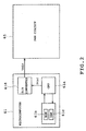
- a portable AC power supply unit 1 comprises an engine drive AC generator 2 and an inverter unit 3 having output terminals 3a and 3b from which a sinusoidal AC voltage is delivered.
- the inverter unit 3 includes a rectifier circuit 4 rectifying a three-phase AC voltage generated by the AC generator 2, a smoothing capacitor 5, a single-phase full-bridge inverter circuit 6, a filter circuit 7, a control circuit 8 and a drive circuit 9.
- the control circuit 8 includes a microcomputer 10 and a pulse-width-modulation (PWM) circuit 11 generating a drive signal.
- the inverter circuit 6 is adapted to be connected to a load. When a plurality of the portable AC power supply units 1 are to be connected to each other, the inverter circuits 6 of the respective power supply units 1 are connected to each other.
- the control circuit 8 controls the generator 2 so that the engine maintains a predetermined number of revolution.
- the control circuit 8 further performs a PWM control so that a sine wave AC voltage having a predetermined voltage (for example, an effective value of 100V) at a predetermined frequency (50Hz or 60Hz) is delivered from the output terminals 3a and 3b.
- the control circuit 8 further includes an output voltage detecting circuit 12 detecting an output voltage of the inverter circuit 6, an output current detecting circuit 13 detecting an output current of the inverter circuit 6 and a phase difference detecting circuit 14 detecting a phase difference between the output voltage and the output current.
- the control circuit 8 increases an output frequency when the output current lags behind the output voltage.
- control circuit 8 decreases the output frequency when the output current leads the output voltage. Consequently, an output balance is achieved between the two AC power supply units 1 connected in parallel with each other.
- the output frequencies are adjusted in a range between 49.90Hz and 50.10Hz when the portable AC power supply units are of 50Hz specification.
- the phase difference is detected by measuring a time from a zero cross point of the output voltage (AC) to a zero cross point of the output current.
- AC output voltage
- the zero crossing may occur twice or the timing of the zero crossing may not be normal.
- the output currents are not balanced between the power supply units in a parallel operation of the power supply units.
- an object of the present invention is to provide an inverter in which the output currents are balanced in the parallel operation of the power supply units.
- the present invention provides an inverter comprising a DC power supply circuit, an inverter circuit having a plurality of switching elements and switching an output of the DC power supply circuit on the basis of a PWM signal to deliver a high-frequency voltage, a filter circuit converting the high-frequency voltage to a substantially sinusoidal AC voltage, characterized by a power detector detecting an effective or wattless power of the AC power, a phase angle calculator calculating a phase angle of current relative to voltage from the detected effective or wattless power, a phase detector detecting a leading or lagging state of the phase angle, and a controller decreasing a frequency of the output voltage when the phase detector detects the leading state of the phase angle, the controller increasing the frequency of the output voltage when the phase detector detects the lagging state of the phase angle.
- the effective power or wattless power contains a phase angle element between the output voltage and the output current.
- the effective or wattless power is detected, and the phase angle calculator calculates a phase angle on the basis of the detected effective or wattless power. Consequently, an accurate phase angle can be detected even when the output current or the output current detector contains a waveform distortion and accordingly, the accuracy in the detection of the phase angle can be improved.
- the phase detector detects the leading or lagging state of the calculated phase angle, and the controller decreases the frequency of the output voltage when the phase detector detects the leading state of the phase angle.
- the phase detector increases the frequency of the output voltage when the phase detector detects the lagging state of the phase angle. Consequently, an accurate frequency control can be carried out, and the output currents are balanced in the parallel operation of the power supply units.
- the inverter of the invention is incorporated in a portable AC power supply unit in the embodiment.
- a portable AC power supply unit 21 generating AC power of 100 V and 50 Hz or 60 Hz, for example.
- the portable AC power supply unit 21 comprises a three-phase AC generator 22 driven by an engine (not shown) and a single-phase inverter unit 23 connected to a rear stage of the generator.
- the generator 22 includes a rotor, an armature neither of which is shown, and a stepping motor 24 controlling a flow rate of fuel (gasoline) to the engine so that a rotational speed of the engine is controlled.
- the armature has Y-connected primary windings 25u, 25v and 25w wound thereon and an auxiliary winding 26 wound thereon.
- Primary winding terminals 27u, 27v and 27w and auxiliary winding terminals 28a and 28b are connected to input terminals 29u, 29v and 29w, 30a and 30b of the inverter unit 23 respectively.
- a rectifier circuit 33 is connected between DC power supply lines 31 and 32.
- the rectifier circuit 33 is further connected to the input terminals 29u, 29v and 29w.
- a smoothing capacitor 34 and an inverter circuit 37 are also connected between the DC power supply lines 31 and 32.
- the inverter circuit 37 is further connected to output terminals 35 and 36 of the inverter unit 23.
- a filter circuit 38 is connected to the inverter circuit 37.
- the rectifier circuit 33 serves as a DC power supply circuit in the invention.
- the rectifier circuit 33 comprises thyristors 39 to 41 and diodes 42 to 44 connected into a three-phase hybrid bridge configuration.
- the inverter circuit 37 comprises transistors (switching elements) 45 to 48 and diodes 49 to 52 connected into a full bridge configuration.
- the filter circuit 38 comprises a reactor 55 and a capacitor 56.
- the reactor 55 is interposed between the output terminal 53 of the inverter circuit 37 and the output terminal 35 of the inverter unit 23.
- the capacitor 56 is connected between the output terminals 35 and 36 of the inverter unit 23.
- the inverter circuit 37 has an output terminal 54 directly connected to the output terminal 36 of the inverter unit 23.
- a current transformer 57 is connected across a current path between the output terminal 54 and the filter circuit 38 for detecting an output current.
- the output terminals 35 and 36 of the inverter units 23 are connected in parallel with each other or one another, respectively.
- the inverter unit 23 further comprises a control power supply circuit 58, a control circuit 59 and a drive circuit 60.
- AC voltage induced in the auxiliary winding 26 is supplied to input terminals 30a and 30b of the control power supply circuit 58.
- the supplied AC voltage is rectified and smoothed into a control DC voltage (5 V or ⁇ 15 V, for example) for energizing the control circuit 59.
- the AC voltage induced in the auxiliary winding 26 is also supplied to the control circuit 59 for detection of the rotational speed of the engine.
- the control circuit 59 comprises a microcomputer 61, a DC voltage detecting circuit 62, an output voltage detecting circuit 63, an output current detecting circuit 64 and a pulse width modulation (PWM) circuit 65.
- PWM pulse width modulation
- the microcomputer 61 comprises a CPU 61a, a ROM 61b and a RAM 61c the latter two of which serve as storage means, and a D/A converter 61d serving as sine wave reference signal generator, as shown in FIG. 2.
- the microcomputer 61 further includes an input/output port, an A/D converter, a timer circuit, an oscillator circuit none of which are shown. These components are incorporated into a one-chip IC.
- the ROM 61b stores as initial data sine wave reference data D(n) for one cycle where n changes from 1 to 256.
- FIG. 3 shows a data table of the sine wave reference data. More specifically, an axis of abscissas denotes a memory address sequence, whereas an axis of ordinates denotes sine wave reference data D(n).
- the sine wave reference data D(n) is sequentially increased or decreased between 1 and 256.
- the RAM 61c stores new sine wave reference data D(n).
- the sine wave reference data D(n) stored on the ROM 61b includes 256 data for one cycle as shown in FIG. 3.
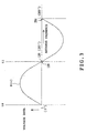
- the 256 data correspond to values of amplitude of a sine wave reference signal Vsin (as shown in FIG. 4).
- the 256 data are sequentially read out by the CPU 61a at an equal time interval for 1/50 sec.
- the power supply frequency is at 60 Hz, the 256 data are sequentially read out by the CPU 61a at an equal time interval for 1/60 sec.
- the DC voltage detecting circuit 62 detects DC voltage Vdc between the DC power supply lines 31 and 32 to deliver the detected DC voltage as a DC voltage signal to the microcomputer 61.
- the microcomputer 61 inputs the DC voltage signal.
- the microcomputer 61 turns off the thyristors 39 to 41 when the input DC voltage Vdc is above 180 V.
- the microcomputer 61 turns on the thyristors 39 to 41 when the input DC voltage Vdc is at or below 180 V.
- the output voltage detecting circuit 63 serving as output current detector includes a voltage divider circuit dividing voltage between the terminals 53 and 54 of the inverter circuit 37 and a filter eliminating carrier wave components from divided rectangular wave voltage, neither of which is shown.
- the output voltage detecting circuit 63 delivers an output voltage signal Vs to the microcomputer 61 and the PWM circuit 65.
- the output current detecting circuit 64 converts the output current detected by the current transformer 57 to a predetermined voltage level.
- the output current detecting circuit 64 delivers an output current signal Is as an output current signal to the microcomputer 61 and the PWM circuit 65.
- the PWM circuit 65 executes a PWM control to generate drive signals G1 to G4 for the transistors 45 to 48 respectively.
- the drive signals G1 to G4 are applied via the drive circuits 60 to the bases of the transistors 45 to 48 respectively.
- An output frequency of the microcomputer 61 is set at either 50 Hz or 60 Hz by an input from an switch input section (not shown).
- the PWM circuit 65 is supplied with the sine wave reference signal Vsin as an AC reference voltage having a frequency equal to the set output frequency.
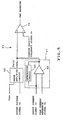
- the sine wave reference signal Vsin is supplied to an error amplifier circuit 66 of the PWM circuit 65 as shown in FIG. 5.
- the error amplifier circuit 66 is also supplied with an output voltage signal Vs delivered by the output voltage detecting circuit 63.
- the error amplifier circuit 63 executes amplification by subtraction to deliver a PWM control signal Vsin', whereupon the output voltage signal Vs is adjusted so that voltage and frequency of the signal Vs correspond to set values respectively, namely, a feedback control is carried out for the output voltage.
- the sine wave reference signal Vsin is also used for calculation of an effective power as will be described later.
- the PWM circuit 65 includes a peak limiter circuit 67 as shown in FIG. 5.
- the peak limiter circuit 67 comprises an operational amplifier 68 and an integration circuit 69.
- the output current signal Is delivered by the output current detecting circuit 64 is supplied to the operational amplifier 68.
- a peak current reference signal Ik is also supplied to the operational amplifier 68.
- the operational amplifier 68 is turned on with respect to a portion where the peak current reference signal Ik is exceeded.
- the aforesaid peak current reference signal Ik includes signal levels of +Ik and -Ik due to hysteresis as shown in FIG. 6A.
- the integration circuit 69 applies feedback to the operational amplifier 68, a peak portion of the PWM control signal Vsin' is cut off substantially into a flat portion as shown in FIG. 6C. Without the integration circuit 69, the PWM control signal Vsin' delivered by the peak limiter circuit 69 would instantaneously rise up and fall down such that the circuit would oscillate. In the embodiment, however, such a problem can be solved since the PWM control signal Vsin' takes a sinusoidal waveform when no overcurrent occurs, as shown by broken line in FIG. 6C.
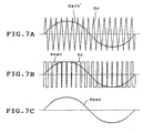
- the PWM circuit 65 includes a comparator 70 comparing the aforesaid PWM control signal Vsin' with a carrier wave frequency signal Sc such as a triangular wave of 16 kHz, for example, as shown in FIG. 7A.
- the carrier wave frequency signal Sc is shown as having an excessively low frequency for the purpose of illustration in the drawing. Consequently, the PWM circuit 65 generates drive signals G1 to G4 so that a triangular wave high-frequency voltage V0 (100 V, 50 or 60 Hz) as shown in FIG. 7B is obtained.
- the filter circuit 38 eliminates high frequency components from the voltage V0 such that AC output V0ac of 100 V, 50 or 60 Hz is produced as shown in FIG. 7C.
- the PWM control signal Vsin' as shown in FIG. 7A denotes the condition where no overcurrent has occurred.
- the microcomputer 61 serves as a power detector, a phase angle detector, a phase detector and a controller. Upon start of operation, the microcomputer 61 controls an output frequency according to the flowchart of FIG. 8. More specifically, at step Q1, the microcomputer 61 detects an initial zero cross in one cycle of the sine-wave reference voltage Vsin (see timing t0 in FIG. 4). Since an effective zero cross of the sine-wave reference signal Vsin corresponds with an effective zero cross of the output voltage V0, timing t0 of the initial zero cross in one cycle of the reference signal Vsin is detected.
- the microcomputer 61 determines which an instantaneous value Is(1) of the current is, positive or negative, namely, whether the current leads or lags behind the voltage, thereby detecting whether a phase angle ⁇ is in the leading or lag phase.
- the microcomputer 61 obtains products of the instantaneous values Is(n) at times (1) to (6) in FIG. 4 and the sine-wave reference signal Vsin(n) which is previously found, storing data of the obtained values.
- the microcomputer 61 further obtains a square of the instantaneous value I(n) at step Q5, storing data of the obtained value (step Q5).
- step Q9 the microcomputer 61 calculates a phase angle ⁇ .
- the microcomputer 61 determines that the phase angle ⁇ is in the leading phase. On the other hand, when the instantaneous value Is(n) is negative at step Q2, the microcomputer 61 determines that the phase angle ⁇ is in the lag phase.
- an output frequency is set on the basis of the phase angle ⁇ and the leading or lag phase.
- This setting is executed on the basis of a data table as shown in FIG. 9. More specifically, when the phase angle is in the leading phase, the output frequency is set so as to become small according to the phase angle ⁇ .
- the output frequency is set so as to become large according to the phase angle ⁇ when the phase angle is in the lag phase. For example, the output frequency is 50.0 Hz when the phase angle ⁇ is 0°.
- the output frequency is 50.1 Hz when the phase angle ⁇ is 90°.
- the output frequency is linearly set between these values.
- the microcomputer 61 has a function of detecting the DC voltage Vdc to adjust the output voltage irrespective of an on-off control of the thyristors 39 to 41. More specifically, as shown in steps R1 to R3 of FIG. 10, when the DC voltage Vdc is at or above 180 V, the output voltage is controlled to be increased. That is, the amplitude of the sine wave reference signal Vsin is increased so that the output voltage is increased. For example, when the DC voltage Vdc rises 1 V from 180 V, the output frequency is increased 0.01 Hz.
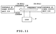
- FIG. 11 Two portable AC power supply units 21A and 21B are shown. Assume now that the output frequency of the unit 21B has instantaneously reduced to 49.96 Hz for some reason (load variation, for example). In this case, a cross current flows from the unit 21A to the unit 21B. In the unit 21B, the current leads the voltage and the phase angle is in the leading phase, whereas the current lags behind the voltage in the unit 21A such that the phase angle is in the lag phase. In the embodiment, the output frequency is increased when the phase angle is in the lag phase, and the output frequency is reduced when the phase angle is in the leading phase.
- the output frequency is increased in the unit 21A, whereas the output frequency is reduced in the unit 21B. Consequently, an amount of cross current flowing into the unit 21A is reduced such that the cross current is resolved between the units 21A and 21B.
- the output frequency since the output frequency is increased or reduced according to the phase angle ⁇ , the output frequency can be controlled promptly so as to take an optimum value.
- the effective power P contains the element of phase angle ⁇ between the output voltage and the output current.
- the effective power P is detected, and the phase angle ⁇ is calculated on the basis of the detected effective power P. Accordingly, an accurate phase angle ⁇ can be detected even when the output current or the signal Is detected by the output current detecting circuit 64 has waveform distortion. Consequently, the accuracy in the detection of the phase angle ⁇ can be improved.
- an appropriate frequency control can be performed on the basis of a phase angle with higher detection accuracy, and the output currents are normally balanced between the power supply units in the case of the parallel operation.
- the effective power is detected in the half cycle of the sine wave reference signal Vsin. Accordingly, the detection of the effective power can be executed in a short period of time and the subsequent frequency control can be carried out quickly. However, the effective power may be detected in one cycle of the sine wave reference signal Vsin, instead.
- FIG. 12 illustrates a case where the output voltage of the unit 21B is higher than the output voltage of the unit 21A although the output frequencies of both units 21A and 21B are the same (50 or 60 Hz).
- a cross current flows from the 21B to the unit 21A.
- the output voltage adjusting function of the unit 21A detects the DC voltage Vdc which is at or above 180 V, thereby increasing the output voltage. As a result, the cross current can be prevented from flowing into the unit 21A.
- FIGS. 13 and 14 show a second embodiment of the invention.
- the second embodiment differs from the first embodiment in that a wattless power is calculated from the effective power so that the output frequency is set according to the leading or lag phase of the phase angle in the wattless power.
- Steps S1 to S8 in the flowchart of FIG. 13 are identical with the steps Q1 to Q8 in FIG. 8 respectively.
- the value of cos ⁇ is obtained at step S9.
- the value of sin ⁇ is obtained from cos ⁇ and the wattless power is calculated (wattless power calculator).
- the leading or lag phase of the phase angle is determined at step S2 (phase detector). The phase angle is in the leading phase when the instantaneous value I(1) of the current is positive.
- the phase angle is in the lag phase when the instantaneous value is negative.
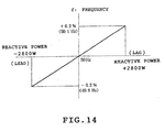
- the frequency is set on the basis of the magnitude of the wattless power and the phase with reference to the data table as shown in FIG. 14. For example, when the wattless power in the leading phase is at -2800 W (corresponding to phase angle ⁇ of -90°), the frequency is set at 49.9 Hz. Consequently, the same effect can be achieved from the second embodiment as from the first embodiment.
- FIGS. 15A to 15C illustrate a third embodiment of the invention.
- the microcomputer 61 sets a signal Vx having a waveform leading the sine wave reference signal Vsin by 90°.
- the product of the signal Vx and the output current signal Is is obtained six times in a half cycle.
- the six products are added together, whereby the wattless power is detected.
- the wattless power can directly be obtained.
- FIGS. 16A to 16D illustrate a fourth embodiment of the invention.
- the portable AC power supply units 21 of the first and second embodiments can cope with a case where a relatively small cross current flows into one of the units in parallel operation.
- the phase angle is not more than 90° and the effective power is positive though the phase angle is in the leading or lag phase, as shown in FIG. 16A.
- the cross current is large, switching elements of the inverter circuit of the unit into which the cross current flow may be damaged. Accordingly, the cross current needs to be resolved or eliminated earlier.
- the current signal Is is 90° or more out of phase with the sine wave reference signal Vsin (180° out of phase) and the effective power is negative.
- an output voltage controller is provided for increasing the output voltage when the detected effective power is negative. Consequently, since a large cross current is prevented from flowing into the power supply unit without detection of the phase angle, phase lead or lag, the switching elements of the inverter circuit or the like can effectively be prevented from being damaged.
- an auxiliary controller may be provided for increasing the frequency of the output voltage when the detected effective power is negative. As a result, since the increase in the frequency reduces an amount of the cross current flowing into the power supply unit, the same effect can be achieved from the fourth embodiment as from the first embodiment.
- FIGS. 17 to 21 illustrate a fifth embodiment of the invention.
- the CPU (not shown) of the microcomputer 61 in the first embodiment further severs as a corrected value calculator, a phase angle detector and a sine wave reference data corrector, so that the sine wave reference signal is corrected to prevent variations in the output voltage.
- the microcomputer 61 delivers the sine wave reference signal Vsin as will be described later.
- the PWM circuit 65 delivers a PWM signal on the basis of the sine wave reference signal Vsin.
- the inverter circuit 37 controls the switching elements 45 to 48 on the basis of the PWM signal thereby to deliver a high-frequency voltage V 0 as shown in FIG. 7.
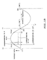
- the output voltage detecting circuit 63 detects output voltage, and the microcomputer 61 determines whether the output current signal Is is in the leading or lag phase at zero cross t 0 and zero cross t 1 of the output voltage Vs, as shown in FIG. 20.
- the microcomputer 61 determines that the output current signal is in the leading phase.
- the microcomputer 61 determines that the output current signal Is is in the lag phase.
- the microcomputer 61 determines that the output current signal Is is in the leading phase.
- the microcomputer 61 determines that the output current signal Is is in the lag phase.
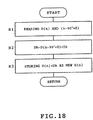
- the microcomputer 61 corrects the sine wave reference data D(n) according to the flowcharts of FIGS. 17 and 18 thereby to correct the sine wave reference signal Vsin. More specifically, the microcomputer 61 sets the parameter n of the sine wave reference data D(n) at 0 at step Q1 in FIG. 17. The microcomputer 61 then increments the parameter n at step Q2 and carries out the correcting control at step Q3. The correcting control is shown as a subroutine in FIG. 18. At step R1, the microcomputer 61 reads from ROM 61b the sine wave reference data D(n) corresponding to the current output timing. In this case, data D(1) and sine wave reference data leading the data D(1) by 90° and displaced by a phase angle ⁇ .
- n is increased to "2,” “3,” “4" and so on for every increase of (360/256)° when n is "1" at the phase angle of 0°.
- the aforesaid (360/256)° becomes (1/50 sec.)/256 at 50 Hz and (1/60 sec.)/256 at 60 Hz.
- Sequence "y” leads sequence "x” by the phase angle ⁇ .
- sequence "y" is out of the range between 1 and 256, the data displaced from sequence "y” by 180° is inverted. See “y'" in FIG. 19.
- the sine wave reference data D(n+90°+ ⁇ ) is the sine wave reference data D(y) in this sequence "y".
- the microcomputer 61 then multiplies the data D(n+90°+ ⁇ ) by a correction value Ih to originate correction data Dh.
- the correction value Ih will be described later.
- the microcomputer 61 then advances to step R3 where the correction data Dh is added to the current sine wave reference data D(n) to obtain new sine wave reference data D(n). Data stored on RAM 61c is renewed such that the new data D(n) is stored on RAM 61c.
- the microcomputer 61 further advances to step Q4 in FIG. 17 to deliver the new data D(n) to the D/A converter 61d.
- An output cycle is set to be at time intervals of 256 for 1/50 sec. in the frequency of 50 Hz and at time intervals of 256 for 1/60 sec. in the frequency of 60 Hz.
- the microcomputer 61 squares the detected current value Id(n), storing data of the squared value. The microcomputer 61 then advances to step Q8 to determine whether n is 128 or 256. Since n is less than 128 at the beginning, the microcomputer 61 determines in the negative (NO) at step Q8, returning to step Q2. Thus, when steps Q2 to Q7 are repeatedly carried out at 128 times or a half cycle is completed, the microcomputer 61 determines in the affirmative at step Q8, advancing to step Q9 where the microcomputer 61 determines whether n is 128. When n is 128, the microcomputer 61 advances to step Q10 to calculate effective power P when n is 1 to 128.
- the microcomputer 61 calculates an effective current value I at step Q11.
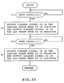
- the result of detection at step S2 in FIG. 21 is the latest.
- the phase angle ⁇ is in the leading phase when the latest result of detection is positive.
- the phase angle 6 is in the lagging phase when the result of detection is negative.
- a correction value Ih is calculated at step Q13.
- the correction value is obtained by multiplying a factor k by an effective value I of current.
- the factor k depends upon the reactor 55 of the filter circuit 38 etc.
- the microcomputer 61 then returns to step Q1.
- the sine wave reference data D(n) for one cycle is supplied to the D/A converter 61d.
- the D/A converter 61d delivers the sine wave reference signal Vsin on the basis of the supplied data D(n).
- the delivered sine wave reference signal Vsin is supplied to the PWM circuit 65.
- the microcomputer 61 reads out the sine wave reference data D(n) corresponding to the current output timing.
- the microcomputer 61 further reads out the sine wave reference data D(y) leading the read data D(n) by 90° and shifted by the phase angle ⁇ relative to the read data D(n).
- the microcomputer 61 multiplies the correction value Ih by the read sine wave reference data D(y) to obtain correction data Dh.
- the microcomputer 61 further adds the correction data Dh to the sine wave reference data D(n) corresponding to the current output timing to obtain new sine wave reference data D(n).
- the corrected sine wave reference data D(n) is delivered to the D/A converter 61d, which delivers the sine wave reference signal corrected on the basis of the corrected sine wave reference data D(n). Consequently, the variations in the output voltage can be reduced. Further, the above-described arrangement requires no analog circuit such as a differential amplifier including resistors and capacitors or a power factor correcting circuit including resistors, capacitors and an operational amplifier. Consequently, the circuit arrangement can be simplified and accordingly, the cost can be reduced.
- the current value Id is detected in the half cycle of the output voltage signal Vs corresponding to the half cycle of the output voltage, and the effective current value I is calculated. Consequently, the output current value can be detected in a short period of time, and the detected effective value I contains a reduced amount of error detection.
- the current value Id may be detected in one cycle of the output voltage signal Vs, instead.
- the effective power P is calculated on the basis of the sine wave reference data D(n) in the half cycle and the effective value I, and the phase angle ⁇ is calculated on the basis of the effective power P in the half cycle. Consequently, the phase angle can be detected in a short period of time.
- the effective power P may be calculated on the basis of the data D(n) detected in one cycle.
- each of calculation of the correction value Ih and detection of the phase angle ⁇ may be carried out in a half cycle of the output voltage signal Vs.
- the obtained correction value Ih and phase angle ⁇ are used for correction of the data D(n) and output of the signal Vsin in the next half cycle. Consequently, the control for correction of the sine wave reference signal Vsin can be performed quickly such that a quick feedback control can be realized.
- the sine wave reference data D(n) corresponding to 256 phase angles in one cycle of the AC voltage to be delivered are stored in the foregoing embodiments.
- the number of data should not be limited to 256.
- the data in a half cycle of the AC voltage may be stored, instead. In this case, since the polarity in a first half cycle is inverted in the next half cycle, the data used in the first half cycle needs to be inverted in the next half cycle.
Applications Claiming Priority (4)
| Application Number | Priority Date | Filing Date | Title |
|---|---|---|---|
| JP2000262832 | 2000-08-31 | ||
| JP2000262832A JP4693214B2 (ja) | 2000-08-31 | 2000-08-31 | インバータ装置 |
| JP2001001497 | 2001-01-09 | ||
| JP2001001497A JP4672149B2 (ja) | 2001-01-09 | 2001-01-09 | インバータ装置 |
Publications (2)
| Publication Number | Publication Date |
|---|---|
| EP1187305A2 true EP1187305A2 (de) | 2002-03-13 |
| EP1187305A3 EP1187305A3 (de) | 2006-06-07 |
Family
ID=26598924
Family Applications (1)
| Application Number | Title | Priority Date | Filing Date |
|---|---|---|---|
| EP01307387A Withdrawn EP1187305A3 (de) | 2000-08-31 | 2001-08-30 | Zum Gebrauch mit einer tragbaren Wechselstromversorgungseinheit geeigneter Wechselrichter |
Country Status (2)
| Country | Link |
|---|---|
| US (2) | US20020024828A1 (de) |
| EP (1) | EP1187305A3 (de) |
Cited By (6)
| Publication number | Priority date | Publication date | Assignee | Title |
|---|---|---|---|---|
| WO2008077525A2 (de) * | 2006-12-21 | 2008-07-03 | Prettl, Rolf | Wandlerschaltkreis zur wechselumrichtung elektrischer leistungsgrössen, verfahren zum ansteuern eines wandlerschaltkreises und stromerzeuger |
| RU2549917C2 (ru) * | 2013-10-04 | 2015-05-10 | Федеральное государственное бюджетное образовательное учреждение высшего профессионального образования "Чувашский государственный университет имени И.Н. Ульянова" | Устройство ультразвуковой очистки отложений в теплообменных аппаратах |
| EP2063194B1 (de) * | 2007-11-20 | 2015-11-11 | LG Electronics Inc. | Motorsteuerung einer Klimaanlage |
| EP2478606A4 (de) * | 2009-09-18 | 2017-01-18 | Queen's University At Kingston | Schnittstelle für verteilte energieerzeugung |
| EP3343745A1 (de) * | 2016-12-29 | 2018-07-04 | MICROTEC S.r.l. | Wechselrichter-generator-vorrichtung |
| CN110048584A (zh) * | 2018-01-12 | 2019-07-23 | Abb瑞士股份有限公司 | 确定及补偿功率晶体管延迟 |
Families Citing this family (55)
| Publication number | Priority date | Publication date | Assignee | Title |
|---|---|---|---|---|
| DE60305363T2 (de) * | 2002-03-15 | 2007-03-29 | Japan Servo Co. Ltd. | Schrittmotorantrieb |
| US7042110B2 (en) * | 2003-05-07 | 2006-05-09 | Clipper Windpower Technology, Inc. | Variable speed distributed drive train wind turbine system |
| US6989650B2 (en) * | 2003-09-11 | 2006-01-24 | Oilfield-Electric-Marine, Inc. | AC motor control system using parallel integrated sub systems |
| US7733676B2 (en) * | 2004-03-30 | 2010-06-08 | Daifuku Co., Ltd. | Non-contact power supply system utilizing synchronized command signals to control and correct phase differences amongst power supply units |
| KR100636749B1 (ko) * | 2004-10-15 | 2006-10-19 | 주식회사 현대오토넷 | 차량 교류전원 공급장치 |
| JP2006217780A (ja) * | 2005-02-07 | 2006-08-17 | Yamaha Motor Co Ltd | インバータ式交流発電装置 |
| FR2888686B1 (fr) * | 2005-07-18 | 2007-09-07 | Schneider Toshiba Inverter | Dispositif d'alimentation d'un variateur de vitesse |
| DE102005042615A1 (de) * | 2005-09-07 | 2007-03-08 | Franz Haimer Maschinenbau Kg | Schaltung, Schrumpfbefestigung und Verfahren zur Regelung |
| US7626836B2 (en) * | 2005-10-26 | 2009-12-01 | Rockwell Automation Technologies, Inc. | Method and apparatus for adjustable voltage/adjustable frequency inverter control |
| DE102006050077A1 (de) * | 2006-10-24 | 2008-05-08 | Repower Systems Ag | Umrichter mit steuerbarem Phasenwinkel |
| US7852643B2 (en) * | 2007-06-27 | 2010-12-14 | General Electric Company | Cross current control for power converter system |
| US7847433B2 (en) * | 2007-11-27 | 2010-12-07 | Rain Bird Corporation | Universal irrigation controller power supply |
| DE102008012859B4 (de) | 2007-12-21 | 2023-10-05 | OSRAM Opto Semiconductors Gesellschaft mit beschränkter Haftung | Laserlichtquelle mit einer Filterstruktur |
| KR101461559B1 (ko) * | 2007-12-21 | 2014-11-13 | 엘지전자 주식회사 | 공기조화기의 전동기 제어장치 |
| US8625315B2 (en) * | 2008-05-09 | 2014-01-07 | Etm Electromatic Inc | Inverter modulator with variable switching frequency |
| PE20110472A1 (es) * | 2008-06-27 | 2011-07-01 | Univ California | Circuito para extraccion de energia directa a partir de una haz de particula con carga |
| US8330430B2 (en) * | 2008-11-14 | 2012-12-11 | Remy Technologies, Llc | Alternator regulator with variable rotor field frequency |
| TWI382639B (zh) * | 2009-04-24 | 2013-01-11 | Well Shin Technology Co Ltd | 車用直流電壓轉換器 |
| US8493014B2 (en) * | 2009-08-10 | 2013-07-23 | Emerson Climate Technologies, Inc. | Controller and method for estimating, managing, and diagnosing motor parameters |
| US8358098B2 (en) * | 2009-08-10 | 2013-01-22 | Emerson Climate Technologies, Inc. | System and method for power factor correction |
| US8406021B2 (en) * | 2009-08-10 | 2013-03-26 | Emerson Climate Technologies, Inc. | System and method for reducing line current distortion |
| US8476873B2 (en) * | 2009-08-10 | 2013-07-02 | Emerson Climate Technologies, Inc. | System and method for current balancing |
| US8264192B2 (en) | 2009-08-10 | 2012-09-11 | Emerson Climate Technologies, Inc. | Controller and method for transitioning between control angles |
| US8508166B2 (en) | 2009-08-10 | 2013-08-13 | Emerson Climate Technologies, Inc. | Power factor correction with variable bus voltage |
| US8344706B2 (en) * | 2009-08-10 | 2013-01-01 | Emerson Climate Technologies, Inc. | System and method for rejecting DC current in power factor correction systems |
| US8264860B2 (en) * | 2009-08-10 | 2012-09-11 | Emerson Climate Technologies, Inc. | System and method for power factor correction frequency tracking and reference generation |
| US8698433B2 (en) | 2009-08-10 | 2014-04-15 | Emerson Climate Technologies, Inc. | Controller and method for minimizing phase advance current |
| WO2011029480A1 (en) * | 2009-09-11 | 2011-03-17 | Abb Research Ltd | Fault current limitation in dc power transmission systems |
| JP5491207B2 (ja) * | 2010-01-13 | 2014-05-14 | キヤノン株式会社 | ステッピングモータの駆動装置 |
| CN101895204B (zh) * | 2010-06-03 | 2012-05-23 | 山东新风光电子科技发展有限公司 | 高压变频器电路结构 |
| WO2012014292A1 (ja) * | 2010-07-28 | 2012-02-02 | 三菱電機株式会社 | チョッパ装置 |
| JP2012078782A (ja) * | 2010-09-09 | 2012-04-19 | Ricoh Co Ltd | 高電圧電源装置、画像形成装置、及びカラー画像形成装置 |
| US9197068B2 (en) * | 2010-09-30 | 2015-11-24 | Abb Research Ltd. | Coordinated control of multi-terminal HVDC systems |
| CN102162428B (zh) * | 2011-02-23 | 2013-12-04 | 深圳市华为安捷信电气有限公司 | 控制器、控制能源的方法和侦测控制信号板 |
| US8902616B2 (en) * | 2011-10-13 | 2014-12-02 | Rockwell Automation Technologies, Inc. | Active front end power converter with diagnostic and failure prevention using peak detector with decay |
| US9634593B2 (en) | 2012-04-26 | 2017-04-25 | Emerson Climate Technologies, Inc. | System and method for permanent magnet motor control |
| CN202634345U (zh) * | 2012-05-04 | 2012-12-26 | 中山大洋电机股份有限公司 | 一种可适应不同频率不同供电电压的ecm电机控制器 |
| WO2014026124A1 (en) | 2012-08-10 | 2014-02-13 | Emerson Climate Technologies, Inc. | Motor drive control using pulse-width modulation pulse skipping |
| US9557753B2 (en) * | 2012-10-10 | 2017-01-31 | Maschinefabrik Reinhausen Gmbh | Method for regulating the voltage of a transformer |
| US9939883B2 (en) | 2012-12-27 | 2018-04-10 | Nvidia Corporation | Supply-voltage control for device power management |
| CN203278615U (zh) * | 2013-05-22 | 2013-11-06 | Abb技术有限公司 | 一种用于中高压变频器的功率模块及包含其的变频器 |
| US9602083B2 (en) | 2013-07-03 | 2017-03-21 | Nvidia Corporation | Clock generation circuit that tracks critical path across process, voltage and temperature variation |
| US9766649B2 (en) | 2013-07-22 | 2017-09-19 | Nvidia Corporation | Closed loop dynamic voltage and frequency scaling |
| US10466763B2 (en) * | 2013-12-02 | 2019-11-05 | Nvidia Corporation | Dynamic voltage-frequency scaling to limit power transients |
| CN103701334B (zh) * | 2013-12-31 | 2017-03-01 | 重庆力华科技有限责任公司 | 一种内燃机驱动的逆变发电装置及其逆变控制方法 |
| EP3262750B1 (de) | 2015-02-25 | 2020-01-29 | Otis Elevator Company | Zwischeninduktoranordnung für mehrere antriebe in paralleler anordnung |
| CN105610309B (zh) * | 2015-11-18 | 2019-01-18 | 哈尔滨工业大学(威海) | 一种使用直流侧电流直接注入法的大功率整流器 |
| CN107046370B (zh) * | 2016-02-09 | 2020-05-26 | 松下知识产权经营株式会社 | 变换器、电力传输系统及控制器 |
| CN107046379B (zh) * | 2016-02-09 | 2020-07-10 | 松下知识产权经营株式会社 | 变换器、电力传输系统及控制器 |
| CN110603706A (zh) * | 2017-04-07 | 2019-12-20 | 明矾能源私人有限公司 | 多单元建筑物中太阳能受控分配的电表后端系统和方法 |
| CN107086563B (zh) * | 2017-06-15 | 2019-08-23 | 温州大学 | 一种并联供电系统输出功率高效均衡控制方法 |
| CN109981013A (zh) * | 2017-12-27 | 2019-07-05 | 上海大郡动力控制技术有限公司 | 电机相电流采样延迟时间的辨识方法 |
| CN110676840A (zh) * | 2019-08-30 | 2020-01-10 | 合肥学院 | 一种电力系统控制设备和电力系统控制方法 |
| CN112104252B (zh) * | 2020-09-08 | 2021-08-20 | 中车青岛四方车辆研究所有限公司 | 一种动车组辅助变流器功率计算方法和装置 |
| US11533013B1 (en) * | 2021-07-29 | 2022-12-20 | Rivian Ip Holdings, Llc | Pulse width modulation clock synchronization |
Citations (5)
| Publication number | Priority date | Publication date | Assignee | Title |
|---|---|---|---|---|
| US3675037A (en) * | 1971-06-01 | 1972-07-04 | Bell Telephone Labor Inc | Technique for synchronous parallel operation of static inverters |
| US3864620A (en) * | 1973-09-11 | 1975-02-04 | Westinghouse Electric Corp | Arrangement of parallel static ac power sources proportions |
| US4677535A (en) * | 1985-04-30 | 1987-06-30 | Mitsubishi Denki Kabushiki Kaisha | Power conversion system |
| US4947310A (en) * | 1988-05-30 | 1990-08-07 | Mitsubishi Denki Kabushiki Kaisha | Parallel operating system for alternate current output converters |
| US5426578A (en) * | 1992-02-10 | 1995-06-20 | Honda Giken Kabushiki Kaisha | Generator having automatic parallel operation function |
Family Cites Families (11)
| Publication number | Priority date | Publication date | Assignee | Title |
|---|---|---|---|---|
| US3922594A (en) * | 1974-10-15 | 1975-11-25 | Lorain Prod Corp | Control system for phase displacement regulator circuits |
| US4251736A (en) * | 1979-07-23 | 1981-02-17 | United Technologies Corporation | Method for controlling power flow between an electrochemical cell and a power grid |
| JPS60249824A (ja) * | 1984-05-24 | 1985-12-10 | 株式会社東芝 | 交直変換装置の制御方法 |
| US4879639A (en) * | 1987-05-11 | 1989-11-07 | Fuji Electric Co., Ltd. | Power converter for driving an AC motor at a variable speed |
| US5053939A (en) * | 1990-08-27 | 1991-10-01 | Sundstrand Corporation | Control of PWM inverters by pattern development from stored constants relating D.C. link harmonics to output distortion |
| US5083039B1 (en) * | 1991-02-01 | 1999-11-16 | Zond Energy Systems Inc | Variable speed wind turbine |
| JP3192498B2 (ja) | 1991-11-07 | 2001-07-30 | 本田技研工業株式会社 | インバータ装置 |
| US5187427A (en) * | 1991-11-27 | 1993-02-16 | U.S. Windpower, Inc. | Static reactive power compensator |
| JP3356795B2 (ja) | 1992-02-24 | 2002-12-16 | 本田技研工業株式会社 | 発電機 |
| JPH06175741A (ja) * | 1992-12-07 | 1994-06-24 | Mitsubishi Electric Corp | 静止形無効電力発生装置 |
| JP4037080B2 (ja) * | 2001-10-18 | 2008-01-23 | 東芝三菱電機産業システム株式会社 | 電力変換装置の制御回路 |
-
2001
- 2001-08-27 US US09/938,856 patent/US20020024828A1/en not_active Abandoned
- 2001-08-30 EP EP01307387A patent/EP1187305A3/de not_active Withdrawn
-
2003
- 2003-06-10 US US10/457,722 patent/US6771522B2/en not_active Expired - Fee Related
Patent Citations (5)
| Publication number | Priority date | Publication date | Assignee | Title |
|---|---|---|---|---|
| US3675037A (en) * | 1971-06-01 | 1972-07-04 | Bell Telephone Labor Inc | Technique for synchronous parallel operation of static inverters |
| US3864620A (en) * | 1973-09-11 | 1975-02-04 | Westinghouse Electric Corp | Arrangement of parallel static ac power sources proportions |
| US4677535A (en) * | 1985-04-30 | 1987-06-30 | Mitsubishi Denki Kabushiki Kaisha | Power conversion system |
| US4947310A (en) * | 1988-05-30 | 1990-08-07 | Mitsubishi Denki Kabushiki Kaisha | Parallel operating system for alternate current output converters |
| US5426578A (en) * | 1992-02-10 | 1995-06-20 | Honda Giken Kabushiki Kaisha | Generator having automatic parallel operation function |
Cited By (10)
| Publication number | Priority date | Publication date | Assignee | Title |
|---|---|---|---|---|
| WO2008077525A2 (de) * | 2006-12-21 | 2008-07-03 | Prettl, Rolf | Wandlerschaltkreis zur wechselumrichtung elektrischer leistungsgrössen, verfahren zum ansteuern eines wandlerschaltkreises und stromerzeuger |
| WO2008077525A3 (de) * | 2006-12-21 | 2008-09-12 | Prettl Rolf | Wandlerschaltkreis zur wechselumrichtung elektrischer leistungsgrössen, verfahren zum ansteuern eines wandlerschaltkreises und stromerzeuger |
| EP2063194B1 (de) * | 2007-11-20 | 2015-11-11 | LG Electronics Inc. | Motorsteuerung einer Klimaanlage |
| EP2478606A4 (de) * | 2009-09-18 | 2017-01-18 | Queen's University At Kingston | Schnittstelle für verteilte energieerzeugung |
| US9680364B2 (en) | 2009-09-18 | 2017-06-13 | Sparq Systems Inc. | Distributed power generation interface |
| RU2549917C2 (ru) * | 2013-10-04 | 2015-05-10 | Федеральное государственное бюджетное образовательное учреждение высшего профессионального образования "Чувашский государственный университет имени И.Н. Ульянова" | Устройство ультразвуковой очистки отложений в теплообменных аппаратах |
| EP3343745A1 (de) * | 2016-12-29 | 2018-07-04 | MICROTEC S.r.l. | Wechselrichter-generator-vorrichtung |
| CN110048584A (zh) * | 2018-01-12 | 2019-07-23 | Abb瑞士股份有限公司 | 确定及补偿功率晶体管延迟 |
| CN110048584B (zh) * | 2018-01-12 | 2021-04-13 | Abb瑞士股份有限公司 | 确定及补偿功率晶体管延迟 |
| US10985751B2 (en) | 2018-01-12 | 2021-04-20 | Abb Schweiz Ag | Determining and compensating power transistor delay in parallel half bridge legs |
Also Published As
| Publication number | Publication date |
|---|---|
| US20020024828A1 (en) | 2002-02-28 |
| US20030198065A1 (en) | 2003-10-23 |
| EP1187305A3 (de) | 2006-06-07 |
| US6771522B2 (en) | 2004-08-03 |
Similar Documents
| Publication | Publication Date | Title |
|---|---|---|
| EP1187305A2 (de) | Zum Gebrauch mit einer tragbaren Wechselstromversorgungseinheit geeigneter Wechselrichter | |
| US6958589B2 (en) | Inverter controller for driving motor and air conditioner using inverter controller | |
| JP3579841B2 (ja) | 洗濯機モータの速度制御方法及びその装置 | |
| US4066938A (en) | Input current modulation to reduce torque pulsations in controlled current inverter drives | |
| JP2002034160A (ja) | インバータ並列運転装置 | |
| JPS6042717B2 (ja) | 誘導電動機用電力制御装置 | |
| US11196290B2 (en) | Uninterruptible power supply apparatus | |
| US20030067793A1 (en) | Pulse with modualtion inverter generation using a correction co-efficient and a reference to the ratio to obtain a real duty ratio | |
| JP4712148B2 (ja) | 電力変換装置 | |
| EP0769221B1 (de) | Lastkommutierter synchroner motorantrieb | |
| JP4693214B2 (ja) | インバータ装置 | |
| JP3283134B2 (ja) | Pwmコンバータ装置 | |
| GB2114780A (en) | Current control pulse width modulated inverter machine drive system | |
| JP3598936B2 (ja) | インバータ発電装置 | |
| JP4672149B2 (ja) | インバータ装置 | |
| JPH07146724A (ja) | 系統連系型インバータ | |
| JP3992652B2 (ja) | 3相入力充電装置 | |
| JPH0219718B2 (de) | ||
| JP3070314B2 (ja) | インバータの出力電圧補償回路 | |
| JP3371522B2 (ja) | Pwm制御電圧形インバータ | |
| JP3374827B2 (ja) | 無効電力発生装置 | |
| JP3227009B2 (ja) | 交流電気車の制御装置 | |
| JPH10164845A (ja) | Pwm式順変換装置 | |
| JP2827986B2 (ja) | 誘導電動機の制御方法及び装置 | |
| JPH0652998B2 (ja) | 交流電動機給電用3相インバ−タの制御電圧を制御する方法及び装置 |
Legal Events
| Date | Code | Title | Description |
|---|---|---|---|
| PUAI | Public reference made under article 153(3) epc to a published international application that has entered the european phase |
Free format text: ORIGINAL CODE: 0009012 |
|
| 17P | Request for examination filed |
Effective date: 20010919 |
|
| AK | Designated contracting states |
Kind code of ref document: A2 Designated state(s): AT BE CH CY DE DK ES FI FR GB GR IE IT LI LU MC NL PT SE TR |
|
| AX | Request for extension of the european patent |
Free format text: AL;LT;LV;MK;RO;SI |
|
| RIC1 | Information provided on ipc code assigned before grant |
Ipc: H02M 7/48 20060101ALI20060123BHEP Ipc: H02M 7/5387 20060101ALI20060123BHEP Ipc: H02M 5/458 20060101AFI20011211BHEP |
|
| PUAL | Search report despatched |
Free format text: ORIGINAL CODE: 0009013 |
|
| AK | Designated contracting states |
Kind code of ref document: A3 Designated state(s): AT BE CH CY DE DK ES FI FR GB GR IE IT LI LU MC NL PT SE TR |
|
| AX | Request for extension of the european patent |
Extension state: AL LT LV MK RO SI |
|
| AKX | Designation fees paid |
Designated state(s): DE FR GB |
|
| 17Q | First examination report despatched |
Effective date: 20080616 |
|
| STAA | Information on the status of an ep patent application or granted ep patent |
Free format text: STATUS: THE APPLICATION IS DEEMED TO BE WITHDRAWN |
|
| 18D | Application deemed to be withdrawn |
Effective date: 20150303 |