EP1187162A2 - Verfahren zur Herstellung einer Leuchtstofflampe - Google Patents
Verfahren zur Herstellung einer Leuchtstofflampe Download PDFInfo
- Publication number
- EP1187162A2 EP1187162A2 EP01121090A EP01121090A EP1187162A2 EP 1187162 A2 EP1187162 A2 EP 1187162A2 EP 01121090 A EP01121090 A EP 01121090A EP 01121090 A EP01121090 A EP 01121090A EP 1187162 A2 EP1187162 A2 EP 1187162A2
- Authority
- EP
- European Patent Office
- Prior art keywords
- fluorescent lamp
- manufacturing
- lamp according
- glass tubes
- tapping
- Prior art date
- Legal status (The legal status is an assumption and is not a legal conclusion. Google has not performed a legal analysis and makes no representation as to the accuracy of the status listed.)
- Granted
Links
Images


Classifications
-
- H—ELECTRICITY
- H01—ELECTRIC ELEMENTS
- H01J—ELECTRIC DISCHARGE TUBES OR DISCHARGE LAMPS
- H01J9/00—Apparatus or processes specially adapted for the manufacture, installation, removal, maintenance of electric discharge tubes, discharge lamps, or parts thereof; Recovery of material from discharge tubes or lamps
- H01J9/40—Closing vessels
-
- H—ELECTRICITY
- H01—ELECTRIC ELEMENTS
- H01J—ELECTRIC DISCHARGE TUBES OR DISCHARGE LAMPS
- H01J9/00—Apparatus or processes specially adapted for the manufacture, installation, removal, maintenance of electric discharge tubes, discharge lamps, or parts thereof; Recovery of material from discharge tubes or lamps
- H01J9/24—Manufacture or joining of vessels, leading-in conductors or bases
- H01J9/245—Manufacture or joining of vessels, leading-in conductors or bases specially adapted for gas discharge tubes or lamps
-
- H—ELECTRICITY
- H01—ELECTRIC ELEMENTS
- H01J—ELECTRIC DISCHARGE TUBES OR DISCHARGE LAMPS
- H01J9/00—Apparatus or processes specially adapted for the manufacture, installation, removal, maintenance of electric discharge tubes, discharge lamps, or parts thereof; Recovery of material from discharge tubes or lamps
- H01J9/24—Manufacture or joining of vessels, leading-in conductors or bases
- H01J9/26—Sealing together parts of vessels
- H01J9/265—Sealing together parts of vessels specially adapted for gas-discharge tubes or lamps
Definitions
- the present invention relates to a method for manufacturing a fluorescent lamp having an interconnected portion in the glass tubes.
- a fluorescent lamp with a prolonged discharge path which is achieved by interconnecting glass tubes
- a fluorescent lamp with a prolonged discharge path which is achieved by interconnecting glass tubes
- One means for interconnecting glass tubes as described above is, for example, as shown in JP63(1988)-107830A, to heat and melt interconnecting portions of parallel arranged glass tubes respectively from inside the glass tubes by burners, to interconnect the glass tubes through a communicating aperture formed by the wind pressure of the burners, to pinch and close the tube end portions, and then to reheat the tube end portions and put them into a predetermined mold for forming the tube ends into a predetermined shape.
- the present invention solves the conventional problems described above in such a manner that the aperture of the interconnected portion of the glass tubes is formed with a diameter that does not interfere with the performance of the fluorescent lamp and also that breakage of the interconnected portion is prevented during each manufacturing process or after the fluorescent lamp is completed.
- a thickness of the glass tube is in a range of 0.75 mm to 1.50 mm.
- a heating temperature for the interconnecting portions is in a range of 900°C to 1400°C.
- the hammer has an elliptical tip with a minor axis of 3 mm to 7 mm and a major axis of 4 mm to 12 mm.
- a pressure of the preliminary tapping is in a range of 1.1 MPa to 2.2 MPa.
- a pressure of the preliminary tapping and a pressure of thrusting the glass tubes against each other may be approximately the same.
- a pressure of the main tapping is in a range of 1.1 MPa to 2.2 MPa, more preferably 1.8 MPa to 2.2 MPa.
- a pressure of the main tapping may be larger than a pressure of the preliminary tapping.
- an aperture of the interconnected portion has an elliptical shape with a minor axis of 3 mm to 10 mm and a major axis of 4 mm to 15 mm, more preferably with a minor axis of 3 mm to 7 mm and a major axis of 4 mm to 12 mm.
- a heating temperature in the vicinity of the interconnected portion is in a range of 900°C to 1400°C.
- the molding is conducted at a temperature of 930°C to 1200°C, more preferably 930°C to 1030°C.
- a space between the glass tubes is not less than the thickness of the glass tube.
- the preliminary tapping is conducted once or twice, and the main tapping is conducted for two or more times by the hammers.
- the glass tubes are at least partially uncoated by phosphor before the interconnected portion is formed.
- cooling zones can be provided in portions where the glass tubes are molded.
- the glass tubes may be linear or nonlinear glass tubes.
- a phosphor coating is formed partially or entirely on an inner surface of the glass tube after the process of forming the interconnected portion or molding.
- a thickness of the phosphor coating is in a range of 20 ⁇ m to 30 ⁇ m.
- the interconnected portion of the glass tubes can be formed by the steps of heating the interconnecting portions of glass tubes respectively from inside and softening them approximately to the melting point, lightly contacting the glass tubes against each other and thrusting and thinning them by conducting the preliminary tapping once or twice by the hammers, conducting the main tapping repeatedly for two or more times, and forming the apertures with a large diameter by partially ripping off the glass walls so as to avoid the glass walls having an uneven thickness. Therefore, a distortion occurring in the interconnected portion can be prevented.
- the open end portions of the glass tubes near the interconnected portion are heated, melted and closed locally after the interconnection is completed, and then, the glass tubes are molded in the softened state to shape the end portions by using a mold of a predetermined shape.
- the steps from the formation of the interconnected portion to the molding of the end portions of the glass tubes can be conducted continuously, so that the production efficiency can be improved.
- the conditions for the interconnecting process and the molding process also are simple, and the problems such as unevenness and variance in the thickness, unevenness in the shape, and reduction of the glass strength can be solved.
- FIG. 1 is a cross-sectional view showing the relevant portion of a fluorescent lamp in the first step according to a method for manufacturing a fluorescent lamp of the present invention.
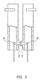
- FIG. 2 is a cross-sectional view showing the relevant portion of a fluorescent lamp in the second step according to a method for manufacturing a fluorescent lamp of the present invention.
- FIG. 3 is a cross-sectional view showing the relevant portion of a fluorescent lamp in the third step according to a method for manufacturing a fluorescent lamp of the present invention.
- FIG. 4 is a cross-sectional view showing the relevant portion of a glass tube manufactured by a method for manufacturing a fluorescent lamp of the present invention.
- FIG. 5 is a diagram showing the tip of a small hammer from the side of the glass tube.
- FIGS. 1 to 4 are cross-sectional views showing the relevant portions of fluorescent lamps according to one example of a method for manufacturing a fluorescent lamp of the present invention.
- 1, 1' denote glass tubes made of a soda glass or the like; 2, 2' denote interconnecting portions; 3, 3' denote gas burners; 4, 4' denote small hammers made of a heat resisting material; 5, 5' denote open end portions of the glass tubes 1, 1'; 6 denotes interconnected portions; 7, 7' denote closed portions; 8, 8' denote cooling zones; and 9 denotes a glass tube completed with the process of interconnection and molding.
- 10 is a holding arm for the glass tube.
- the glass tubes 1, 1' are held by the holding arms 10 and arranged adjacent and parallel to each other at a spacing of not less than a thickness of the glass tubes 1 and 1'.
- the interconnecting portions 2, 2' are heated and softened from the inside by the burners 3, 3' as shown in FIGS. 1, 2 and welded together.
- a preliminary tapping is conducted once or twice by the small hammers 4, 4' to thrust the glass tubes against each other and to thin them.
- a main tapping is conducted twice or several times to open the welding portion, so that the interconnected portion 6 as shown in FIG. 3 is formed.
- the preliminary tapping by the small hammers 4, 4' and the thrusting of the glass tubes against each other may be conducted with almost the same pressure, and the main tapping may be conducted with a slightly higher pressure than that of the preliminary tapping.
- FIG. 5 is a diagram showing the tip of a small hammer from the side of the glass tube.
- the small hammer has an elliptical tip formed with a minor axis of 3 mm to 7 mm and a major axis of 4 mm to 12 mm.
- the open end portions 5, 5' in the vicinity thereof are heated and softened so as to close the end portions and to mold them into a predetermined shape.
- the glass tube 9 shown in FIG. 4 is completed.
- the cooling zones 8, 8' for controlling mercury vapor pressure are formed as necessary due to the type of the fluorescent lamp by using a mold.
- a coating for the inner surface of the glass tube such as a phosphor coating or a conductive coating preferably is formed after the glass tube 9 is completed, but this is not the case if this process is difficult to conduct after forming the glass tube 9.
- a fluorescent lamp (a) which is formed in accordance with the embodiment of the present invention shown in FIGS. 1 to 4
- a fluorescent lamp (b) which is formed by using glass tubes coated in advance with a phosphor coating and forming an interconnected portion by blowing and opening the interconnecting portions by the wind pressure of a burner, were produced experimentally, and various comparative evaluations were conducted.
- the two glass tubes without a phosphor coating were arranged and held parallel to each other at an interval of 1.5 mm, and interconnecting portions were heated and softened respectively at a temperature of 1350°C from inside the glass tubes by burners and welded together. Then, a preliminary tapping was conducted twice with small hammers with 1.5 MPa of pressure to thrust the glass tubes against each other and to thin them. After a while, a main tapping was conducted with 2.2 MPa of pressure continuously for three times to open the welding portion. Then, any excess glass was eliminated to form an interconnected portion.
- the end portions of the glass tubes in the vicinity of the interconnected portion were heated and softened at a temperature of 980°C to close the open ends, and then, the end portions of the glass tubes in the softened state were fit into a mold having dents on both sides and molded at a temperature of 950°C.
- the glass tube 9 having the cooling zones 8, 8' as shown in FIG. 4 was formed.
- a predetermined amount of a three wavelength region light-emitting phosphor of 5000K correlated color temperature made of a composition of Y 2 O 3 : Eu 3+ , LaPO 4 : Ce 3+ , Tb 3+ and BaMgAl 10 O 17 : Eu 2+ was coated on the inner walls of the glass tubes described above.
- the thickness of the applied and dried phosphor coating was 23 ⁇ m.
- This fluorescent lamp (a) was formed such that the cross section of the interconnected portion had an elliptical cross section with a major axis of about 15 mm, and the cooling zones in the end portions of the glass tubes also had a depth of about 15 mm.
- the cross-sectional area of the aperture of the interconnected portion was larger and more uniform in the fluorescent lamp (a), compared to the fluorescent lamp (b). Furthermore, the thicknesses on the upper and lower sides of the interconnected portion were almost the same without any cluster, and no residual distortion was observed.
- the interconnected portion was formed by blowing and opening the glass tubes with sharp flames of the gas burner, so that the diameter as well as the cross-sectional area of the aperture were smaller than those of the fluorescent lamp (a).
- the shape of the aperture also was uneven and variable, and the thicknesses on the upper and lower sides of the interconnected portion were different, so that there was thickness deviation. There were also those in which a residual distortion was detected.
- the fluorescent lamp (b) was coated in advance with a phosphor coating on the inner surface of the glass tube, phosphor particles were present in a state mixed with the glass components in the interconnected portion and in the closed end portions of the tubes, so that there were also those which were distorted.
- the spacing between the glass tubes is larger than the thickness of these glass tubes, the periphery of the interconnected portion including the upper and lower sides of the interconnected portion is less likely to form a cluster, and the glass tubes can be thinned more easily by the preliminary tapping with the hammers. Thus, the time required for opening can be shortened.
- the portion thinned by the preliminary tapping could be opened in an instant by the first main tapping, and the remaining glass in the periphery of the aperture was ripped off by the second or further main tapping.
- the shape of the aperture could be formed uniformly with a stable size.
- the method for manufacturing a fluorescent lamp of the present invention can realize the steps from the formation of an interconnected portion of glass tubes to the molding of tube ends in a smooth sequence, so that a fluorescent lamp having a uniform and strong interconnected portion and also without distortion can be formed.
- the glass tubes may be linear or nonlinear glass tubes, and the present invention is not limited to the material, the size, and the type explained in the embodiment, the drawings, and the example of the present invention, and can be applied to a method for manufacturing a fluorescent lamp in a broad range.
- the method for manufacturing a fluorescent lamp of the present invention can be applied surely, for example, to a production of fluorescent lamps or the like, which are formed by interconnecting a plurality of interconnected glass tubes, and if necessary, also to an interconnection of glass tubes coated with phosphor coatings on the inner surface.
- the method for manufacturing a fluorescent lamp of the present invention comprises heating interconnecting portions located in the vicinity of open end portions of glass tubes that are positioned adjacent to each other respectively from inside to form a welding portion, thrusting the glass tubes against each other and thinning them by conducting a preliminary tapping of the welding portion from inside using hammers, opening the welding portion by conducting a main tapping using hammers to form an interconnected portion, closing end portions in the vicinity of the interconnected portion by heating and melting, and molding the end portions.
- the fluorescent lamp manufactured thereby can achieve stable luminous characteristics and discharge characteristics.
- the fluorescent lamp also has the advantage of not suffering from cracks in the interconnected portion of the glass tubes while handling or lighting the fluorescent lamp, and the work steps also can be itemized and conducted surely, so that its industrial value is significant.
Landscapes
- Engineering & Computer Science (AREA)
- Manufacturing & Machinery (AREA)
- Manufacture Of Electron Tubes, Discharge Lamp Vessels, Lead-In Wires, And The Like (AREA)
- Vessels And Coating Films For Discharge Lamps (AREA)
Applications Claiming Priority (2)
| Application Number | Priority Date | Filing Date | Title |
|---|---|---|---|
| JP2000267559A JP3589964B2 (ja) | 2000-09-04 | 2000-09-04 | 蛍光ランプの製造方法 |
| JP2000267559 | 2000-09-04 |
Publications (3)
| Publication Number | Publication Date |
|---|---|
| EP1187162A2 true EP1187162A2 (de) | 2002-03-13 |
| EP1187162A3 EP1187162A3 (de) | 2005-11-30 |
| EP1187162B1 EP1187162B1 (de) | 2007-02-21 |
Family
ID=18754465
Family Applications (1)
| Application Number | Title | Priority Date | Filing Date |
|---|---|---|---|
| EP01121090A Expired - Lifetime EP1187162B1 (de) | 2000-09-04 | 2001-09-03 | Verfahren zur Herstellung einer Leuchtstofflampe |
Country Status (5)
| Country | Link |
|---|---|
| US (1) | US6568217B2 (de) |
| EP (1) | EP1187162B1 (de) |
| JP (1) | JP3589964B2 (de) |
| CN (1) | CN1156871C (de) |
| DE (1) | DE60126714T2 (de) |
Family Cites Families (9)
| Publication number | Priority date | Publication date | Assignee | Title |
|---|---|---|---|---|
| EP0151647B1 (de) * | 1983-08-12 | 1991-01-02 | Mitsubishi Denki Kabushiki Kaisha | Herstellungsverfahren einer niederdruck-quecksilberdampf-bogenlampe |
| US4530710A (en) * | 1983-10-24 | 1985-07-23 | Gte Products Corporation | Low-pressure arc discharge lamp having parallel discharge tubes with an arc-containing interconnecting channel; and method of manufacturing same |
| JPS61247631A (ja) * | 1985-04-24 | 1986-11-04 | Mitsubishi Electric Corp | ガラス管の成形方法 |
| US4648850A (en) * | 1986-02-24 | 1987-03-10 | Gte Products Corporation | Low-pressure arc discharge lamp having a common passageway and method of manufacturing same |
| JPS63107829A (ja) * | 1986-10-23 | 1988-05-12 | Mitsubishi Electric Corp | ガラス管の成形方法 |
| JPS63107830A (ja) | 1986-10-23 | 1988-05-12 | Mitsubishi Electric Corp | ガラス管の成形方法 |
| JPH0729799B2 (ja) * | 1986-11-20 | 1995-04-05 | 日電硝子加工株式会社 | ガラス管の接合方法 |
| JPH0645469B2 (ja) * | 1987-03-30 | 1994-06-15 | 三菱電機株式会社 | ガラス管の成形方法 |
| JP3322390B2 (ja) * | 1998-03-20 | 2002-09-09 | 松下電器産業株式会社 | 蛍光灯の製造方法 |
-
2000
- 2000-09-04 JP JP2000267559A patent/JP3589964B2/ja not_active Expired - Fee Related
-
2001
- 2001-09-03 DE DE60126714T patent/DE60126714T2/de not_active Expired - Lifetime
- 2001-09-03 EP EP01121090A patent/EP1187162B1/de not_active Expired - Lifetime
- 2001-09-04 US US09/946,285 patent/US6568217B2/en not_active Expired - Lifetime
- 2001-09-04 CN CNB011431962A patent/CN1156871C/zh not_active Expired - Fee Related
Also Published As
| Publication number | Publication date |
|---|---|
| DE60126714T2 (de) | 2007-06-14 |
| EP1187162B1 (de) | 2007-02-21 |
| EP1187162A3 (de) | 2005-11-30 |
| US6568217B2 (en) | 2003-05-27 |
| CN1351365A (zh) | 2002-05-29 |
| DE60126714D1 (de) | 2007-04-05 |
| JP3589964B2 (ja) | 2004-11-17 |
| US20020026812A1 (en) | 2002-03-07 |
| CN1156871C (zh) | 2004-07-07 |
| JP2002075191A (ja) | 2002-03-15 |
Similar Documents
| Publication | Publication Date | Title |
|---|---|---|
| US4324447A (en) | Method of producing a low-pressure mercury vapor discharge lamp | |
| US6132279A (en) | High-pressure discharge lamp and manufacturing method thereof | |
| CN100576425C (zh) | 具有钼电极的冷阴极荧光灯 | |
| CN1217375C (zh) | 带介电阻挡层的放电灯 | |
| US6976372B2 (en) | Sealing lighting device component assembly with solder glass preform by using induction heating | |
| EP1187162B1 (de) | Verfahren zur Herstellung einer Leuchtstofflampe | |
| US4353727A (en) | Method for fabricating fluorescent lamp | |
| US4648850A (en) | Low-pressure arc discharge lamp having a common passageway and method of manufacturing same | |
| JPH0115974B2 (de) | ||
| KR100961440B1 (ko) | 외부 양단 구조물을 이용한 냉음극 형광 램프의 제조 방법 | |
| CN1985349A (zh) | 制造具有各种形状和尺寸的外电极荧光灯的方法以及用于这种方法的玻璃管单元结构 | |
| EP1063672B1 (de) | Verfahren zur Herstellung einer Lampe | |
| CN1084045C (zh) | 荧光灯的制造方法 | |
| JP2001351528A (ja) | 管球の製造方法 | |
| JP2005158445A (ja) | 蛍光ランプ及びその製造方法 | |
| JP3577521B2 (ja) | 蛍光ランプ | |
| JPH1140057A (ja) | 低圧水銀蒸気放電灯の製造方法 | |
| JP4045887B2 (ja) | 蛍光ランプの製造方法 | |
| JPS62154431A (ja) | 屈曲形けい光ランプの封止方法 | |
| JPS5897239A (ja) | 管球およびその製造方法 | |
| JP3402465B2 (ja) | 放電管の製造法 | |
| JPS62154430A (ja) | 管球用ガラスバルブの製造方法 | |
| JPH0668951B2 (ja) | 蛍光ランプの製造方法 | |
| JP2004303585A (ja) | ガラス管端部の閉塞方法および蛍光ランプ製造方法 | |
| KR100918430B1 (ko) | 이중관 구조의 램프 제조 방법 |
Legal Events
| Date | Code | Title | Description |
|---|---|---|---|
| PUAI | Public reference made under article 153(3) epc to a published international application that has entered the european phase |
Free format text: ORIGINAL CODE: 0009012 |
|
| AK | Designated contracting states |
Kind code of ref document: A2 Designated state(s): AT BE CH CY DE DK ES FI FR GB GR IE IT LI LU MC NL PT SE TR |
|
| AX | Request for extension of the european patent |
Free format text: AL;LT;LV;MK;RO;SI |
|
| PUAL | Search report despatched |
Free format text: ORIGINAL CODE: 0009013 |
|
| AK | Designated contracting states |
Kind code of ref document: A3 Designated state(s): AT BE CH CY DE DK ES FI FR GB GR IE IT LI LU MC NL PT SE TR |
|
| AX | Request for extension of the european patent |
Extension state: AL LT LV MK RO SI |
|
| RIC1 | Information provided on ipc code assigned before grant |
Ipc: 7H 01J 61/70 B Ipc: 7C 03B 23/217 B Ipc: 7H 01J 61/32 A Ipc: 7H 01J 9/26 B |
|
| 17P | Request for examination filed |
Effective date: 20051227 |
|
| AKX | Designation fees paid |
Designated state(s): DE NL |
|
| GRAP | Despatch of communication of intention to grant a patent |
Free format text: ORIGINAL CODE: EPIDOSNIGR1 |
|
| GRAS | Grant fee paid |
Free format text: ORIGINAL CODE: EPIDOSNIGR3 |
|
| RAP1 | Party data changed (applicant data changed or rights of an application transferred) |
Owner name: MATSUSHITA ELECTRIC INDUSTRIAL CO., LTD. |
|
| GRAA | (expected) grant |
Free format text: ORIGINAL CODE: 0009210 |
|
| AK | Designated contracting states |
Kind code of ref document: B1 Designated state(s): DE NL |
|
| REF | Corresponds to: |
Ref document number: 60126714 Country of ref document: DE Date of ref document: 20070405 Kind code of ref document: P |
|
| PLBE | No opposition filed within time limit |
Free format text: ORIGINAL CODE: 0009261 |
|
| STAA | Information on the status of an ep patent application or granted ep patent |
Free format text: STATUS: NO OPPOSITION FILED WITHIN TIME LIMIT |
|
| 26N | No opposition filed |
Effective date: 20071122 |
|
| PGFP | Annual fee paid to national office [announced via postgrant information from national office to epo] |
Ref country code: NL Payment date: 20130810 Year of fee payment: 13 Ref country code: DE Payment date: 20130829 Year of fee payment: 13 |
|
| REG | Reference to a national code |
Ref country code: DE Ref legal event code: R119 Ref document number: 60126714 Country of ref document: DE |
|
| REG | Reference to a national code |
Ref country code: DE Ref legal event code: R119 Ref document number: 60126714 Country of ref document: DE Effective date: 20150401 |
|
| PG25 | Lapsed in a contracting state [announced via postgrant information from national office to epo] |
Ref country code: NL Free format text: LAPSE BECAUSE OF NON-PAYMENT OF DUE FEES Effective date: 20150401 |
|
| PG25 | Lapsed in a contracting state [announced via postgrant information from national office to epo] |
Ref country code: DE Free format text: LAPSE BECAUSE OF NON-PAYMENT OF DUE FEES Effective date: 20150401 |