EP1186753A2 - Steuerungssystem und -verfahren eines Hybridfahrzeugs mit Regelung der Hubverstellung eines Einlassventils - Google Patents
Steuerungssystem und -verfahren eines Hybridfahrzeugs mit Regelung der Hubverstellung eines Einlassventils Download PDFInfo
- Publication number
- EP1186753A2 EP1186753A2 EP01121278A EP01121278A EP1186753A2 EP 1186753 A2 EP1186753 A2 EP 1186753A2 EP 01121278 A EP01121278 A EP 01121278A EP 01121278 A EP01121278 A EP 01121278A EP 1186753 A2 EP1186753 A2 EP 1186753A2
- Authority
- EP
- European Patent Office
- Prior art keywords
- electric energy
- engine
- motor
- generator
- storage device
- Prior art date
- Legal status (The legal status is an assumption and is not a legal conclusion. Google has not performed a legal analysis and makes no representation as to the accuracy of the status listed.)
- Granted
Links
Images


Classifications
-
- B—PERFORMING OPERATIONS; TRANSPORTING
- B60—VEHICLES IN GENERAL
- B60W—CONJOINT CONTROL OF VEHICLE SUB-UNITS OF DIFFERENT TYPE OR DIFFERENT FUNCTION; CONTROL SYSTEMS SPECIALLY ADAPTED FOR HYBRID VEHICLES; ROAD VEHICLE DRIVE CONTROL SYSTEMS FOR PURPOSES NOT RELATED TO THE CONTROL OF A PARTICULAR SUB-UNIT
- B60W20/00—Control systems specially adapted for hybrid vehicles
-
- B—PERFORMING OPERATIONS; TRANSPORTING
- B60—VEHICLES IN GENERAL
- B60K—ARRANGEMENT OR MOUNTING OF PROPULSION UNITS OR OF TRANSMISSIONS IN VEHICLES; ARRANGEMENT OR MOUNTING OF PLURAL DIVERSE PRIME-MOVERS IN VEHICLES; AUXILIARY DRIVES FOR VEHICLES; INSTRUMENTATION OR DASHBOARDS FOR VEHICLES; ARRANGEMENTS IN CONNECTION WITH COOLING, AIR INTAKE, GAS EXHAUST OR FUEL SUPPLY OF PROPULSION UNITS IN VEHICLES
- B60K6/00—Arrangement or mounting of plural diverse prime-movers for mutual or common propulsion, e.g. hybrid propulsion systems comprising electric motors and internal combustion engines ; Control systems therefor, i.e. systems controlling two or more prime movers, or controlling one of these prime movers and any of the transmission, drive or drive units Informative references: mechanical gearings with secondary electric drive F16H3/72; arrangements for handling mechanical energy structurally associated with the dynamo-electric machine H02K7/00; machines comprising structurally interrelated motor and generator parts H02K51/00; dynamo-electric machines not otherwise provided for in H02K see H02K99/00
- B60K6/20—Arrangement or mounting of plural diverse prime-movers for mutual or common propulsion, e.g. hybrid propulsion systems comprising electric motors and internal combustion engines ; Control systems therefor, i.e. systems controlling two or more prime movers, or controlling one of these prime movers and any of the transmission, drive or drive units Informative references: mechanical gearings with secondary electric drive F16H3/72; arrangements for handling mechanical energy structurally associated with the dynamo-electric machine H02K7/00; machines comprising structurally interrelated motor and generator parts H02K51/00; dynamo-electric machines not otherwise provided for in H02K see H02K99/00 the prime-movers consisting of electric motors and internal combustion engines, e.g. HEVs
- B60K6/42—Arrangement or mounting of plural diverse prime-movers for mutual or common propulsion, e.g. hybrid propulsion systems comprising electric motors and internal combustion engines ; Control systems therefor, i.e. systems controlling two or more prime movers, or controlling one of these prime movers and any of the transmission, drive or drive units Informative references: mechanical gearings with secondary electric drive F16H3/72; arrangements for handling mechanical energy structurally associated with the dynamo-electric machine H02K7/00; machines comprising structurally interrelated motor and generator parts H02K51/00; dynamo-electric machines not otherwise provided for in H02K see H02K99/00 the prime-movers consisting of electric motors and internal combustion engines, e.g. HEVs characterised by the architecture of the hybrid electric vehicle
- B60K6/48—Parallel type
-
- B—PERFORMING OPERATIONS; TRANSPORTING
- B60—VEHICLES IN GENERAL
- B60K—ARRANGEMENT OR MOUNTING OF PROPULSION UNITS OR OF TRANSMISSIONS IN VEHICLES; ARRANGEMENT OR MOUNTING OF PLURAL DIVERSE PRIME-MOVERS IN VEHICLES; AUXILIARY DRIVES FOR VEHICLES; INSTRUMENTATION OR DASHBOARDS FOR VEHICLES; ARRANGEMENTS IN CONNECTION WITH COOLING, AIR INTAKE, GAS EXHAUST OR FUEL SUPPLY OF PROPULSION UNITS IN VEHICLES
- B60K6/00—Arrangement or mounting of plural diverse prime-movers for mutual or common propulsion, e.g. hybrid propulsion systems comprising electric motors and internal combustion engines ; Control systems therefor, i.e. systems controlling two or more prime movers, or controlling one of these prime movers and any of the transmission, drive or drive units Informative references: mechanical gearings with secondary electric drive F16H3/72; arrangements for handling mechanical energy structurally associated with the dynamo-electric machine H02K7/00; machines comprising structurally interrelated motor and generator parts H02K51/00; dynamo-electric machines not otherwise provided for in H02K see H02K99/00
- B60K6/20—Arrangement or mounting of plural diverse prime-movers for mutual or common propulsion, e.g. hybrid propulsion systems comprising electric motors and internal combustion engines ; Control systems therefor, i.e. systems controlling two or more prime movers, or controlling one of these prime movers and any of the transmission, drive or drive units Informative references: mechanical gearings with secondary electric drive F16H3/72; arrangements for handling mechanical energy structurally associated with the dynamo-electric machine H02K7/00; machines comprising structurally interrelated motor and generator parts H02K51/00; dynamo-electric machines not otherwise provided for in H02K see H02K99/00 the prime-movers consisting of electric motors and internal combustion engines, e.g. HEVs
- B60K6/50—Architecture of the driveline characterised by arrangement or kind of transmission units
- B60K6/54—Transmission for changing ratio
- B60K6/543—Transmission for changing ratio the transmission being a continuously variable transmission
-
- B—PERFORMING OPERATIONS; TRANSPORTING
- B60—VEHICLES IN GENERAL
- B60W—CONJOINT CONTROL OF VEHICLE SUB-UNITS OF DIFFERENT TYPE OR DIFFERENT FUNCTION; CONTROL SYSTEMS SPECIALLY ADAPTED FOR HYBRID VEHICLES; ROAD VEHICLE DRIVE CONTROL SYSTEMS FOR PURPOSES NOT RELATED TO THE CONTROL OF A PARTICULAR SUB-UNIT
- B60W10/00—Conjoint control of vehicle sub-units of different type or different function
- B60W10/04—Conjoint control of vehicle sub-units of different type or different function including control of propulsion units
- B60W10/06—Conjoint control of vehicle sub-units of different type or different function including control of propulsion units including control of combustion engines
-
- B—PERFORMING OPERATIONS; TRANSPORTING
- B60—VEHICLES IN GENERAL
- B60W—CONJOINT CONTROL OF VEHICLE SUB-UNITS OF DIFFERENT TYPE OR DIFFERENT FUNCTION; CONTROL SYSTEMS SPECIALLY ADAPTED FOR HYBRID VEHICLES; ROAD VEHICLE DRIVE CONTROL SYSTEMS FOR PURPOSES NOT RELATED TO THE CONTROL OF A PARTICULAR SUB-UNIT
- B60W10/00—Conjoint control of vehicle sub-units of different type or different function
- B60W10/04—Conjoint control of vehicle sub-units of different type or different function including control of propulsion units
- B60W10/08—Conjoint control of vehicle sub-units of different type or different function including control of propulsion units including control of electric propulsion units, e.g. motors or generators
-
- B—PERFORMING OPERATIONS; TRANSPORTING
- B60—VEHICLES IN GENERAL
- B60W—CONJOINT CONTROL OF VEHICLE SUB-UNITS OF DIFFERENT TYPE OR DIFFERENT FUNCTION; CONTROL SYSTEMS SPECIALLY ADAPTED FOR HYBRID VEHICLES; ROAD VEHICLE DRIVE CONTROL SYSTEMS FOR PURPOSES NOT RELATED TO THE CONTROL OF A PARTICULAR SUB-UNIT
- B60W10/00—Conjoint control of vehicle sub-units of different type or different function
- B60W10/24—Conjoint control of vehicle sub-units of different type or different function including control of energy storage means
- B60W10/26—Conjoint control of vehicle sub-units of different type or different function including control of energy storage means for electrical energy, e.g. batteries or capacitors
-
- F—MECHANICAL ENGINEERING; LIGHTING; HEATING; WEAPONS; BLASTING
- F16—ENGINEERING ELEMENTS AND UNITS; GENERAL MEASURES FOR PRODUCING AND MAINTAINING EFFECTIVE FUNCTIONING OF MACHINES OR INSTALLATIONS; THERMAL INSULATION IN GENERAL
- F16H—GEARING
- F16H61/00—Control functions within control units of change-speed- or reversing-gearings for conveying rotary motion ; Control of exclusively fluid gearing, friction gearing, gearings with endless flexible members or other particular types of gearing
- F16H61/66—Control functions within control units of change-speed- or reversing-gearings for conveying rotary motion ; Control of exclusively fluid gearing, friction gearing, gearings with endless flexible members or other particular types of gearing specially adapted for continuously variable gearings
- F16H61/662—Control functions within control units of change-speed- or reversing-gearings for conveying rotary motion ; Control of exclusively fluid gearing, friction gearing, gearings with endless flexible members or other particular types of gearing specially adapted for continuously variable gearings with endless flexible members
-
- Y—GENERAL TAGGING OF NEW TECHNOLOGICAL DEVELOPMENTS; GENERAL TAGGING OF CROSS-SECTIONAL TECHNOLOGIES SPANNING OVER SEVERAL SECTIONS OF THE IPC; TECHNICAL SUBJECTS COVERED BY FORMER USPC CROSS-REFERENCE ART COLLECTIONS [XRACs] AND DIGESTS
- Y02—TECHNOLOGIES OR APPLICATIONS FOR MITIGATION OR ADAPTATION AGAINST CLIMATE CHANGE
- Y02T—CLIMATE CHANGE MITIGATION TECHNOLOGIES RELATED TO TRANSPORTATION
- Y02T10/00—Road transport of goods or passengers
- Y02T10/60—Other road transportation technologies with climate change mitigation effect
- Y02T10/62—Hybrid vehicles
Definitions
- the present invention relates to a control system for a hybrid vehicle. More specifically, the present invention relates to a variable valve timing and lift control of an intake valve of an internal combustion engine installed on a hybrid vehicle. Further, the present invention relates to a control method for a hybrid vehicle.
- a control system for a hybrid vehicle having an internal combustion engine as a vehicle propulsion source, an electric energy storage device for storing electric energy, a first generator/motor for selectively operating as an electric motor for starting the engine from the electric energy stored in the electric energy storage device and as an electric generator for generating electric energy to be stored in the electric energy storage device, and a second generator/motor for selectively operating as an electric motor for generating an assistive output to assist in an output of the engine from the electric energy stored in the electric energy storage device and as an electric generator for generating electric energy to be stored in the electric energy storage device, a lift and operation angle varying mechanism mounted on the engine and capable of varying a lift and an operation angle of an intake valve of the engine continuously and simultaneously, and a phase varying mechanism mounted on the engine and capable of varying a maximum lift phase of the intake valve, the control system comprising a controller having a control mode section for stopping the engine during standstill and low seed running of the vehicle and starting the engine by means of the
- a control method for a hybrid vehicle having an internal combustion engine as a vehicle propulsion source, an electric energy storage device for storing electric energy, a first generator/motor for selectively operating as an electric motor for starting the engine from the electric energy stored in the electric energy storage device and as an electric generator for generating electric energy to be stored in the electric energy storage device, a second generator/motor for selectively operating as an electric motor for generating an assistive output to assist in an output of the engine from the electric energy stored in the electric energy storage device and as an electric generator for generating electric energy to be stored in the electric energy storage device, a lift and operation angle varying mechanism capable of varying a lift and an operation angle of an intake valve of the engine continuously and simultaneously, and a phase varying mechanism capable of varying a maximum lift phase of the intake valve, the method comprising stopping the engine during standstill and low seed running of the vehicle and starting the engine by means of the first generator/motor when the vehicle is in a predetermined running condition or an amount of electric energy stored in the
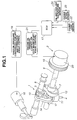
- a hybrid vehicle includes internal combustion engine 31 having a variable valve timing and lift control apparatus consisting of lift and operation angle varying mechanism 1 capable of varying a lift and operation angle of intake valve 4 and maximum lift phase varying mechanism 2 capable of varying a maximum lift phase of intake valve 4, i.e., capable of advancing or retarding a phase of intake valve 4 relative to a rotational phase of crankshaft 31a of engine 31.
- Lift and operation angle varying mechanism 1 is structurally the same as that disclosed in Japanese Patent Provisional Publication No. 11-107725 which was assigned to the same assignee of this application, so that only brief description will be made thereto hereinlater.
- Lift and operation angle varying mechanism 1 includes hollow drive shaft 6 rotatably supported on cylinder head 3 by cam brackets 5, eccentric cam 7 force-fitted or otherwise fixedly attached to drive shaft 6, control shaft 8 disposed above and in parallel with drive shaft 6 and rotatably supported on cylinder head 3 by above described cam brackets 5, rocker arm 10 mounted on eccentric cam portion 9 of control shaft 8 for oscillating motion, and oscillation cam 12 engaging tappet 11 provided to an upper end portion of intake valve 4.
- Eccentric cam 7 and rocker arm 10 are operatively connected by pivotal link 13, and rocker arm 10 and oscillation cam 12 are operatively connected by connecting rod 14.
- Drive shaft 6 is driven by crankshaft 31a of engine 31 by way of a timing chain or timing belt (not shown).
- Eccentric cam 7 has a circular external surface the center of which is offset from a rotational axis of drive shaft 6 by a predetermined amount. On the circular external surface is rotatably fitted or mounted annular base portion 13a of pivotal link 13.
- Rocker arm 10 is mounted at a central portion thereof on eccentric cam portion 9 and has an end portion to which protruded arm portion 13b of above described pivotal link 13 is pivotally connected and another end portion to which an upper end portion of connecting rod 14 is pivotally connected.
- Eccentric cam portion 9 has a geometric center which is offset from the rotational axis of control shaft 8 so that an axis of oscillation of rocker arm 10 varies depending upon a variation of a rotational position or phase of control shaft 8.
- Oscillation cam 12 is rotatably mounted on drive shaft 6 and has laterally protruded end portion 12a to which a lower end portion of connecting link 14 is pivotally connected.
- Oscillation cam 12 has at its lower side thereof basic circular or dwell surface 15a and cam or lift surface 15b extending from basic circular surface 15a toward above described end portion 12b so as to have a predetermined curved profile.
- Basic circular surface 15a and cam surface 15b are brought into engagement with the upper surface of tappet 11 in response to oscillation of oscillation cam 12.
- basic circular surface 15a serves as a base circle area that regulates an amount of lift to zero.
- oscillation cam 12 is turned or rotated to bring cam surface 15b serving as a lift or rise area into contact with tappet 11, there is caused a lift of intake valve 4 which increases gradually with further rotation of oscillation cam 12.
- a small ramp area is provided between the basic circular area and the lift area.
- Control shaft 8 is constructed so as to be rotatable within a predetermined rotational angle range by being driven by hydraulic, lift and operation angle control actuator 16 installed on an end of control shaft 8 as shown in Fig. 1.
- Supply of hydraulic pressure to actuator 16 is performed by first hydraulic pressure controller 18 in response to a control signal from engine control unit (ECU) 17.
- ECU engine control unit
- lift and operation angle varying mechanism 1 will now be described.
- Rotation of drive shaft 6 causes pivotal link 13 to move up and down by the operation of eccentric cam 7.
- rocker arm 10 is caused to oscillate.
- This oscillating movement of rocker arm 10 causes oscillation cam 12 to oscillate.
- tappet 11 is caused to move up and down, causing intake valve 4 to open and close.
- eccentric cam portion 9 when eccentric cam portion 9 is generally positioned in a higher place when observed in Fig. 2, i.e., when the geometric center of eccentric cam portion 9 is located above the rotational axis of control shaft 8, rocker arm 10 is bodily moved into a higher place, thus causing end portion 12a of oscillation cam 12 to be moved into a higher position.
- cam surface 15b when oscillation cam 12 is rotated into the initial position, cam surface 15b is caused to incline away from tappet 11.
- basic circular surface 15a is brought into contact with tappet 11 for a longer period
- cam surface 15b is brought into contact with tappet 11 for a shorter period. Accordingly, the amount of lift is small, and an angular range from an opening timing to a closing timing, i.e., the operation angle is reduced.
- eccentric cam portion 9 is generally positioned in a lower place when observed in Fig. 2, rocker arm 10 is bodily moved into a lower place, thus causing end portion 12a of oscillation cam 12 to be moved into a lower position.
- oscillation cam 12 when oscillation cam 12 is rotated into the initial position, cam surface 15b is caused to incline toward tappet 11. Accordingly, when oscillation cam 12 oscillates in response to rotation of drive shaft 6, the place where oscillation cam 12 is brought into contact with tappet 11 changes immediately thereafter from basic circular surface 15a to cam surface 15b. Accordingly, the amount of lift becomes larger and the operation angle is enlarged.
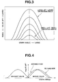
- the lift and operation angle characteristics of intake valve 4 can be varied continuously as shown in Fig. 3. Namely, both of the lift and operation angle can be increased and decreased continuously and at the same time.
- lift and operation angle varying mechanism 1 the opening and closing timings are varied so as to be nearly symmetrical with respect to the maximum lift phase, in response to a variation of the lift and operation angle.
- maximum lift phase varying mechanism 2 includes sprocket 19 provided to a front end portion of drive shaft 6, and hydraulic, phase varying actuator 20 for rotating sprocket 19 relative to drive shaft 6 within a predetermined angular range.
- Sprocket 19 is drivingly connected to crankshaft 31a by way of the timing chain or timing belt (not shown) so as to be rotatable in timed relation to crankshaft 31a.
- Supply of oil pressure to actuator 20 is controlled by second oil pressure controller 21 in response to a signal from engine control unit (ECU) 17.
- ECU engine control unit
- Maximum lift phase varying mechanism 2 is not limited to the hydraulic type but can have various other structures such as one utilizing an electromagnetic actuator.
- Lift and operation angle varying mechanism 1 and maximum lift phase varying mechanism 2 can be open-loop controlled by using sensors (not shown) for detecting an actual lift, operation angle and maximum lift phase or can be simply closed-loop controlled in response to an engine operating condition.
- Engine control unit (ECU) 17 determines the control signals to be supplied to actuators 16 and 20 on the basis of an engine load, engine speed and oil and coolant temperatures detected by engine load sensor 22, engine speed sensor 23 and oil and coolant temperature sensor 24, respectively.
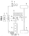
- the hybrid vehicle has internal combustion engine 31 which is provided with the above described variable valve timing and lift control apparatus.
- starting motor 32 which has both functions of an electric motor and a generator and is rotatable in timed relation to crankshaft 31a at all times.
- the other end of crankshaft 31a is connected to input shaft 34 of belt type continuously variable transmission 33 by way of electromagnetic clutch 35.
- drive motor 36 which can serve as a generator for producing electric energy by regeneration.
- continuously variable transmission 33 is drivingly connected to driving wheels 38 by way of final reduction gear 37.
- oil pump 40 for supply of oil pressure to continuously variable transmission 33, there is provided oil pump 40 which is driven by auxiliary motor 39.
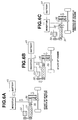
- Figs. 6A to 6C illustrate operations of various portions of the hybrid vehicle at start of the vehicle driven by motor, at start of the engine, and at running of the vehicle driven by engine, respectively.
- the arrows indicate the flow of torque and energy among the components of the hybrid vehicle.
- engine 31 At stoppage or standstill of the vehicle, engine 31 is generally stopped except for the case where the load on engine accessories is large or battery 41 needs to be charged.
- drive motor 36 operated from electric energy stored in battery 41 drives continuously variable transmission 33 to start the vehicle in a suitable transmission gear ratio as shown in Fig. 6A.
- electromagnetic clutch 35 is disengaged.
- engine 31 Since the hybrid vehicle has such a motor drive running mode and engine drive running mode, engine 31 is required to generate electric energy for motor drive running. While electric energy can be obtained by regeneration by drive motor 36 at the time of deceleration of the vehicle, that alone is not sufficient and most of the electric energy for motor drive running depends on that generated by starting motor 32 driven by engine 31. Accordingly, in case engine 31 is started after running of the vehicle by the motor drive running mode, electric energy is first generated for compensating for the electric energy having been consumed during running of the vehicle by the motor drive running mode, so that the load on engine 31 is considerably large even at road load running(hereinafter referred to as R/L running) on a usual road.
- R/L running road load running
- the R/L running is herein used to indicate running of the vehicle wherein the engine speed and the engine load are constant and the throttle opening is 1/4 of full throttle.
- the thermal efficiency of an internal combustion engine is improved when the load becomes higher.
- it is effective for improving the efficiency of the overall engine to make the engine produce a driving force necessary both for generation of electric energy and for driving of the vehicle when the load on the engine is in a relatively high range.
- Such production of a driving force, a so-called engine idling stop and regeneration constitute three major factors for improving the thermal efficiency of the hybrid vehicle.
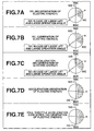
- Fig. 7 shows an optimal control of the opening and closing timings of intake valve 4 with a view to improving the thermal efficiency of engine 31 mainly at running of the vehicle during which electric energy is generated.
- the control is executed by a control program incorporated in the ECU 17 in Fig. 1.
- the intake valve is operated so as to have such performance characteristics shown in Fig. 7A, i.e., intake valve 4 has a small lift and small operation angle, the maximum lift phase (i.e., phase where a maximum lift is obtained) ⁇ is located so as to be closer to the top dead center (TDC) than the bottom dead center (BDC), the intake valve opening timing (IVO) is adjacent the TDC, an overlap is set at a small value so that the amount of remaining gas is small, and the intake valve closing timing (IVC) is considerably earlier than the bottom dead center (BDC).
- TDC top dead center
- BDC bottom dead center
- IVO intake valve opening timing
- IVC intake valve closing timing
- the IVC takes the position indicated by the dotted line in Fig. 7A.
- the actual compression ratio is lowered and therefore the combustion speed becomes slower, thus causing deteriorated combustion.
- the intake valve has a small lift and a small operation angle according to the present invention, the actual compression ratio is lowered.
- the gas flow is made considerably larger as compared with that by the large lift and large operation angle.
- the combustion speed is made higher, thus making it possible to prevent deterioration of combustion and therefore enabling a good fuel consumption to be attained by the effect of a reduced pumping loss and a reduced friction resulting from the small lift and small operation angle.
- the driving force or torque required for driving of the vehicle is the same as that at the above described R/L running but a load for generation of electric energy is applied to engine 31 so that the load on engine 31 is nearly equal to that at the time of acceleration.
- intake valve 4 is operated so as to have such characteristics as shown in Fig. 7B. Since the amount of intake mixture is increased as compared with that by the characteristics shown in Fig. 7A, the lift and operation angle are a little increased but still held at a low level. Further, the control features that maximum lift phase ⁇ is advanced for thereby enlarging the overlap.
- the intake valve has such characteristics as shown in Fig. 7C.
- the control of engine 31 can be the same as that described with reference to Fig. 7B.
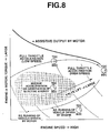
- Fig. 8 shows an overall control map which is incorporated the ECU 17.
- a motor drive mode is selected when the vehicle speed is in a low speed range and the amount of electric energy stored in battery 41 is sufficient.
- engine 31 is started to shift the motor drive running mode to the engine drive running mode.
- the operation of the engine is controlled so as to be included within a screened area. In this instance, the torque produced by drive motor 36 is subtracted from the torque produced by engine 31.
- the operation of engine 31 is controlled so as to be included within the screened area similarly as described above.
- the operation of engine 31 is controlled within a portion of the screened area which is adjacent a full throttle acceleration area.
- an assist by drive motor 36 can be available, so that the torque produced by drive motor 36 is added to the torque produced by engine 31.
- the valve lift is adapted to increase gradually in response to an increase of the amount of intake mixture (i.e., engine speed and load).
- Fig. 9 shows an example of control in accordance with an accel opening degree.
- the control is executed by a control program incorporated in the ECU 17 in Fig. 1.
- This is an example in which generation of electric energy for charging of battery 41 is performed at the time of R/L running. Generation of electric energy is continued until the accel opening degree increases so as to shift the running mode of the vehicle to a slow acceleration mode.
- an overlap of intake valve 4 is large, and the IVC is regulated to an advance side which is advanced more than the BDC.
- requirement for increase of an output of engine 31 can be met by first reducing the amount of electric energy generated by starting motor 32 (i.e., motor B in Fig. 9).
- intake valve 4 is shifted to such intake valve opening and closing characteristics that enable engine 31 to produce as large a torque as possible.
- an assist of a motor drive is used.
- transition e.g., when the vehicle is shifted from the R/L running mode to the rapid acceleration mode
- the assist of motor drive is used a little earlier for thereby attaining a good acceleration feel.
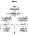
- Fig. 10 shows the flowchart for control of the IVO and IVC (i.e., lift and operation angle) and maximum lift phase ⁇ of the intake valve 4.
- the control is executed by a control program incorporated in the ECU 17 in Fig. 1.
- step S1 the engine operating conditions such as an engine speed and throttle opening degree are detected.
- step S2 it is determined whether or not the quantity of electricity stored in battery 41 is equal to or larger than a predetermined value. If an affirmative decision (Yes) is obtained in step S2, the control flow goes to step S3. If a negative decision (No) is obtained in step S2, the control flow goes to step S6.
- step S3 the set values of IVO, IVC and maximum lift phase ⁇ for running of vehicle driven by engine 31 where electric energy is not generated are read from a control map.
- actuators 16 and 20 are operated for regulating the IVO, IVC and maximum lift phase ⁇ to the set values read in step S3.
- step S6 the set values of IVO, IVC and maximum lift phase ⁇ for running of the vehicle driven by drive motor 36 where electric energy is generated are read from the control map.
- actuators 16 and 20 are operated for regulating the IVO, IVC and maximum lift phase ⁇ to the set values read in step S6.
- the maximum lift phase is regulated to a retard side in preference to enlargement of the lift and the operation angle.
Applications Claiming Priority (2)
| Application Number | Priority Date | Filing Date | Title |
|---|---|---|---|
| JP2000269760 | 2000-09-06 | ||
| JP2000269760A JP3536798B2 (ja) | 2000-09-06 | 2000-09-06 | 車両用内燃機関の制御装置 |
Publications (3)
| Publication Number | Publication Date |
|---|---|
| EP1186753A2 true EP1186753A2 (de) | 2002-03-13 |
| EP1186753A3 EP1186753A3 (de) | 2002-06-19 |
| EP1186753B1 EP1186753B1 (de) | 2006-04-26 |
Family
ID=18756311
Family Applications (1)
| Application Number | Title | Priority Date | Filing Date |
|---|---|---|---|
| EP01121278A Expired - Lifetime EP1186753B1 (de) | 2000-09-06 | 2001-09-05 | Steuerungssystem und -verfahren eines Hybridfahrzeugs mit Regelung der Hubverstellung eines Einlassventils |
Country Status (3)
| Country | Link |
|---|---|
| EP (1) | EP1186753B1 (de) |
| JP (1) | JP3536798B2 (de) |
| DE (1) | DE60119052T2 (de) |
Cited By (9)
| Publication number | Priority date | Publication date | Assignee | Title |
|---|---|---|---|---|
| WO2002049868A1 (de) * | 2000-12-21 | 2002-06-27 | Robert Bosch Gmbh | Verfahren zum betrieb eines verbrennungsmotors |
| WO2003010023A1 (en) * | 2001-07-26 | 2003-02-06 | Toyota Jidosha Kabushiki Kaisha | Vehicle control device and control method therefor |
| CN100395433C (zh) * | 2003-12-24 | 2008-06-18 | 本田技研工业株式会社 | 气门升程可变机构的驱动装置 |
| WO2011127892A1 (de) * | 2010-04-12 | 2011-10-20 | Schaeffler Technologies Gmbh & Co. Kg | Kegelscheibenumschlingungsgetriebe |
| US8307926B2 (en) * | 2005-11-24 | 2012-11-13 | Toyota Jidosha Kabushiki Kaisha | Hybrid vehicle |
| US20150175147A1 (en) * | 2013-12-19 | 2015-06-25 | Toyota Jidosha Kabushiki Kaisha | Hybrid vehicle |
| US9527501B2 (en) | 2013-11-12 | 2016-12-27 | Toyoda Jidosha Kabushiki Kaisha | Hybrid vehicle |
| US9909512B2 (en) | 2014-02-25 | 2018-03-06 | Toyota Jidosha Kabushiki Kaisha | Hybrid vehicle and control method for hybrid vehicle |
| DE102004048606B4 (de) | 2004-10-06 | 2019-05-09 | Robert Bosch Gmbh | Hybrider Antriebsstrang für ein Kraftfahrzeug |
Families Citing this family (8)
| Publication number | Priority date | Publication date | Assignee | Title |
|---|---|---|---|---|
| JP4896546B2 (ja) * | 2006-03-07 | 2012-03-14 | 本田技研工業株式会社 | 電動機を具備する車両 |
| US7527028B2 (en) | 2006-03-09 | 2009-05-05 | Ford Global Technologies, Llc | Hybrid vehicle system having engine with variable valve operation |
| US7519466B2 (en) * | 2007-05-08 | 2009-04-14 | Gm Global Technology Operations, Inc. | Cam phaser compensation in a hybrid vehicle system |
| DE102008034356B4 (de) * | 2007-07-27 | 2016-08-25 | GM Global Technology Operations LLC (n. d. Ges. d. Staates Delaware) | Nockenverstellungs-Steuersystem und -Verfahren zum Erhöhen des Regenerationswirkungsgrads |
| JP4901677B2 (ja) * | 2007-10-01 | 2012-03-21 | 日立オートモティブシステムズ株式会社 | 可変動弁機構の制御装置 |
| DE102008064538A1 (de) | 2008-12-19 | 2010-06-24 | Dr. Ing. H.C. F. Porsche Aktiengesellschaft | Verfahren zum Betreiben eines Hybridfahrzeuges |
| RU2531533C2 (ru) | 2010-05-12 | 2014-10-20 | Хонда Мотор Ко., Лтд. | Устройство управления для транспортного средства с гибридным приводом |
| JP2015116967A (ja) * | 2013-12-19 | 2015-06-25 | トヨタ自動車株式会社 | ハイブリッド車両 |
Citations (3)
| Publication number | Priority date | Publication date | Assignee | Title |
|---|---|---|---|---|
| JPH11107725A (ja) | 1997-08-07 | 1999-04-20 | Unisia Jecs Corp | 内燃機関の可変動弁装置 |
| JP2000073901A (ja) | 1998-09-02 | 2000-03-07 | Nippon Soken Inc | 内燃機関の燃料供給制御装置 |
| JP2000269760A (ja) | 1999-03-15 | 2000-09-29 | Sony Corp | Agc回路駆動装置 |
Family Cites Families (7)
| Publication number | Priority date | Publication date | Assignee | Title |
|---|---|---|---|---|
| DE3540902A1 (de) * | 1985-11-19 | 1987-04-30 | Bayerische Motoren Werke Ag | Arbeitsverfahren zur steuerung mechanisch-hydraulisch betaetigter ventile fuer kraft- und arbeitsmaschinen |
| US5056378A (en) * | 1989-09-28 | 1991-10-15 | Ford Motor Company | Engine valve control during transmission shifts |
| JP3250483B2 (ja) * | 1996-07-18 | 2002-01-28 | トヨタ自動車株式会社 | 駆動装置 |
| JP3216589B2 (ja) * | 1996-10-29 | 2001-10-09 | トヨタ自動車株式会社 | 動力出力装置,原動機制御装置並びにこれらの制御方法 |
| JP3096446B2 (ja) * | 1997-09-17 | 2000-10-10 | 本田技研工業株式会社 | ハイブリッド車両の制御装置 |
| JP3381613B2 (ja) * | 1998-03-20 | 2003-03-04 | 日産自動車株式会社 | ハイブリッド車両の駆動制御装置 |
| JP3719339B2 (ja) * | 1998-11-09 | 2005-11-24 | 日産自動車株式会社 | 内燃機関の可変動弁制御装置 |
-
2000
- 2000-09-06 JP JP2000269760A patent/JP3536798B2/ja not_active Expired - Lifetime
-
2001
- 2001-09-05 DE DE60119052T patent/DE60119052T2/de not_active Expired - Lifetime
- 2001-09-05 EP EP01121278A patent/EP1186753B1/de not_active Expired - Lifetime
Patent Citations (3)
| Publication number | Priority date | Publication date | Assignee | Title |
|---|---|---|---|---|
| JPH11107725A (ja) | 1997-08-07 | 1999-04-20 | Unisia Jecs Corp | 内燃機関の可変動弁装置 |
| JP2000073901A (ja) | 1998-09-02 | 2000-03-07 | Nippon Soken Inc | 内燃機関の燃料供給制御装置 |
| JP2000269760A (ja) | 1999-03-15 | 2000-09-29 | Sony Corp | Agc回路駆動装置 |
Cited By (12)
| Publication number | Priority date | Publication date | Assignee | Title |
|---|---|---|---|---|
| WO2002049868A1 (de) * | 2000-12-21 | 2002-06-27 | Robert Bosch Gmbh | Verfahren zum betrieb eines verbrennungsmotors |
| US6986335B2 (en) | 2000-12-21 | 2006-01-17 | Robert Bosch Gmbh | Method for operating an internal combustion engine |
| WO2003010023A1 (en) * | 2001-07-26 | 2003-02-06 | Toyota Jidosha Kabushiki Kaisha | Vehicle control device and control method therefor |
| CN100395433C (zh) * | 2003-12-24 | 2008-06-18 | 本田技研工业株式会社 | 气门升程可变机构的驱动装置 |
| DE102004048606B4 (de) | 2004-10-06 | 2019-05-09 | Robert Bosch Gmbh | Hybrider Antriebsstrang für ein Kraftfahrzeug |
| US8307926B2 (en) * | 2005-11-24 | 2012-11-13 | Toyota Jidosha Kabushiki Kaisha | Hybrid vehicle |
| WO2011127892A1 (de) * | 2010-04-12 | 2011-10-20 | Schaeffler Technologies Gmbh & Co. Kg | Kegelscheibenumschlingungsgetriebe |
| CN102869529A (zh) * | 2010-04-12 | 2013-01-09 | 舍弗勒技术股份两合公司 | 锥盘无级变速器 |
| CN102869529B (zh) * | 2010-04-12 | 2015-11-25 | 舍弗勒技术股份两合公司 | 锥盘无级变速器 |
| US9527501B2 (en) | 2013-11-12 | 2016-12-27 | Toyoda Jidosha Kabushiki Kaisha | Hybrid vehicle |
| US20150175147A1 (en) * | 2013-12-19 | 2015-06-25 | Toyota Jidosha Kabushiki Kaisha | Hybrid vehicle |
| US9909512B2 (en) | 2014-02-25 | 2018-03-06 | Toyota Jidosha Kabushiki Kaisha | Hybrid vehicle and control method for hybrid vehicle |
Also Published As
| Publication number | Publication date |
|---|---|
| DE60119052D1 (de) | 2006-06-01 |
| EP1186753B1 (de) | 2006-04-26 |
| DE60119052T2 (de) | 2006-08-31 |
| EP1186753A3 (de) | 2002-06-19 |
| JP3536798B2 (ja) | 2004-06-14 |
| JP2002081330A (ja) | 2002-03-22 |
Similar Documents
| Publication | Publication Date | Title |
|---|---|---|
| EP1186753B1 (de) | Steuerungssystem und -verfahren eines Hybridfahrzeugs mit Regelung der Hubverstellung eines Einlassventils | |
| JP3979081B2 (ja) | 内燃機関の燃焼制御システム | |
| US6691655B2 (en) | Control system and method for an internal combustion engine | |
| US7146966B2 (en) | Cylinder cutoff control apparatus of internal combustion engine | |
| US6732682B2 (en) | Control system and method for an internal combustion engine | |
| JP4385509B2 (ja) | 車両用内燃機関の制御装置 | |
| US6502535B2 (en) | Valve timing and lift control system | |
| JP4649714B2 (ja) | 車両用内燃機関の制御装置 | |
| US7481199B2 (en) | Start control apparatus of internal combustion engine | |
| JP4857685B2 (ja) | エンジンの始動方法及びエンジンの始動装置 | |
| JP5168167B2 (ja) | 車両用内燃機関の制御装置 | |
| JP2019035359A (ja) | 内燃機関の可変動作システム及びその制御装置 | |
| JP4389555B2 (ja) | 可変圧縮比内燃機関の制御装置 | |
| JP4590746B2 (ja) | 内燃機関の可変動弁装置 | |
| JP7361221B2 (ja) | 可変バルブタイミング装置の制御装置 | |
| JP4379273B2 (ja) | 可変圧縮比機構を備えた内燃機関 | |
| JP6409559B2 (ja) | 車両の制御装置 | |
| JP4383155B2 (ja) | 内燃機関の減速制御装置及び減速制御方法 | |
| JP4238710B2 (ja) | 内燃機関の吸気制御装置 | |
| JP2003328790A (ja) | エンジンの動弁制御装置 | |
| JP5104473B2 (ja) | 内燃機関の制御方法および同装置 |
Legal Events
| Date | Code | Title | Description |
|---|---|---|---|
| PUAI | Public reference made under article 153(3) epc to a published international application that has entered the european phase |
Free format text: ORIGINAL CODE: 0009012 |
|
| 17P | Request for examination filed |
Effective date: 20010905 |
|
| AK | Designated contracting states |
Kind code of ref document: A2 Designated state(s): AT BE CH CY DE DK ES FI FR GB GR IE IT LI LU MC NL PT SE TR |
|
| AX | Request for extension of the european patent |
Free format text: AL;LT;LV;MK;RO;SI |
|
| PUAL | Search report despatched |
Free format text: ORIGINAL CODE: 0009013 |
|
| AK | Designated contracting states |
Kind code of ref document: A3 Designated state(s): AT BE CH CY DE DK ES FI FR GB GR IE IT LI LU MC NL PT SE TR |
|
| AX | Request for extension of the european patent |
Free format text: AL;LT;LV;MK;RO;SI |
|
| AKX | Designation fees paid |
Designated state(s): DE FR GB |
|
| GRAP | Despatch of communication of intention to grant a patent |
Free format text: ORIGINAL CODE: EPIDOSNIGR1 |
|
| GRAS | Grant fee paid |
Free format text: ORIGINAL CODE: EPIDOSNIGR3 |
|
| GRAA | (expected) grant |
Free format text: ORIGINAL CODE: 0009210 |
|
| AK | Designated contracting states |
Kind code of ref document: B1 Designated state(s): DE FR GB |
|
| REG | Reference to a national code |
Ref country code: GB Ref legal event code: FG4D |
|
| RIC1 | Information provided on ipc code assigned before grant |
Ipc: B60K 6/04 20060101ALI20060307BHEP Ipc: F02D 13/02 20060101ALI20060307BHEP Ipc: F01L 13/00 20060101AFI20060307BHEP |
|
| REF | Corresponds to: |
Ref document number: 60119052 Country of ref document: DE Date of ref document: 20060601 Kind code of ref document: P |
|
| ET | Fr: translation filed | ||
| PLBE | No opposition filed within time limit |
Free format text: ORIGINAL CODE: 0009261 |
|
| STAA | Information on the status of an ep patent application or granted ep patent |
Free format text: STATUS: NO OPPOSITION FILED WITHIN TIME LIMIT |
|
| 26N | No opposition filed |
Effective date: 20070129 |
|
| REG | Reference to a national code |
Ref country code: FR Ref legal event code: PLFP Year of fee payment: 16 |
|
| REG | Reference to a national code |
Ref country code: FR Ref legal event code: PLFP Year of fee payment: 17 |
|
| REG | Reference to a national code |
Ref country code: FR Ref legal event code: PLFP Year of fee payment: 18 |
|
| PGFP | Annual fee paid to national office [announced via postgrant information from national office to epo] |
Ref country code: GB Payment date: 20200826 Year of fee payment: 20 Ref country code: FR Payment date: 20200812 Year of fee payment: 20 Ref country code: DE Payment date: 20200826 Year of fee payment: 20 |
|
| REG | Reference to a national code |
Ref country code: DE Ref legal event code: R071 Ref document number: 60119052 Country of ref document: DE |
|
| REG | Reference to a national code |
Ref country code: GB Ref legal event code: PE20 Expiry date: 20210904 |
|
| PG25 | Lapsed in a contracting state [announced via postgrant information from national office to epo] |
Ref country code: GB Free format text: LAPSE BECAUSE OF EXPIRATION OF PROTECTION Effective date: 20210904 |