EP1180556A1 - Procédé pour la fabrication d'un tissu double peluche - Google Patents
Procédé pour la fabrication d'un tissu double peluche Download PDFInfo
- Publication number
- EP1180556A1 EP1180556A1 EP00117599A EP00117599A EP1180556A1 EP 1180556 A1 EP1180556 A1 EP 1180556A1 EP 00117599 A EP00117599 A EP 00117599A EP 00117599 A EP00117599 A EP 00117599A EP 1180556 A1 EP1180556 A1 EP 1180556A1
- Authority
- EP
- European Patent Office
- Prior art keywords
- binding
- weft
- threads
- binding warp
- group
- Prior art date
- Legal status (The legal status is an assumption and is not a legal conclusion. Google has not performed a legal analysis and makes no representation as to the accuracy of the status listed.)
- Granted
Links
Images


Classifications
-
- D—TEXTILES; PAPER
- D03—WEAVING
- D03D—WOVEN FABRICS; METHODS OF WEAVING; LOOMS
- D03D27/00—Woven pile fabrics
- D03D27/02—Woven pile fabrics wherein the pile is formed by warp or weft
- D03D27/10—Fabrics woven face-to-face, e.g. double velvet
Definitions
- the invention relates to a method for producing a double-pile fabric on a double-pile weaving machine with at least two weft insertion levels, using weft threads, filling warp threads and binding warp threads for the Training of the basic goods of the lower and upper goods as well as of Choosing pile threads per warp course for the formation of the patterned pile layer between the two basic goods, the respective non-patterned pile threads stretched largely in the basic goods of the upper and / or lower goods are involved and their patterning pile threads alternate between Weft threads of the upper and lower goods are opened; the weft threads in at least two different weft insertion levels, in an at least two-speed repeat, at least as a back shot or be entered as an internal shot in both basic goods; in which each basic product groups of staggered in the warp direction Binding warp threads are assigned, the binding warp threads one Group within a weave repeat all wefts related to encompass a basic fabric from the outside, with each binding warp thread one Group
- a method of this type has become known from EP 628 649 A1.
- the binding chains are regularly arranged in groups of two binding warp threads.
- One group is assigned to a warp course.
- Each warp course has such a group of binding warp threads, at least one fill warp thread and a choir of pile threads.
- a group of binding warp threads is characterized in that, within its binding repeat, it holds all back wefts and all inside wefts in their area of action on the stretched-in filling chain and on the stretched-in dead poles. It is customary to have the individual binding warp threads of a group follow a specific binding pattern within a repeat.
- the diagonal section let's call it the holding section, of the binding warp thread pulled the intermediate binding point very tightly to the previously formed basic fabric.
- the shorter section which runs through the basic fabric, we call it the compensation section, then fixed the position of the binding warp thread in the basic material, so that the finished fabric could not loosen again in the department when the binding warp thread tension was released.
- Such a bond already guarantees a usable quality of the binding of the pole pieces.
- the shot density is relatively narrow.
- the asymmetrically integrated binding chain means that the shots supporting and supporting the pole handles are shifted in the chain direction along the filling chain or along the dead poles. The direction of exit of the pole handles regularly deviates up to 10 ° and more from the vertical position to the base product.
- the reed is aligned accordingly, they regularly emerge vertically from the base fabric. It is possible to achieve the treading properties usually required even with a lower pole height and even with a possibly lower pole density. At the same time, the consumption of binding warp threads is reduced - depending on the binding finally selected, very significantly. The use of an additional warp beam on the weaving machine is avoided.
- the modification of the method according to claim 2 makes it possible to increase the length of the holding sections without having to provide additional measures for binding individual shots.
- the measure according to claim 3 enables a further, significant reduction in the consumption of binding warp threads with reliable securing integration of all weft threads and with the securing of a uniform binding length of all binding warp threads. It has been shown that the tension of the binding warp threads can also be maintained over longer sections if one of the binding warp threads follows a section with a different type of binding for more than four tours.
- the pre-tension and the elasticity of the warp threads as well as the individual loading by the warp stop motion are sufficient to always ensure the minimum tension of the warp threads.
- the weft threads of large thickness which are used in the usual way on carpet weaving machines, do not necessarily require a binding in every warp course in order to secure their position. It is possible to use only one single warp thread in each warp course and to distribute the warp threads of a group - according to the current state of knowledge - over up to four adjacent warp courses. The material saving is very clear.
- the pile density in the weft direction and warp direction can be additionally increased.
- the measure according to claim 4 ensures a further reduction in the need for binding warp threads.
- the use of compensating sections enables uniform binding lengths of the binding warp threads, on the one hand, and, on the other hand, an immovable binding of the inner wefts that guide the pile legs, especially when choosing symmetrical binding patterns for the binding chain.
- the binding variant according to claim 5 enables not only a high weft and pile density in the warp direction, but also optimal support of the pole legs in the weft direction.
- Long binding sections securely clamped in the finished base material and symmetrical loading of the weft threads by the binding chain ensure the vertical integration of the pole legs.
- the shaft drive can also be realized with a conventional eccentric machine.
- Sufficient stability of the basic fabric can also be achieved if only one binding warp thread is arranged in each warp course.
- the method according to claim 6 enables additional savings in binding warp thread.
- Claim 7 shows a possibility in which large clamping lengths of the pole legs can also be achieved with the method according to the invention.
- Claim 8 describes a procedure in which a somewhat higher consumption of binding warp threads is accepted in the interest of greater stability of the base fabric.
- the upright poles are also guaranteed here.
- Claim 9 describes an almost equivalent solution variant to Claim 5.
- the variant according to claim 10 enables vertical pole legs while ensuring a very high stability of the base fabric and a high pile density in the warp direction. A restriction with regard to the density in the weft direction is avoided by distributing the binding warp threads over four warp courses - according to claim 3.
- Claim 11 describes a method with which properties similar to those described in relation to claim 10 are achieved.
- Independent claim 12 leads to the same effects as the method according to claim 1 with regard to the saving of binding warp threads.
- the clamping of the woven-in part of the binding warp threads is not available or only to a limited extent.
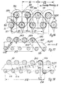
- the double carpet fabric shown in Fig. 1 consists of an upper and a lower base fabric, the upper fabric OW and the lower fabric UW, and from the pattern threads PM, which alternate regularly between the upper and lower base fabric, and which are centered between the upper and lower fabrics after the weaving process
- Bottomware UW can be separated.
- Each of the basic goods OW, UW contains filling warp threads FK running in the warp direction and parallel, non-patterning pile threads, which are referred to below as dead poles PT or dead pole strand.
- These two thread groups FK, PT are held on the outside by back wefts SR and on the inside by inside wefts SI.
- the position of the back SR and inner wefts SI is fixed by binding warp threads B, (in Fig. 1: B1, B2).
- the binding warp threads B are arranged in groups.
- the size of the group normally fluctuates between two (e.g. B1, B2) and four (e.g. B13 to B16) binding warp threads B.
- the number of binding warp threads B of a group depends on the minimum number of threads required To bind all back wefts SR and inner wefts SI to the basic fabric once within a binding repeat R. (Adjacent groups can also complement each other in terms of one or more binding sites.)
- a repeat of the binding warp threads B we usually find at least one holding section Y and at least one compensating section Z.
- the first holding section Y1 of the binding warp thread B1 of the group B1, B2 shown in FIG. 1 begins after the inner weft SI shown at the top left.
- this binding warp thread B1 is guided to the following inner weft SI and from there in the same plane to the next inner weft SI. If all binding warp threads B1, B2 of the group bind with the same binding length, the binding repeat of a group would already have ended here. In the present case, however, the second binding warp thread B2 binds in a different way. It changes from one weft opposite the first pair of weft threads to the next, which is entered three weft entries later.
- This binding warp thread B2 brings the necessary longitudinal tension into the base fabric and ensures that the back wefts SR, which carry the pole handles and the inner wefts SI, which carry the pole handles, pull so closely together that an inclined position of the pile handles is avoided with certainty. So that the binding length of both binding warp threads B1, B2 is guaranteed within one repeat, both binding warp threads B1, B2 change twice within one repeat R - if necessary in a special interchangeable section W, they mutually change their type of binding.
- the holding section Y1, Y2 In both types of binding, the holding section Y1, Y2 and also extends the respective compensation section Z1, Z3 over three weft insertion cycles.
- the Overall report is due to the changing sections W z. B. 20 or 28 Weft insertion cycles. After every three or five. Guns change regularly two binding warp threads B1, B2 inwards or from the back plane vice versa.
- the size of the repeat R and the individual binding sections X1, X2 should be chosen so that a temporary loosening of individual Binding warp threads B1, B2 of a group can be avoided with certainty.
- the tension of the binding warp threads B should be in front of the entrance to the shedding zone are monitored and a voltage value of 2 to 4 N is not below.
- the binding warp threads B1, B2 of the group can be reduced to two in the present case adjacent warp courses K1, K2 can be distributed (Fig. 2). You hold up despite this distribution the relatively voluminous back shots SR on the filling chain FK and the internal shots SI are sufficiently secure on the dead pole strands PT in of the respective basic goods OW or UW.
- FIGS. 2 to 8 binding forms on upper goods OW are shown in which the basic goods only have back SR and inner wefts SI. 9 to 15, on the other hand, show basic goods, ie upper goods OW, which also have intermediate wefts SZ (SZ1, SZ2, SZ3).
- FIG. 2 shows a binding, as also described with reference to FIG. 1 has been. Only the changing sections W are positioned somewhat differently here and designed. The interchangeable sections W are in addition to those in FIG Holding sections Y1, Y2 and the compensating sections Z1, Z2 are provided.
- FIG. 3 shows a regular, paired binding the back SR and interior shots SI. It fulfills the invention Goal setting with very simple means.
- the first one included Back shot SR retains its position specified with the stop until the second back shot of this couple is struck.
- the one in front of the pair Binding of the back shots brought up by the last inner shot SI Holding section Y3 is clamped in the already finished fabric in such a way that this thread section hardly have an elastic component can move the last entered SR back shot laterally could.
- the pole legs are not deflected and are almost vertical in the basic commodity.
- the type of weave according to FIG. 4 shows larger sections X3, X4 with different types of weave of the warp threads B5, B6, B7, B8.
- Two binding warp threads B5, B6 regularly bind in pairs via back wefts SR or inner wefts SI.
- Their holding sections Y4 and their compensating sections Z4 extend over five weft insertion cycles each.
- the two binding warp threads B7, B8 each bind only via one weft, one back weft SR or one inner weft SI.
- FIG. 5 shows a form of binding in which the individual binding warp threads B9, B10, B11, B12 bind almost symmetrically and regularly according to a single type of binding.
- a deflection of the pole limbs in any direction is reliably avoided and the individual binding warp threads B9, B10, B11, B12 of a group are preferably arranged in pairs in adjacent warp courses K1, K2. It is also possible to arrange these binding warp threads B9, B10, B11, B12 individually in four adjacent warp courses.
- the holding sections Y5 comprise five weft entries, while the equalizing sections Z5 are completed after three tours.
- the embodiment according to FIG. 6 is essentially comparable to FIG. 5.
- the difference is that the binding warp threads B13, B14, B15, B16 instead of tying single wefts over weft pairs.
- this version becomes a very high fabric density with absolutely vertical alignment the pole leg reached.
- Weft threads significantly reduce the need for warp threads, if the individual binding warp threads of a group are distributed over several warp courses become.
- the binding according to Fig. 7 differs from Fig. 6 in that the number that of a binding warp thread B17, B18, B19, B20 in the area of the back wefts SR and in the area of the internal wefts Si is further increased.
- the back wefts SR or inner wefts SI are each in plain weave fixed.
- the holding section Y7 and also the compensation section Z7 extends each about seven shots.
- FIGS. 9 to 11 show the regular incorporation of the weft threads by binding warp threads B25, B26, B27, the binding warp threads fixing the weft threads SR, Si individually and almost alternately in a symmetrical manner using the repeat R9, R10, R11.
- the binding warp threads B25, B26, B27, B28 of each of these basic goods can be arranged in one to four warp courses in relation to a group.
- a weave repeat R12 of a binding warp thread B29, B30 consists of holding sections Y12 and compensating sections Z12 with different types of weave according to the type of plain weave between the inner SI and intermediate weft SZ3 or between the back SR and intermediate weft SZ3. All back wefts SR and all inner wefts Si are symmetrically loaded by the binding warp threads B29, B30.
- the binding length of the binding warp threads B29, B30 of this group is compensated according to the example in FIG. 2 by two changing sections W.
- the binding according to Fig. 13 is essentially comparable to the binding according to Fig. 7. However, the changing sections W are shortened.
- the holding sections Y13 extend over five weft insertion cycles; the compensation sections Z13 as well.
- the additional intermediate wefts SZ1 which press the filling chain FK against the back wefts SR, ensure a slight curvature of the filling chain FK, which additionally hinders the sliding of the back wefts SR in the warp direction.
- the intermediate shots SZ2, SZ3 serve here for the additional fixation of the SR back shots without the binding warp threads B34, B35, B36 or B37, B38, B39 regularly overlap the entire cross-section of the basic goods OW.
- the accumulation of internal tensions in the binding chains B1, B2 is avoided by the wrap friction in connection with the friction due to the clamping effect within the finished fabric.
- Crossing points of the binding warp threads B1, B2 are avoided at the densest points in the fabric.
- the back wefts are SR or inner wefts SI within the holding sections Y17 (and also in the compensation sections Y7 Fig. 7) in their plane to each other by means of plain weave held.
- All back shots SR and all inside shots SI are by at least one diagonal binding warp thread section firmly on the Filling chain FK or held at the dead poles PT.
- the basic commodity is on this Way very stable.
- the longitudinal forces (in the direction of the chain) in this system are additionally through the diagonal thread section within the holding section Y17 applied.
- the clamping forces also act here this thread section in the finished fabric positive.
- the back and Internal shots SR, Si remain in the finished fabric in the position in which they are be positioned at the stop (stop direction A).
- Fig. 18 shows a binding variant according to the invention, which despite the Asymmetry of the binding pattern a vertical integration of the pole legs allows.
- the binding warp thread B40 is attached to the inside weft SI4 within the holding section Y18 over eight weft insertion cycles in the area of the dead poles PT and the filling chain FK. In this Area, it is stretched in the finished fabric and simultaneously clamped on all sides. The clamping force applied by him acts in the stop direction A. all back shots positioned in its area of action equally. Although the inside wefts SI seem to be just opposite in this binding In practice, no one was charged Displacement in that direction.
- the cause is very likely in that the clamping forces on the long holding section Y18 are so large within the finished fabric that a shift of the Internal shots do not occur during a repeated shot.
- the Polhenkel are also regularly vertical with this asymmetrical binding from the basic goods.
- the weave shown in FIG. 18 can also be woven in the opposite direction with similar effects.
- the asymmetrical pull on the back shots is not able to change the position of the back shots due to the stretched alignment of the compensation section (then this Z18) between the back and the inside shots SR, SI.
- the clamping forces on the binding warp threads B that build up within the finished fabric support this process.
- the almost vertical alignment of the pile thread legs can also be achieved with this variant.
- the results when reaching a high pile density are to be evaluated similarly if a certain repeat length is guaranteed.
- the effects in terms of saving material for the binding chain as a whole are also fully effective in this variant.
Landscapes
- Engineering & Computer Science (AREA)
- Textile Engineering (AREA)
- Woven Fabrics (AREA)
Priority Applications (3)
| Application Number | Priority Date | Filing Date | Title |
|---|---|---|---|
| EP00117599A EP1180556B1 (fr) | 2000-08-16 | 2000-08-16 | Procédé pour la fabrication d'un tissu double peluche |
| DE50011569T DE50011569D1 (de) | 2000-08-16 | 2000-08-16 | Verfahren zur Herstellung eines Doppelpolgewebes |
| US09/903,067 US6502605B2 (en) | 2000-08-16 | 2001-07-11 | Process for the production of a face-to-face carpet fabric |
Applications Claiming Priority (1)
| Application Number | Priority Date | Filing Date | Title |
|---|---|---|---|
| EP00117599A EP1180556B1 (fr) | 2000-08-16 | 2000-08-16 | Procédé pour la fabrication d'un tissu double peluche |
Publications (2)
| Publication Number | Publication Date |
|---|---|
| EP1180556A1 true EP1180556A1 (fr) | 2002-02-20 |
| EP1180556B1 EP1180556B1 (fr) | 2005-11-09 |
Family
ID=8169534
Family Applications (1)
| Application Number | Title | Priority Date | Filing Date |
|---|---|---|---|
| EP00117599A Expired - Lifetime EP1180556B1 (fr) | 2000-08-16 | 2000-08-16 | Procédé pour la fabrication d'un tissu double peluche |
Country Status (3)
| Country | Link |
|---|---|
| US (1) | US6502605B2 (fr) |
| EP (1) | EP1180556B1 (fr) |
| DE (1) | DE50011569D1 (fr) |
Cited By (4)
| Publication number | Priority date | Publication date | Assignee | Title |
|---|---|---|---|---|
| EP1398403A1 (fr) * | 2002-09-11 | 2004-03-17 | N.V. Michel Van de Wiele | Procédé pour tisser un tissu à poils |
| EP1489210A1 (fr) * | 2003-06-21 | 2004-12-22 | SCHÖNHERR Textilmaschinenbau GmbH | Procédé pour la fabrication d'un tissu double peluche sur un métier à tisser double peluche |
| EP1489211A2 (fr) * | 2003-06-21 | 2004-12-22 | SCHÖNHERR Textilmaschinenbau GmbH | Procédé pour la fabrication d'un tissu double peluche sur un métier à tisser double peluche |
| FR2929623A1 (fr) * | 2008-04-03 | 2009-10-09 | Schonherr Textilmaschb | Procede de tissage pour realiser un tapis et tapis obtenu par un tel procede |
Families Citing this family (5)
| Publication number | Priority date | Publication date | Assignee | Title |
|---|---|---|---|---|
| US7520303B2 (en) * | 2005-06-24 | 2009-04-21 | N.V. Michel Van De Wiele | Method for weaving a fabric, fabric woven by means of such a method and weaving machine for weaving such a fabric |
| BE1016883A3 (nl) * | 2005-12-06 | 2007-09-04 | Wiele Michel Van De Nv | Werkwijze voor het vervaardigen van poolweefsels met hoge dichtheid. |
| EP2251467B1 (fr) * | 2009-05-13 | 2013-08-07 | SCHÖNHERR Textilmaschinenbau GmbH | Procédé de tisser simultanément deux étoffes, étoffe tissée selon ce procédé et machine à tisser utilisable avec ce procédé |
| WO2013041938A2 (fr) * | 2011-09-22 | 2013-03-28 | Nv Michel Van De Wiele | Procédé permettant de tisser un tissu à poils |
| EP3702500B1 (fr) * | 2019-02-26 | 2022-04-06 | STÄUBLI BAYREUTH GmbH | Procédé de tissage de tissus à poils et tissu à poils tissé à l'aide d'un tel procédé |
Citations (3)
| Publication number | Priority date | Publication date | Assignee | Title |
|---|---|---|---|---|
| BE675494A (fr) * | ||||
| EP0628649A1 (fr) * | 1993-06-11 | 1994-12-14 | N.V. Michel Van de Wiele | Procédé pour la fabrication du velours face contre face |
| EP0922799A2 (fr) * | 1997-12-09 | 1999-06-16 | N.V. Michel Van de Wiele | Procédé pour tisser un tissu à poil avec une haute densité de poil |
Family Cites Families (5)
| Publication number | Priority date | Publication date | Assignee | Title |
|---|---|---|---|---|
| DE574920C (de) | 1928-11-24 | 1935-05-17 | Karl Petzoldt | Jacquardmaschine |
| FR1401236A (fr) * | 1964-03-04 | 1965-06-04 | Librex Anstalt | Nouveau tapis tissé en double pièce et mode de tissage de ce tapis |
| US3612110A (en) * | 1968-10-22 | 1971-10-12 | Gerald Charles Wildi | Woven tapes |
| BE1004348A3 (nl) * | 1990-06-05 | 1992-11-03 | Wiele Michel Van De Nv | Werkwijze voor het vervaardigen van een dubbelstuktapijtweefsel, in een 2-schotbinding alsmede aldus verkregen weefsels. |
| BE1012004A3 (nl) * | 1997-12-01 | 2000-04-04 | Wiele Michel Van De Nv | Werkwijze voor het vervaardigen van een poolweefsel met grove poolkettingdraden. |
-
2000
- 2000-08-16 EP EP00117599A patent/EP1180556B1/fr not_active Expired - Lifetime
- 2000-08-16 DE DE50011569T patent/DE50011569D1/de not_active Expired - Lifetime
-
2001
- 2001-07-11 US US09/903,067 patent/US6502605B2/en not_active Expired - Lifetime
Patent Citations (3)
| Publication number | Priority date | Publication date | Assignee | Title |
|---|---|---|---|---|
| BE675494A (fr) * | ||||
| EP0628649A1 (fr) * | 1993-06-11 | 1994-12-14 | N.V. Michel Van de Wiele | Procédé pour la fabrication du velours face contre face |
| EP0922799A2 (fr) * | 1997-12-09 | 1999-06-16 | N.V. Michel Van de Wiele | Procédé pour tisser un tissu à poil avec une haute densité de poil |
Cited By (7)
| Publication number | Priority date | Publication date | Assignee | Title |
|---|---|---|---|---|
| EP1398403A1 (fr) * | 2002-09-11 | 2004-03-17 | N.V. Michel Van de Wiele | Procédé pour tisser un tissu à poils |
| BE1015103A3 (nl) * | 2002-09-11 | 2004-10-05 | Wiele Michel Van De Nv | Werkwijze voor het weven van een poolweefsel. |
| US6945280B2 (en) | 2002-09-11 | 2005-09-20 | N. V. Michel Van De Wiele | Method for weaving a pile fabric |
| EP1489210A1 (fr) * | 2003-06-21 | 2004-12-22 | SCHÖNHERR Textilmaschinenbau GmbH | Procédé pour la fabrication d'un tissu double peluche sur un métier à tisser double peluche |
| EP1489211A2 (fr) * | 2003-06-21 | 2004-12-22 | SCHÖNHERR Textilmaschinenbau GmbH | Procédé pour la fabrication d'un tissu double peluche sur un métier à tisser double peluche |
| EP1489211A3 (fr) * | 2003-06-21 | 2005-11-09 | SCHÖNHERR Textilmaschinenbau GmbH | Procédé pour la fabrication d'un tissu double peluche sur un métier à tisser double peluche |
| FR2929623A1 (fr) * | 2008-04-03 | 2009-10-09 | Schonherr Textilmaschb | Procede de tissage pour realiser un tapis et tapis obtenu par un tel procede |
Also Published As
| Publication number | Publication date |
|---|---|
| DE50011569D1 (de) | 2005-12-15 |
| US6502605B2 (en) | 2003-01-07 |
| EP1180556B1 (fr) | 2005-11-09 |
| US20020036021A1 (en) | 2002-03-28 |
Similar Documents
| Publication | Publication Date | Title |
|---|---|---|
| EP0437174B1 (fr) | Implant pour substitution artificielle des ligaments et/ou tendons | |
| DE69733621T2 (de) | Papiermacher Verbundgewebe mit gepaarten Verbindungsschussfäden | |
| DE2407952A1 (de) | Gewebe fuer wasserentfernung bei der papierherstellung | |
| DE4103908A1 (de) | Geflochtene verstaerkung fuer rohrfoermige leitungen, z. b. schlaeuche, und verfahren und vorrichtung zur herstellung einer solchen verstaerkung | |
| EP0981660A1 (fr) | Tissu a largeur variable | |
| EP1180556A1 (fr) | Procédé pour la fabrication d'un tissu double peluche | |
| DE4137984C1 (fr) | ||
| AT510030B1 (de) | Papierführungsseil | |
| DE10007375A1 (de) | Felgenschlauch aus textilem Fadenmaterial zur Befestigung mindestens eines schallschluckenden Körpers | |
| DE69915234T2 (de) | Verfahren zum Weben von Doppelplüschgeweben | |
| DE102016100354A1 (de) | Transport- oder Antriebsband sowie ein zu dessen Herstellung geeigneter Webkamm | |
| DE2608039C2 (de) | Seil | |
| WO2004046458A1 (fr) | Toile de machine a papier | |
| EP0889160B1 (fr) | Toile pour machine à papier | |
| DE19917868A1 (de) | Weblitzen | |
| DE69913295T2 (de) | Verfahren zum Herstellen von Gewebe mit Rippenstruktur und nach diesem Verfahren hergestellte Gewebe | |
| EP1489210A1 (fr) | Procédé pour la fabrication d'un tissu double peluche sur un métier à tisser double peluche | |
| DE19609492C2 (de) | Gewebe | |
| EP0943711B1 (fr) | Tissu éponge à effet relief et procédé pour sa fabrication | |
| CH706494B1 (de) | Kletterseil und Verfahren zur Herstellung. | |
| DE4221376A1 (de) | Verfahren zur Herstellung von in der Florebene trennbarem Doppelflorgewebe | |
| DE10204357B4 (de) | Preßfilz | |
| DE19504300B4 (de) | Gewebe, sowie Verfahren zu dessen Herstellung | |
| EP1217114A1 (fr) | Procédé pour la production du velours face contre face | |
| EP1489211B1 (fr) | Procédé pour la fabrication d'un tissu double peluche sur un métier à tisser double peluche |
Legal Events
| Date | Code | Title | Description |
|---|---|---|---|
| PUAI | Public reference made under article 153(3) epc to a published international application that has entered the european phase |
Free format text: ORIGINAL CODE: 0009012 |
|
| AK | Designated contracting states |
Kind code of ref document: A1 Designated state(s): AT BE CH CY DE DK ES FI FR GB GR IE IT LI LU MC NL PT SE Kind code of ref document: A1 Designated state(s): BE DE FR GB IT |
|
| AX | Request for extension of the european patent |
Free format text: AL;LT;LV;MK;RO;SI |
|
| 17P | Request for examination filed |
Effective date: 20020613 |
|
| AKX | Designation fees paid |
Free format text: BE DE FR GB IT |
|
| 17Q | First examination report despatched |
Effective date: 20040420 |
|
| GRAP | Despatch of communication of intention to grant a patent |
Free format text: ORIGINAL CODE: EPIDOSNIGR1 |
|
| GRAS | Grant fee paid |
Free format text: ORIGINAL CODE: EPIDOSNIGR3 |
|
| GRAA | (expected) grant |
Free format text: ORIGINAL CODE: 0009210 |
|
| AK | Designated contracting states |
Kind code of ref document: B1 Designated state(s): BE DE FR GB IT |
|
| PG25 | Lapsed in a contracting state [announced via postgrant information from national office to epo] |
Ref country code: IT Free format text: LAPSE BECAUSE OF FAILURE TO SUBMIT A TRANSLATION OF THE DESCRIPTION OR TO PAY THE FEE WITHIN THE PRESCRIBED TIME-LIMIT;WARNING: LAPSES OF ITALIAN PATENTS WITH EFFECTIVE DATE BEFORE 2007 MAY HAVE OCCURRED AT ANY TIME BEFORE 2007. THE CORRECT EFFECTIVE DATE MAY BE DIFFERENT FROM THE ONE RECORDED. Effective date: 20051109 Ref country code: GB Free format text: LAPSE BECAUSE OF FAILURE TO SUBMIT A TRANSLATION OF THE DESCRIPTION OR TO PAY THE FEE WITHIN THE PRESCRIBED TIME-LIMIT Effective date: 20051109 |
|
| REG | Reference to a national code |
Ref country code: GB Ref legal event code: FG4D Free format text: NOT ENGLISH |
|
| REF | Corresponds to: |
Ref document number: 50011569 Country of ref document: DE Date of ref document: 20051215 Kind code of ref document: P |
|
| GBV | Gb: ep patent (uk) treated as always having been void in accordance with gb section 77(7)/1977 [no translation filed] |
Effective date: 20051109 |
|
| PLBE | No opposition filed within time limit |
Free format text: ORIGINAL CODE: 0009261 |
|
| STAA | Information on the status of an ep patent application or granted ep patent |
Free format text: STATUS: NO OPPOSITION FILED WITHIN TIME LIMIT |
|
| 26N | No opposition filed |
Effective date: 20060810 |
|
| EN | Fr: translation not filed | ||
| PG25 | Lapsed in a contracting state [announced via postgrant information from national office to epo] |
Ref country code: FR Free format text: LAPSE BECAUSE OF FAILURE TO SUBMIT A TRANSLATION OF THE DESCRIPTION OR TO PAY THE FEE WITHIN THE PRESCRIBED TIME-LIMIT Effective date: 20061229 |
|
| PG25 | Lapsed in a contracting state [announced via postgrant information from national office to epo] |
Ref country code: FR Free format text: LAPSE BECAUSE OF FAILURE TO SUBMIT A TRANSLATION OF THE DESCRIPTION OR TO PAY THE FEE WITHIN THE PRESCRIBED TIME-LIMIT Effective date: 20051109 |
|
| PGFP | Annual fee paid to national office [announced via postgrant information from national office to epo] |
Ref country code: DE Payment date: 20180829 Year of fee payment: 19 |
|
| PGFP | Annual fee paid to national office [announced via postgrant information from national office to epo] |
Ref country code: BE Payment date: 20180827 Year of fee payment: 19 |
|
| REG | Reference to a national code |
Ref country code: DE Ref legal event code: R119 Ref document number: 50011569 Country of ref document: DE |
|
| REG | Reference to a national code |
Ref country code: BE Ref legal event code: MM Effective date: 20190831 |
|
| PG25 | Lapsed in a contracting state [announced via postgrant information from national office to epo] |
Ref country code: DE Free format text: LAPSE BECAUSE OF NON-PAYMENT OF DUE FEES Effective date: 20200303 |
|
| PG25 | Lapsed in a contracting state [announced via postgrant information from national office to epo] |
Ref country code: BE Free format text: LAPSE BECAUSE OF NON-PAYMENT OF DUE FEES Effective date: 20190831 |