EP1180447A1 - Einrichtung zur Neigungsverstellung einer Rückenlehne - Google Patents
Einrichtung zur Neigungsverstellung einer Rückenlehne Download PDFInfo
- Publication number
- EP1180447A1 EP1180447A1 EP01118477A EP01118477A EP1180447A1 EP 1180447 A1 EP1180447 A1 EP 1180447A1 EP 01118477 A EP01118477 A EP 01118477A EP 01118477 A EP01118477 A EP 01118477A EP 1180447 A1 EP1180447 A1 EP 1180447A1
- Authority
- EP
- European Patent Office
- Prior art keywords
- spring plate
- counter
- seat
- toothing
- teeth
- Prior art date
- Legal status (The legal status is an assumption and is not a legal conclusion. Google has not performed a legal analysis and makes no representation as to the accuracy of the status listed.)
- Granted
Links
- 230000001154 acute effect Effects 0.000 claims description 7
- 230000000284 resting effect Effects 0.000 claims description 3
- 230000007704 transition Effects 0.000 claims description 3
Images


Classifications
-
- B—PERFORMING OPERATIONS; TRANSPORTING
- B60—VEHICLES IN GENERAL
- B60N—SEATS SPECIALLY ADAPTED FOR VEHICLES; VEHICLE PASSENGER ACCOMMODATION NOT OTHERWISE PROVIDED FOR
- B60N2/00—Seats specially adapted for vehicles; Arrangement or mounting of seats in vehicles
- B60N2/02—Seats specially adapted for vehicles; Arrangement or mounting of seats in vehicles the seat or part thereof being movable, e.g. adjustable
- B60N2/22—Seats specially adapted for vehicles; Arrangement or mounting of seats in vehicles the seat or part thereof being movable, e.g. adjustable the back-rest being adjustable
- B60N2/2218—Transversally moving locks
Definitions
- the invention relates to a device for adjusting the inclination of a backrest in Reference to a seat plate of a seat, in particular a vehicle seat.
- adjustment devices for tilting the backrest of a vehicle seat in relation to its seat plate which is a first element with a toothing and which have a counter element with a counter toothing, the teeth of the first element in the normal locking position in the Counter-toothing of the counter element provided for fixed engagement engages.
- said first element in the radial direction to move out of the counter-toothing of the seat-fixed counter element at rattling noises are in particular after these known adjusting devices a longer service life of the facility is often unavoidable.
- the invention has for its object a device of the aforementioned Kind of creating that very simple even after a long life works reliably.
- This task is carried out in a facility of the type mentioned solved according to the invention in that on the backrest or on the seat plate with a toothing formed spring plate and on the seat plate or on the Backrest is a seat-fixed counter element designed with counter teeth is attached, the teeth of the spring plate in the normal locking position engages in the counter toothing of the counter element, and that the spring plate one adjustable between a rest position and a release position Adjustment device is assigned with which the teeth of the spring plate in the Release position from the counter-toothing of the counter element laterally, tooth-axially can be disengaged.
- a first element is not provided with its Teeth in the radial direction from the counter teeth of the seated Counter element disengaged to the backrest in relation to the seat plate to be able to adjust as desired, but it is the spring plate with the help of Actuating device from the counter-toothing of the seat-fixed counter element sideways, i.e. disengaged tooth-axially. Will the actuator again released, the spring element automatically springs back, its teeth is locked with the counter-toothing of the counter element.
- the counter element, the spring plate and the are expedient Actuator associated with spring plate attached to a seat fitting.
- the backrest with the seat plate is known per se Way pivotally connected.
- the spring plate with a Fastening section to be attached to the seat fitting.
- the seat-fixed counter element can be attached to the seat fitting or be an integral part of it.
- the actuator of the device according to the invention can be a Axle mounted on the seat fitting with an adjustment cam resting on the spring plate exhibit.
- the actuator a swivel lever with pressing elements and that the spring plate with V-ribs is provided, the pressing elements and the V-ribs along congruent Sub-circles are provided.
- the spring plate has a wedge and that the actuator has a slide lever with a pressing element along the wedge is movable.
- the teeth and the counter teeth with the common Tooth axis include an acute angle.
- This acute angle can for example, on the order of 5 to 10 degrees.
- the said acute angle can also be smaller or larger.
- the main advantage is that with a Wear of the teeth of the serration and / or the counter serration, as after a long life is often unavoidable, an automatic adjustment the serrations are achieved in relation to each other.
- FIG. 1 schematically shows a vehicle seat 10 with a side view Seat plate 12 and a backrest 14 which are connected to one another by means of lateral Fittings 16 are connected.
- the backrest 14 is about a pivot axis 18 adjustable in inclination with respect to the seat plate 12. That is through the arcuate double arrow 20 indicated.
- To adjust the inclination of the Backrest 14 is used for an adjustment device 22.
- FIG. 2 shows sections of a design of the Adjustment device 22 or essential parts of the same.
- the adjusting device 22 has a spring plate 24 with teeth 26 and a seat-fixed counter element 28 with a counter toothing 30 corresponding to the toothing 26.
- the one in the FIG. 2 illustrates the exemplary embodiment of the adjusting device 22 Counter element 28 attached to the fitting 16 illustrated in sections. This attachment is indicated by the thin dash-dotted lines 32.
- the Spring plate 24 has a fastening section 34, with which it is attached to a associated section of the fitting 16 is attached. This attachment is also illustrated by thin dash-dotted lines 32.
- the spring plate 24 is associated with an actuating device 36 which on Seat fitting 16 mounted axis 38 with one resting on the spring plate 24 Has adjusting cams 40.
- the adjustment cam 40 With a thin dashed line, the adjustment cam 40 is in the locking position and with a solid line in the release position of the actuator 36 drawn. Accordingly, the spring plate 24 with thin dashed lines in the rest position and drawn with solid lines in the release position.
- the release position In the release position is the Teeth 26 of the spring element 24 from the counter teeth 30 of Counter element 28 laterally disengaged tooth-axially. This lateral, tooth-axial Disengagement or disengagement movement is illustrated in Figure 2 by arrow 42, the to counter teeth 30 of the counter element 28 and thus to the teeth 26 of the Spring element 24 is oriented in parallel.
- FIGS. 3 and 4 illustrate another embodiment of the adjusting device 22, in which the actuator 36 has a pivot lever 46, of which Press elements 48 stand away.
- the pivot lever 46 is by means of an axle stub 50 pivotally mounted on the fitting 16.
- the spring plate 24 is at that Swivel lever 46 facing side provided with V-ribs 52.
- the pressing elements 48 and the V-ribs 52 are along congruent partial circles 54 (see FIG. 4) arranged equidistantly from each other in the same number.
- the pivot lever 46 is pivoted about its central stub 50, what is indicated by the arcuate arrow 56 in FIG. 4, then the Press elements 48 of the pivotally provided pivot lever 46 on the V-ribs 52 along.
- the fastening section 34 on the fitting 16 attached spring plate 24 either laterally provided tooth-axially from the seat Counter element 28 moved away to the teeth 26 of the spring plate 24 from the To release counter teeth 30 of the counter element 28, or the spring element 24 relaxes again, so that the teeth 26 of the spring plate 24 again in the Counter teeth 30 of the counter element 28 engages and the teeth 26 with the Counter toothing 30 is locked.
- FIG. 5 illustrates a third embodiment of the adjusting device 22, in which the actuating device 36 has a slide lever 58 which is attached to the fitting 16 linearly movably guided is provided. This linear mobility is due to the Arrow 60 indicated.
- the slide lever 58 is formed with a pressing element 62, which is displaceable along a wedge 64 provided on the spring plate 24 in order to the spring plate 24 with its teeth 26 from the counter teeth 30 des To release counter-element 28 tooth-axially or the toothing 26 by mechanical Relaxation of the spring plate 24 again with the counter teeth 30 des To lock the counter element 28 without play.
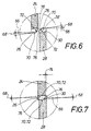
- FIG. 6 shows a section of the counter element on an enlarged scale 28 and a section of the spring plate 24 in the release position in which the Spring plate 24 laterally, tooth-axially with respect to the seat-fixed counter element 28 is adjusted.
- the teeth 26 of the spring element 24 and the counter teeth 30 of the seat-fixed counter element 28 close with the common tooth axis, the is illustrated in FIG. 7 by the thin dash-dotted line 66 or that in FIG. 6 by one each associated with the spring plate 24 and one with the counter element 28 thin dash-dotted line 66 is indicated, an acute angle 68.
- there the teeth of the teeth 26 and the teeth of the counter teeth 30 are of this type formed that the tooth heads 70 and the tooth feet 72 each parallel to each other are.
- Figure 7 illustrates that the teeth 26 of the spring plate 24 and the teeth 30th of the seat-fixed counter element 28 are dimensioned in terms of diameter, that the spring element 24 in the unused original condition against the seat Counter element 28, laterally tooth-axially offset by a defined dimension 74. This will automatically adjust the spring plate 24 relative to Counter element 28 causes wear after a long life.
- the teeth 26 of the spring plate 24 and the counter teeth 30 of the seat-fixed Counter element 28 are in the transition between their in the release position tooth flanks 76 facing one another and the tooth tips 70 rounded (see FIG. Figure 6). These roundings are indicated by the arrows 78.
Landscapes
- Engineering & Computer Science (AREA)
- Aviation & Aerospace Engineering (AREA)
- Transportation (AREA)
- Mechanical Engineering (AREA)
- Chairs For Special Purposes, Such As Reclining Chairs (AREA)
- Seats For Vehicles (AREA)
Abstract
Description
- Figur 1
- eine Seitenansicht eines schematisch dargestellten Fahrzeugsitzes,
- Figur 2
- abschnittweise in einer Schnittdarstellung eine erste Ausbildung der Verstelleinrichtung,
- Figur 3
- in einer der Figur 2 ähnlichen Schnittdarstellung abschnittweise eine zweite Ausbildung der Verstell-Einrichtung,
- Figur 4
- eine Ansicht des Federbleches und des Gegenelementes, die abschnittweise gezeichnet sind, in Blickrichtung der Pfeile IV-IV in Figur 3, wobei der Schwenkhebel der Verstelleinrichtung mit dünnen doppelt strichpunktierten Linien angedeutet ist,
- Figur 5
- eine den Figuren 2 und 3 ähnliche Schnittdarstellung einer dritten, abschnittweise gezeichneten Ausbildung der Verstell-Einrichtung mit einem Schiebehebel,
- Figur 6
- in einem vergrößerten Maßstab das Detail VI in Figur 2 - in der Freigabestellung des Federbleches -, und
- Figur 7
- eine der Figur 6 ähnliche Darstellung, wobei das Federblech jedoch die Raststellung einnimmt.
Claims (10)
- Einrichtung zur Neigungsverstellung einer Rückenlehne (14) in Bezug auf eine Sitzplatte (12) eines Sitzes, insbesondere eines Fahrzeugsitzes (10),
dadurch gekennzeichnet, daß an der Rückenlehne (14) oder an der Sitzplatte (12) ein mit einer Zahnung (26) ausgebildetes Federblech (24) und an der Sitzplatte (12) oder an der Rückenlehne (14) ein mit einer Gegenzahnung (30) ausgebildetes sitzfestes Gegenelement (28) angebracht ist, wobei die Zahnung (26) des Federbleches (24) in der normalen Arretierstellung in die Gegenzahnung (30) des Gegenelementes (28) spielfrei eingreift, und daß dem Federblech (24) eine zwischen einer Raststellung und einer Freigabestellung verstellbare Betätigungseinrichtung (36) zugeordnet ist, mit der die Zahnung (26) des Federbleches (24) in der Freigabestellung aus der Gegenzahnung (30) des Gegenelementes (28) seitlich, zahnaxial ausrastbar ist. - Einrichtung nach Anspruch 1,
dadurch gekennzeichnet, daß das Gegenelement (28), das Federblech (24) und die dem Federblech (24) zugeordnete Betätigungseinrichtung (36) an einem Sitzbeschlag (16) angebracht sind. - Einrichtung nach Anspruch 2,
dadurch gekennzeichnet, daß das Federblech (24) mit einem Befestigungsabschnitt (34) am Sitzbeschlag (16) befestigt ist. - Einrichtung nach Anspruch 2,
dadurch gekennzeichnet, daß das Gegenelement (28) am Sitzbeschlag (16) befestigt oder ein integrales Bestandteil desselben ist. - Einrichtung nach einem der Ansprüche 2 bis 4,
dadurch gekennzeichnet, daß die Betätigungseinrichtung (36) eine am Sitzbeschlag (16) gelagerte Achse (38) mit einem am Federblech (24) anliegenden Verstellnocken (40) aufweist. - Einrichtung nach einem der Ansprüche 1 bis 4,
dadurch gekennzeichnet, daß die Betätigungseinrichtung (36) einen Schwenkhebel (46) mit Preßelementen (48) und daß das Federblech (24) Keilrippen (52) aufweist, wobei die Preßelemente (48) und die Keilrippen (52) entlang deckungsgleichen Teilkreisen (54) vorgesehen sind. - Einrichtung nach einem der Ansprüche 1 bis 4,
dadurch gekennzeichnet, daß das Federblech (24) einen Keil (64) und daß die Betätigungseinrichtung (36) einen Schiebehebel (58) mit einem Preßelement (62) aufweist, der entlang des Keiles (64) verschiebbar ist. - Einrichtung insbesondere nach einem der Ansprüche 1 bis 7,
dadurch gekennzeichnet, daß die Zahnung (26) und die Gegenzahnung (30) mit der gemeinsamen Zahnungsachse (66) einen spitzen Winkel (68) einschließen. - Einrichtung nach Anspruch 8,
dadurch gekennzeichnet, daß der spitze Winkel (68) in Federblech-Öffnungsrichtung (Pfeil 42) derartig erweitert ist, daß sich in der Raststellung eine Selbsthemmung ergibt. - Einrichtung insbesondere nach einem der Ansprüche 1 bis 9,
dadurch gekennzeichnet, daß die Zahnung (26) und die Gegenzahnung (30) im Übergang zwischen ihren in der Freigabestellung einander zugewandten Zahnflanken (76) und den Zahnköpfen (70) abgerundet (Pfeil 78) sind.
Applications Claiming Priority (2)
| Application Number | Priority Date | Filing Date | Title |
|---|---|---|---|
| DE10039042A DE10039042C2 (de) | 2000-08-10 | 2000-08-10 | Einrichtung zur Neigungsverstellung einer Rückenlehne |
| DE10039042 | 2000-08-10 |
Publications (2)
| Publication Number | Publication Date |
|---|---|
| EP1180447A1 true EP1180447A1 (de) | 2002-02-20 |
| EP1180447B1 EP1180447B1 (de) | 2005-04-27 |
Family
ID=7651970
Family Applications (1)
| Application Number | Title | Priority Date | Filing Date |
|---|---|---|---|
| EP01118477A Expired - Lifetime EP1180447B1 (de) | 2000-08-10 | 2001-08-01 | Einrichtung zur Neigungsverstellung einer Rückenlehne |
Country Status (3)
| Country | Link |
|---|---|
| US (1) | US20020089226A1 (de) |
| EP (1) | EP1180447B1 (de) |
| DE (1) | DE10039042C2 (de) |
Families Citing this family (1)
| Publication number | Priority date | Publication date | Assignee | Title |
|---|---|---|---|---|
| JP4159477B2 (ja) | 2002-03-22 | 2008-10-01 | ミルスコ マニュファクシャーリング、ア ユニット オブ ジェーソン インコポレーテッド | 座席用サスペンション |
Citations (7)
| Publication number | Priority date | Publication date | Assignee | Title |
|---|---|---|---|---|
| US2660226A (en) * | 1951-06-13 | 1953-11-24 | Milsco Mfg Company | Seat back rest support |
| US3328079A (en) * | 1965-11-24 | 1967-06-27 | Young Spring & Wire Corp | Reclining seat |
| DE1289268B (de) * | 1966-10-28 | 1969-02-13 | Keiper Recaro Gmbh Co | Vorrichtung zum AEndern der Neigung und zum Verriegeln einer schwenkbaren Rueckenlehne eines Sitzes |
| DE6908021U (de) * | 1969-02-28 | 1969-06-19 | Isringhausen Fa Geb | Fahrzeugsitz mit rueckenlehnenverstellung |
| DE2660395B1 (de) * | 1976-03-09 | 1980-08-14 | Keiper Automobiltechnik Gmbh | Drehbeschlag zum Verstellen des Neigungswinkels von Rueckenlehnen an Sitzen |
| EP0425237A2 (de) * | 1989-10-23 | 1991-05-02 | Fuji Kiko Company Limited | Neigungsverstellvorrichtung für einen Kraftfahrzeugsitz |
| DE4441159A1 (de) * | 1993-11-19 | 1995-05-24 | Aisin Seiki | Sitzverstellvorrichtung |
Family Cites Families (1)
| Publication number | Priority date | Publication date | Assignee | Title |
|---|---|---|---|---|
| DE8000749U1 (de) * | 1980-01-14 | 1980-04-17 | Franz Kiel Gmbh, 8860 Noerdlingen | Vorrichtung zum verstellen von rueckenlehnen an kraftfahrzeugsitzen |
-
2000
- 2000-08-10 DE DE10039042A patent/DE10039042C2/de not_active Expired - Fee Related
-
2001
- 2001-08-01 EP EP01118477A patent/EP1180447B1/de not_active Expired - Lifetime
- 2001-08-08 US US09/924,618 patent/US20020089226A1/en not_active Abandoned
Patent Citations (7)
| Publication number | Priority date | Publication date | Assignee | Title |
|---|---|---|---|---|
| US2660226A (en) * | 1951-06-13 | 1953-11-24 | Milsco Mfg Company | Seat back rest support |
| US3328079A (en) * | 1965-11-24 | 1967-06-27 | Young Spring & Wire Corp | Reclining seat |
| DE1289268B (de) * | 1966-10-28 | 1969-02-13 | Keiper Recaro Gmbh Co | Vorrichtung zum AEndern der Neigung und zum Verriegeln einer schwenkbaren Rueckenlehne eines Sitzes |
| DE6908021U (de) * | 1969-02-28 | 1969-06-19 | Isringhausen Fa Geb | Fahrzeugsitz mit rueckenlehnenverstellung |
| DE2660395B1 (de) * | 1976-03-09 | 1980-08-14 | Keiper Automobiltechnik Gmbh | Drehbeschlag zum Verstellen des Neigungswinkels von Rueckenlehnen an Sitzen |
| EP0425237A2 (de) * | 1989-10-23 | 1991-05-02 | Fuji Kiko Company Limited | Neigungsverstellvorrichtung für einen Kraftfahrzeugsitz |
| DE4441159A1 (de) * | 1993-11-19 | 1995-05-24 | Aisin Seiki | Sitzverstellvorrichtung |
Also Published As
| Publication number | Publication date |
|---|---|
| DE10039042C2 (de) | 2002-10-31 |
| EP1180447B1 (de) | 2005-04-27 |
| US20020089226A1 (en) | 2002-07-11 |
| DE10039042A1 (de) | 2002-02-28 |
Similar Documents
| Publication | Publication Date | Title |
|---|---|---|
| DE10164035B4 (de) | Fahrzeugsitz mit einem Gelenkbeschlag | |
| DE102017110246A1 (de) | Schwenkbeschlag und Möbel | |
| DE10107237B4 (de) | Verstelleinrichtung für Kraftfahrzeugsitze | |
| DE102008061037B3 (de) | Fahrzeugsitz mit Klinkenanordnung | |
| DE69500927T2 (de) | Feststellmechanismus für eine verstellbare lenksäule eines fahrzeugs | |
| DE4400910C2 (de) | Selbstsperrende Schrittmechanik für eine Verstellvorrichtung eines Kraftfahrzeugsitzes | |
| DE102015101829A1 (de) | Spannklaue zur Anbringung an einer Gleitschiene eines Operationstisches | |
| EP1725429A1 (de) | Vorrichtung zur winkelverstellung einer um eine drehachse drehbar vorgesehenen komponente, insbesondere einer armlehne in einem fahrzeug | |
| WO2015106852A1 (de) | Schwenkgelenk und möbelstück mit einem solchen | |
| DE102009031702A1 (de) | Vorrichtung zum Verstellen eines Bauteils, insbesondere einer Armlehne für ein Kraftfahrzeug | |
| DE102008030160B4 (de) | Armlehne zur Anordnung in einem Fahrzeug | |
| DE602006000338T2 (de) | Antriebsvorrichtung eines elektischen Schaltgerätes mit Schaltsperre | |
| DE3515455A1 (de) | Rueckwaertsneigungswinkel-einstelleinrichtung | |
| DE10329921A1 (de) | Kindersitz | |
| DE202014100778U1 (de) | Betätigungsvorrichtung für eine Feststellbremse | |
| WO2001044008A1 (de) | Vorrichtung zum verstellen der neigung einer sitzplatte eines fahrzeugsitzes | |
| DE102009043140B3 (de) | Kraftfahrzeugsitz | |
| DE202006019497U1 (de) | Schwenkbeschlag | |
| DE10039042C2 (de) | Einrichtung zur Neigungsverstellung einer Rückenlehne | |
| DE10240017B4 (de) | Vorrichtung zum Verriegeln eines Beschlags eines Fahrzeugsitzes | |
| EP1584265B1 (de) | Rastbeschlag | |
| EP2034109A2 (de) | Sicherungseinrichtung | |
| DE10138116C1 (de) | Verstellbares Pedalwerk mit Sicherungselement | |
| DE2322207C2 (de) | Gelenkbeschlag für Sitze mit verstellbarer Rückenlehne, insbesondere für Kraftfahrzeugsitze | |
| DE102012104101B4 (de) | Radialverstellung mit Arretierfunktion |
Legal Events
| Date | Code | Title | Description |
|---|---|---|---|
| PUAI | Public reference made under article 153(3) epc to a published international application that has entered the european phase |
Free format text: ORIGINAL CODE: 0009012 |
|
| AK | Designated contracting states |
Kind code of ref document: A1 Designated state(s): DE FR GB IT TR Kind code of ref document: A1 Designated state(s): AT BE CH CY DE DK ES FI FR GB GR IE IT LI LU MC NL PT SE TR |
|
| AX | Request for extension of the european patent |
Free format text: AL;LT;LV;MK;RO;SI |
|
| 17P | Request for examination filed |
Effective date: 20011215 |
|
| AKX | Designation fees paid |
Free format text: DE FR GB IT TR |
|
| 17Q | First examination report despatched |
Effective date: 20040701 |
|
| GRAP | Despatch of communication of intention to grant a patent |
Free format text: ORIGINAL CODE: EPIDOSNIGR1 |
|
| GRAS | Grant fee paid |
Free format text: ORIGINAL CODE: EPIDOSNIGR3 |
|
| GRAA | (expected) grant |
Free format text: ORIGINAL CODE: 0009210 |
|
| RBV | Designated contracting states (corrected) |
Designated state(s): FR GB IT TR |
|
| AK | Designated contracting states |
Kind code of ref document: B1 Designated state(s): FR GB IT TR |
|
| REG | Reference to a national code |
Ref country code: GB Ref legal event code: FG4D Free format text: NOT ENGLISH |
|
| REG | Reference to a national code |
Ref country code: IE Ref legal event code: FG4D Free format text: LANGUAGE OF EP DOCUMENT: GERMAN |
|
| REG | Reference to a national code |
Ref country code: DE Ref legal event code: 8566 |
|
| GBT | Gb: translation of ep patent filed (gb section 77(6)(a)/1977) |
Effective date: 20050726 |
|
| ET | Fr: translation filed | ||
| PLBE | No opposition filed within time limit |
Free format text: ORIGINAL CODE: 0009261 |
|
| STAA | Information on the status of an ep patent application or granted ep patent |
Free format text: STATUS: NO OPPOSITION FILED WITHIN TIME LIMIT |
|
| 26N | No opposition filed |
Effective date: 20060130 |
|
| REG | Reference to a national code |
Ref country code: FR Ref legal event code: PLFP Year of fee payment: 15 |
|
| PGFP | Annual fee paid to national office [announced via postgrant information from national office to epo] |
Ref country code: GB Payment date: 20150824 Year of fee payment: 15 |
|
| PGFP | Annual fee paid to national office [announced via postgrant information from national office to epo] |
Ref country code: FR Payment date: 20150824 Year of fee payment: 15 |
|
| GBPC | Gb: european patent ceased through non-payment of renewal fee |
Effective date: 20160801 |
|
| REG | Reference to a national code |
Ref country code: FR Ref legal event code: ST Effective date: 20170428 |
|
| PG25 | Lapsed in a contracting state [announced via postgrant information from national office to epo] |
Ref country code: GB Free format text: LAPSE BECAUSE OF NON-PAYMENT OF DUE FEES Effective date: 20160801 Ref country code: FR Free format text: LAPSE BECAUSE OF NON-PAYMENT OF DUE FEES Effective date: 20160831 |
|
| PGFP | Annual fee paid to national office [announced via postgrant information from national office to epo] |
Ref country code: TR Payment date: 20190826 Year of fee payment: 19 Ref country code: IT Payment date: 20190821 Year of fee payment: 19 |
|
| PG25 | Lapsed in a contracting state [announced via postgrant information from national office to epo] |
Ref country code: IT Free format text: LAPSE BECAUSE OF NON-PAYMENT OF DUE FEES Effective date: 20200801 |
|
| PG25 | Lapsed in a contracting state [announced via postgrant information from national office to epo] |
Ref country code: TR Free format text: LAPSE BECAUSE OF NON-PAYMENT OF DUE FEES Effective date: 20200801 |