EP1179902B1 - Transmitter, receiver, and method of data transmission - Google Patents
Transmitter, receiver, and method of data transmission Download PDFInfo
- Publication number
- EP1179902B1 EP1179902B1 EP01912256A EP01912256A EP1179902B1 EP 1179902 B1 EP1179902 B1 EP 1179902B1 EP 01912256 A EP01912256 A EP 01912256A EP 01912256 A EP01912256 A EP 01912256A EP 1179902 B1 EP1179902 B1 EP 1179902B1
- Authority
- EP
- European Patent Office
- Prior art keywords
- signal
- band
- transmitting
- section
- transmitting apparatus
- Prior art date
- Legal status (The legal status is an assumption and is not a legal conclusion. Google has not performed a legal analysis and makes no representation as to the accuracy of the status listed.)
- Expired - Lifetime
Links
Images


Classifications
-
- H—ELECTRICITY
- H04—ELECTRIC COMMUNICATION TECHNIQUE
- H04B—TRANSMISSION
- H04B7/00—Radio transmission systems, i.e. using radiation field
-
- H—ELECTRICITY
- H04—ELECTRIC COMMUNICATION TECHNIQUE
- H04L—TRANSMISSION OF DIGITAL INFORMATION, e.g. TELEGRAPHIC COMMUNICATION
- H04L5/00—Arrangements affording multiple use of the transmission path
- H04L5/02—Channels characterised by the type of signal
- H04L5/023—Multiplexing of multicarrier modulation signals
-
- H—ELECTRICITY
- H04—ELECTRIC COMMUNICATION TECHNIQUE
- H04B—TRANSMISSION
- H04B1/00—Details of transmission systems, not covered by a single one of groups H04B3/00 - H04B13/00; Details of transmission systems not characterised by the medium used for transmission
- H04B1/69—Spread spectrum techniques
- H04B1/707—Spread spectrum techniques using direct sequence modulation
-
- H—ELECTRICITY
- H04—ELECTRIC COMMUNICATION TECHNIQUE
- H04L—TRANSMISSION OF DIGITAL INFORMATION, e.g. TELEGRAPHIC COMMUNICATION
- H04L5/00—Arrangements affording multiple use of the transmission path
- H04L5/02—Channels characterised by the type of signal
- H04L5/06—Channels characterised by the type of signal the signals being represented by different frequencies
Definitions
- the present invention relates to a transmitting apparatus, receiving apparatus, and data transmission method for use in a communication terminal apparatus and base station apparatus of a mobile communication system using the OFDM (Orthogonal Frequency Division Multiplex) modulation method.
- OFDM Orthogonal Frequency Division Multiplex
- FIG.1 is a block diagram showing the configuration of a conventional transmitting apparatus and receiving apparatus.
- the transmitting apparatus and receiving apparatus in FIG.1 are provided, respectively, in a base station apparatus and communication terminal apparatus in an OFDM modulation mobile communication system.
- the transmitting apparatus 10 mainly consists of an S/P (Serial/Parallel) conversion section 11, an IFFT (Inverse Fast Fourier Transform) section 12, and a modulation section 13.
- the receiving apparatus 20 mainly consists of a reception filter section 21, an FFT (Fast Fourier Transform) section 22, and a P/S (Parallel/Serial) conversion section 23.
- transmit data undergoes parallel conversion to N (where N is a natural number) subcarriers by the S/P conversion section 11 in the transmitting apparatus 10, then undergoes an inverse Fourier transform together with 2M (where M is a natural number) 0 data units by the IFFT section 12, and after being modulated by the modulation section 13, is transmitted as a radio signal from an antenna.
- a radio signal transmitted from the transmitting apparatus 10 is received by the antenna of the receiving apparatus 20, and a signal of a predetermined frequency is passed by the reception filter section 21, is demodulated by undergoing a Fourier transform by the FFT section 22, and is converted to serial form by the P/S conversion section 23. By this means, receive data is obtained.
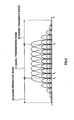
- FIG.2 is a frequency spectrum diagram for the conventional OFDM modulation method.
- a signal transmission band 51 is provided in which there is a plurality of carrier frequency signals f1 to fn.
- adjacent carrier frequency signals are arranged so that-with f1 and f2, for example-the 0 level point of one carrier frequency signal f2 overlaps the peak level point of the other carrier frequency signal f1 on the same frequency axis.
- the frequency intervals at which a peak level point and 0 level point overlap are equal intervals, being a frequency interval which is the inverse of the symbol rate. For example, with a symbol rate of 1 ⁇ sec, the frequency interval is every 1 MHz.
- guard frequency bands 52 and 53 are not used for signal transmission presents a problem in that spectrum efficiency is reduced proportionately.
- EP 0 886 408 discloses an orthogonal frequency division multiplex (OFDM) modulator in a multicarrier system including an IFFT section for conducting inverse fast fourier (?) transform (IFFT) processing to modulate the input data train (?) into a large number of sub-carriers.
- OFDM orthogonal frequency division multiplex
- This objective is achieved by superimposing broadcast information, peak suppression signals, and so forth, in the guard frequency bands.
- FIG.3 is a block diagram showing the configuration of a transmitting apparatus and receiving apparatus according to Embodiment 1 of the present invention.
- the transmitting apparatus and receiving apparatus in FIG.3 are provided respectively in a base station apparatus and communication terminal apparatus in an OFDM modulation mobile communication system.
- a description is given of radio communication between a transmitting apparatus provided in a base station apparatus and a receiving apparatus provided in a communication terminal apparatus.
- the transmitting apparatus 100 mainly consists of an S/P conversion section 101, IFFT section 102, spreading section 103, band limiting filter section 104, adding section 105, and modulation section 106.
- the S/P conversion section 101 performs parallel conversion of serial transmit data to N (where N is a natural number) subcarriers.
- the IFFT section 102 performs an inverse Fourier transform on N (where N is a natural number) subcarriers together with 2M (where M is a natural number) 0 data units for forming guard frequency bands. As a result of this inverse Fourier transform, an OFDM modulation signal is output.
- the spreading section 103 multiplies broadcast information by a spreading code.
- the band limiting filter section 104 performs limitation so that the spread broadcast information band becomes a guard frequency band. By means of this band limitation, broadcast information is superimposed on a guard frequency band.
- broadcast information for which the band is limited to a guard frequency band is referred to as a "band limited signal”.
- the adding section 105 adds together the OFDM modulation signal output from the IFFT section 102 and the band limited signal output from the band limiting filter section 104.
- the modulation section 106 modulates the output signal from the adding section 105 and transmits it as a radio signal from the antenna.
- the receiving apparatus 150 mainly consists of a reception filter section 151, an FFT section 152, a P/S conversion section 153, a reception filter section 154, a demodulation section 155, a despreading section 156, and a rake reception section 157.
- Reception filter section 151 passes only signals in the signal transmission band among received signals.
- the FFT section 152 demodulates a signal that has passed through reception filter section 151 by performing a Fourier transform.
- the P/S conversion section 153 performs serial conversion of the output signal from the FFT section 152 to obtain receive data.
- Reception filter section 154 passes only signals in a guard frequency band among received signals.
- the demodulation section 155 demodulates a signal that has passed through reception filter section 154.
- the despreading section 156 multiplies the output signal from the demodulation section 155 by the same spreading code as used by the spreading section 103.
- the rake reception section 157 performs rake reception of the output signal from the despreading section 156 to obtain broadcast information.
- Broadcast information is spread by the spreading section 103, and is band-limited by the band limiting filter section 104 so as to become a guard frequency band.
- the OFDM modulation signal output from the IFFT section 102 and the band limited signal output from the band limiting filter section 104 are added, then modulated by the modulation section 106, and transmitted from the antenna.
- a radio signal transmitted from the transmitting apparatus 100 is received by the antenna of the receiving apparatus 150, and is output to reception filter section 151 and reception filter section 154.
- a signal in the signal transmission band that has passed through reception filter section 151 is demodulated by undergoing a Fourier transform by the FFT section 152, and is converted to serial form by the P/S conversion section 153. By this means, receive data is obtained.
- a signal in a guard frequency band that has passed through reception filter section 154 is demodulated by the demodulation section 155 and despread by the despreading section 156, and undergoes rake reception by the rake reception section 157.
- broadcast information is obtained.
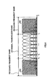
- FIG.4 is a frequency spectrum diagram for the OFDM method of this embodiment.
- a signal transmission band 201 is provided in which there is a plurality of carrier frequency signals f1 to fn.
- guard frequency bands 202 and 203 are provided on either side of the signal transmission band 201.
- broadcast information 204 and 205 is band-limited and superimposed on guard frequency bands 202 and 203.
- OFDM modulation signals and band limited signals comprising band limited broadcast information can be transmitted from the same antenna on the transmitting side, and received by the same antenna on the receiving side, fading correlation is high, and the SIR (Signal to Interference Ratio) is not so poor, with the result that data can be transmitted with a certain level of quality.
- band limited signal multiplexing method and modulation method Although there are no restrictions on the band limited signal multiplexing method and modulation method, if the CDMA method is used as described above, band limited signals are resistant to interference and their quality is improved.
- the signals superimposed on guard frequency bands are not limited to broadcast information, and may comprise any kind of information. For example, if a peak suppression signal is superimposed instead of broadcast information, peak suppression can be performed.
- FIG.5 is a block diagram showing the configuration of a transmitting apparatus and receiving apparatus according to Embodiment 2 of the present invention.
- the parts of the transmitting apparatus and receiving apparatus in FIG. 5 identical to those in FIG. 3 are assigned the same codes as in FIG.3 and their detailed explanations are omitted.
- the configuration of the transmitting apparatus 300 shown in FIG.5 features the addition of a spectrum processing section 301 to the transmitting apparatus 100 shown in FIG.3 .
- the spectrum processing section 301 performs processing of the frequency spectrum of band limited signals output from the band limiting filter section 104 so that portions are larger the nearer they are to the signal transmission band (hereinafter referred to as "spectrum coloring").
- the adding section 105 adds together an OFDM modulation signal that has undergone spectrum coloring by the spectrum processing section 301 and a band limited signal output from the band limiting filter section 104.
- the configuration of the receiving apparatus 350 shown in FIG.5 features the addition of a spectrum processing section 351 to the receiving apparatus 150 shown in FIG.3 .
- Spectrum processing section 351 performs the opposite of the processing performed by spectrum processing section 301 on a band limited signal received via reception filter section 154 (hereinafter referred to as "spectrum decoloring"). By means of this spectrum decoloring, a received band limited signal returns to its original flat spectrum.
- FIG.6 is a frequency spectrum diagram for the OFDM method of this embodiment.
- guard frequency bands 202 and 203 interference is proportionately greater nearer the signal transmission band 201.
- the frequency spectra of broadcast information 401 and 402 are processed so that portions are larger the nearer they are to the signal transmission band before transmission.
- the opposite processing is carried out when performing demodulation.
- FIG.7 is a block diagram showing the configuration of a transmitting apparatus and receiving apparatus according to Embodiment 3 of the present invention.
- the parts of the transmitting apparatus and receiving apparatus in FIG. 7 identical to those in FIG. 3 are assigned the same codes as in FIG.3 and their detailed explanations are omitted.
- the configuration of the transmitting apparatus 500 shown in FIG.7 features the addition of an S/P conversion section 501 and a plurality of frequency shift sections 502 to the transmitting apparatus 100 shown in FIG.3 , and has a plurality of spreading sections 103 and band limiting filter sections 104.
- the S/P conversion section 501 converts broadcast information to parallel form.
- Each of spreading sections 103-1 to 103-n (where n is a natural number not less than 2) multiplies the respective broadcast information converted to parallel from by a spreading code.
- Each of band limiting filter sections 104-1 to 104-n performs limitation so that the band of broadcast information output from the corresponding spreading section 103-1 to 103-n becomes part of a guard frequency band.
- Frequency shift sections 502-1 to 502-n shift the frequency of band limited signals output from corresponding band limiting filter sections 104-1 to 104-n by a predetermined amount. This shift is performed so that no band limited signal overlaps a band in which another band limited signal is superimposed.
- the adding section 105 adds together the OFDM modulation signal output from the IFFT section 102 and the band limited signal output from each of frequency shift sections 502-1 to 502-n.
- the configuration of the receiving apparatus 550 shown in FIG.7 features the addition of a P/S conversion section 551 to the receiving apparatus 150 shown in FIG.3 , and has a plurality of reception filter sections 154, demodulation sections 155, despreading sections 156, and rake reception sections 157.
- Reception filter sections 154-1 to 154-n pass only signals of part of the guard frequency bands among received signals.
- Each of demodulation sections 155-1 to 155-n demodulates the signal that has passed through the corresponding reception filter section 154-1 to 154-n.
- Each of despreading sections 156-1 to 156-n multiplies the output signal of the corresponding demodulation section 155-1 to 155-n by the same spreading code as used by spreading sections 103-1 to 103n.
- Each of rake reception sections 157-1 to 157-n performs rake reception of the output signal of the corresponding despreading section 156-1 to 156-n.
- the P/S conversion section 551 converts the output signals of each of rake reception sections 157-1 to 157-n to serial form to obtain broadcast information.
- FIG.8 is a first frequency spectrum diagram for the OFDM method of this embodiment. As shown in FIG.8 , by shifting the frequencies of broadcast information band limited signals 601 to 606 that have been converted to parallel form so that they do not mutually overlap, it is possible to perform multicarrier superimposition in guard frequency bands 202 and 203.
- the power of band limited signals 601 to 606 superimposed on guard frequency bands 202 and 203 may be processed in the transmitting apparatus so that the spectrum is proportionately greater for those of band limited signals 701 to 706 nearer the signal transmission band 201 before transmission, and the opposite of the transmitting apparatus processing may be performed in the receiving apparatus.
- FIG.10 is a block diagram showing the configuration of a transmitting apparatus and receiving apparatus according to Embodiment 4 of the present invention.
- the parts of the transmitting apparatus and receiving apparatus in FIG.10 identical to those in FIG.7 are assigned the same codes as in FIG.7 and their detailed explanations are omitted.
- the configuration of the transmitting apparatus 800 shown in FIG.10 features the addition of a buffer section 801 and peak suppression signal generating section 802 to the transmitting apparatus 500 shown in FIG.7 , and the elimination of spreading section 103-n.
- the buffer section 801 temporarily stores an OFDM modulation signal output from the IFFT section 102.
- the peak suppression signal generating section 802 generates a peak suppression signal according to the composite amplitude (composite peak) of OFDM modulation signals stored in the buffer section 801. This peak suppression signal lowers this composite amplitude to a predetermined level.
- Band limiting filter section 104-n limits the band of the peak suppression signal so that it becomes part of a guard frequency band.
- Frequency shift section 502-n shifts the frequency of the band limited signal output from band limiting filter section 104-n by a predetermined amount.
- the configuration of the receiving apparatus 850 shown in FIG.10 features the elimination of reception filter section 154-n, demodulation section 155-n, despreading section 156-n, and rake reception section 157-n from the transmitting apparatus 500 shown in FIG.7 .
- the P/S conversion section 551 converts the output signals of each of rake reception sections 157-1 to 157-(n-1) to serial form to obtain broadcast information.
- the use of a peak suppression signal does not lower spectrum efficiency as has been the case heretofore.
- the quality of a subcarrier near the signal transmission band 201 is poor because interference from OFDM modulation signals is great.
- a peak suppression signal itself does not carry information, demodulation is not necessary, and there is no problem even if quality is poor. Therefore, by superimposing a peak suppression signal on a band near the signal transmission band 201, it is possible to superimpose broadcast information on a band in which there is little interference, and to improve the quality of that broadcast information.
- a guard frequency band can also be used for signal transmission by superimposing broadcast information, a peak suppression signal, or the like, on a guard frequency band, thereby enabling spectrum efficiency to be improved.
- the present invention is suitable for use in a communication terminal apparatus or base station apparatus in a mobile communication system using the OFDM modulation method.
Applications Claiming Priority (3)
| Application Number | Priority Date | Filing Date | Title |
|---|---|---|---|
| JP2000072818A JP4323669B2 (ja) | 2000-03-15 | 2000-03-15 | データ伝送装置及びデータ伝送方法 |
| JP2000072818 | 2000-03-15 | ||
| PCT/JP2001/001897 WO2001069825A1 (fr) | 2000-03-15 | 2001-03-12 | Émetteur, récepteur et technique de transmission de données |
Publications (3)
| Publication Number | Publication Date |
|---|---|
| EP1179902A1 EP1179902A1 (en) | 2002-02-13 |
| EP1179902A4 EP1179902A4 (en) | 2006-04-05 |
| EP1179902B1 true EP1179902B1 (en) | 2008-07-23 |
Family
ID=18591168
Family Applications (1)
| Application Number | Title | Priority Date | Filing Date |
|---|---|---|---|
| EP01912256A Expired - Lifetime EP1179902B1 (en) | 2000-03-15 | 2001-03-12 | Transmitter, receiver, and method of data transmission |
Country Status (8)
| Country | Link |
|---|---|
| US (1) | US7012949B2 (ja) |
| EP (1) | EP1179902B1 (ja) |
| JP (1) | JP4323669B2 (ja) |
| KR (1) | KR100572435B1 (ja) |
| CN (1) | CN100456657C (ja) |
| AU (1) | AU4109201A (ja) |
| DE (1) | DE60134920D1 (ja) |
| WO (1) | WO2001069825A1 (ja) |
Families Citing this family (32)
| Publication number | Priority date | Publication date | Assignee | Title |
|---|---|---|---|---|
| JP2003309533A (ja) * | 2002-04-17 | 2003-10-31 | Matsushita Electric Ind Co Ltd | 無線送信装置、無線受信装置及びその方法 |
| KR100824367B1 (ko) * | 2002-05-24 | 2008-04-22 | 삼성전자주식회사 | Ofdm 송신기 및 그의 신호처리방법 |
| KR100548312B1 (ko) * | 2002-06-20 | 2006-02-02 | 엘지전자 주식회사 | 다중 입출력 이동 통신 시스템에서의 신호 처리 방법 |
| US7251301B2 (en) * | 2002-08-14 | 2007-07-31 | Industrial Technology Research Institute | Methods and systems for providing a noise signal |
| US7418040B2 (en) * | 2003-05-30 | 2008-08-26 | Motorola, Inc. | Method and apparatus for determining a timing offset for processing a multi-carrier signal |
| US7532565B2 (en) | 2004-05-07 | 2009-05-12 | Texas Instruments Incorporated | Mapping data tones onto guard tones for a multi-band OFDM system |
| EP1608100A1 (en) * | 2004-06-17 | 2005-12-21 | Mitsubishi Electric Information Technology Centre Europe B.V. | Method for transmitting TDD frames with increased data payload |
| US7852746B2 (en) * | 2004-08-25 | 2010-12-14 | Qualcomm Incorporated | Transmission of signaling in an OFDM-based system |
| DE202005022046U1 (de) * | 2004-10-29 | 2012-08-24 | Sharp Kabushiki Kaisha | Funksender und Funkempfänger |
| EP2555464B1 (en) | 2005-01-18 | 2019-03-06 | Sharp Kabushiki Kaisha | Wireless communication apparatus and wireless communication method |
| US7894818B2 (en) * | 2005-06-15 | 2011-02-22 | Samsung Electronics Co., Ltd. | Apparatus and method for multiplexing broadcast and unicast traffic in a multi-carrier wireless network |
| US20070002724A1 (en) * | 2005-06-15 | 2007-01-04 | Samsung Electronics Co., Ltd. | Apparatus and method for broadcast superposition and cancellation in a multi-carrier wireless network |
| US7944995B2 (en) * | 2005-11-14 | 2011-05-17 | Telefonaktiebolaget Lm Ericsson (Publ) | Variable bandwidth receiver |
| JP4946159B2 (ja) * | 2006-05-09 | 2012-06-06 | 富士通株式会社 | 無線送信方法及び無線受信方法並びに無線送信装置及び無線受信装置 |
| US8169955B2 (en) * | 2006-06-19 | 2012-05-01 | Atc Technologies, Llc | Systems and methods for orthogonal frequency division multiple access (OFDMA) communications over satellite links |
| CN101106435B (zh) * | 2006-07-10 | 2011-08-03 | 华为技术有限公司 | 一种多对线共同传输的方法及发送端和接收端 |
| JP4827671B2 (ja) * | 2006-09-20 | 2011-11-30 | パナソニック株式会社 | 送信装置およびピーク抑圧方法 |
| US9201854B1 (en) * | 2006-10-25 | 2015-12-01 | Hewlett-Packard Development Company, L.P. | Methods and systems for creating, interacting with, and utilizing a superactive document |
| JP5036809B2 (ja) * | 2007-03-28 | 2012-09-26 | パナソニック株式会社 | 無線通信装置および緊急信号送信方法 |
| JP5035351B2 (ja) * | 2007-11-28 | 2012-09-26 | 富士通株式会社 | 無線送信装置、無線受信装置、無線送受信システム、及びこれらの方法 |
| US8432939B2 (en) * | 2008-05-15 | 2013-04-30 | Qualcomm Incorporated | Using guard carriers for extra channels |
| KR101496896B1 (ko) | 2009-02-16 | 2015-02-27 | 삼성전자주식회사 | 대역 확장성을 지원하는 셀룰러 무선통신시스템에서 보호대역이 구성된 하향링크 신호의 송수신 방법 및 장치 |
| CN101695004B (zh) * | 2009-10-22 | 2013-02-13 | 南京莱斯信息技术股份有限公司 | 一种电台信号的分离系统 |
| JP5212402B2 (ja) * | 2010-02-24 | 2013-06-19 | 住友電気工業株式会社 | ピーク電力抑制回路とこの回路を有する通信装置 |
| US9042938B2 (en) | 2012-12-27 | 2015-05-26 | Google Technology Holdings LLC | Method and apparatus for device-to-device communication |
| US9185697B2 (en) | 2012-12-27 | 2015-11-10 | Google Technology Holdings LLC | Method and apparatus for device-to-device communication |
| US9143291B2 (en) | 2012-12-27 | 2015-09-22 | Google Technology Holdings LLC | Method and apparatus for device-to-device communication |
| US9370035B2 (en) | 2013-08-12 | 2016-06-14 | Google Technology Holdings LLC | Methods and devices for mobile station device-to-device beacon window determination |
| US9392615B2 (en) | 2013-08-20 | 2016-07-12 | Google Technology Holdings LLC | Methods and devices for allocating resources in device-to-device communication |
| US9769796B2 (en) * | 2013-10-08 | 2017-09-19 | Microsoft Technology Licensing, Llc | Radio channel utilization |
| KR102641188B1 (ko) * | 2018-12-05 | 2024-02-27 | 지티이 코포레이션 | 이산 스펙트럼을 사용하기 위한 기술들 |
| CN111211807A (zh) * | 2020-03-17 | 2020-05-29 | 南京凯瑞得信息科技有限公司 | 一种多路载波叠加多址接入方法及系统 |
Family Cites Families (20)
| Publication number | Priority date | Publication date | Assignee | Title |
|---|---|---|---|---|
| US3825674A (en) * | 1973-05-25 | 1974-07-23 | Westinghouse Electric Corp | Educational tv branching system |
| US5005169A (en) * | 1989-11-16 | 1991-04-02 | Westinghouse Electric Corp. | Frequency division multiplex guardband communication system for sending information over the guardbands |
| US5072297A (en) * | 1990-03-27 | 1991-12-10 | Nippon Hoso Kyokai | Method and system for transmitting and receiving PCM audio signals in combination with a video signal |
| JP3074103B2 (ja) * | 1993-11-16 | 2000-08-07 | 株式会社東芝 | Ofdm同期復調回路 |
| JPH07245574A (ja) | 1994-03-07 | 1995-09-19 | Nippon Hoso Kyokai <Nhk> | ディジタル信号伝送方法 |
| JP3110244B2 (ja) | 1994-04-13 | 2000-11-20 | 日本放送協会 | 直交周波数分割多重変調信号伝送方式 |
| JP3186464B2 (ja) | 1994-09-26 | 2001-07-11 | 日本コロムビア株式会社 | Ofdm変調器及びofdm復調器 |
| US5726978A (en) * | 1995-06-22 | 1998-03-10 | Telefonaktiebolaget L M Ericsson Publ. | Adaptive channel allocation in a frequency division multiplexed system |
| KR100331437B1 (ko) * | 1995-06-30 | 2002-08-08 | 삼성전자 주식회사 | 디.엠.티.시스템에서적응형비트교환방법및장치 |
| US5822323A (en) * | 1995-09-29 | 1998-10-13 | Victor Company Of Japan, Ltd. | Frequency division multiplexed signal generating apparatus and related decoding apparatus |
| JPH09163330A (ja) | 1995-12-08 | 1997-06-20 | Tasuko Denki Kk | 静止画像・音声多重装置、静止画像・音声多重装置用送信装置及び静止画像・音声多重装置用受信装置 |
| JP2875976B2 (ja) * | 1996-01-29 | 1999-03-31 | 三星電子株式会社 | 直交周波数分割多重の方法及び同期方法と、直交周波数分割多重用変調器及び復調器 |
| JP3142771B2 (ja) | 1996-02-22 | 2001-03-07 | シャープ株式会社 | 直交周波数分割多重信号伝送方式 |
| US5953311A (en) * | 1997-02-18 | 1999-09-14 | Discovision Associates | Timing synchronization in a receiver employing orthogonal frequency division multiplexing |
| US6061392A (en) * | 1996-12-17 | 2000-05-09 | Paradyne Corporation | Apparatus and method for communicating voice and data between a customer premises and a central office |
| JPH1117643A (ja) | 1997-06-19 | 1999-01-22 | Hitachi Denshi Ltd | Ofdm変調器 |
| JP3009662B2 (ja) * | 1998-02-27 | 2000-02-14 | 三菱電機株式会社 | 同時放送方式、放送用送信機及び放送用受信機 |
| JP2000049744A (ja) | 1998-05-26 | 2000-02-18 | Victor Co Of Japan Ltd | 伝送帯域分割変復調装置及びその方法 |
| DE69940235D1 (de) * | 1998-05-26 | 2009-02-26 | Panasonic Corp | Modulator, Demodulator, und Übertragungssystem für OFDM-Übertragung |
| KR20000024709A (ko) * | 1998-10-01 | 2000-05-06 | 정선종 | 대역저감 다반송파 무선송수신장치 및 그 방법 |
-
2000
- 2000-03-15 JP JP2000072818A patent/JP4323669B2/ja not_active Expired - Fee Related
-
2001
- 2001-03-12 CN CNB018004229A patent/CN100456657C/zh not_active Expired - Fee Related
- 2001-03-12 EP EP01912256A patent/EP1179902B1/en not_active Expired - Lifetime
- 2001-03-12 US US09/959,501 patent/US7012949B2/en not_active Expired - Fee Related
- 2001-03-12 AU AU41092/01A patent/AU4109201A/en not_active Abandoned
- 2001-03-12 DE DE60134920T patent/DE60134920D1/de not_active Expired - Lifetime
- 2001-03-12 WO PCT/JP2001/001897 patent/WO2001069825A1/ja active IP Right Grant
- 2001-03-12 KR KR20017014493A patent/KR100572435B1/ko not_active IP Right Cessation
Also Published As
| Publication number | Publication date |
|---|---|
| WO2001069825A1 (fr) | 2001-09-20 |
| US7012949B2 (en) | 2006-03-14 |
| JP4323669B2 (ja) | 2009-09-02 |
| KR100572435B1 (ko) | 2006-04-18 |
| CN1364357A (zh) | 2002-08-14 |
| AU4109201A (en) | 2001-09-24 |
| EP1179902A4 (en) | 2006-04-05 |
| DE60134920D1 (de) | 2008-09-04 |
| KR20020016787A (ko) | 2002-03-06 |
| CN100456657C (zh) | 2009-01-28 |
| JP2001268044A (ja) | 2001-09-28 |
| EP1179902A1 (en) | 2002-02-13 |
| US20030016731A1 (en) | 2003-01-23 |
Similar Documents
| Publication | Publication Date | Title |
|---|---|---|
| EP1179902B1 (en) | Transmitter, receiver, and method of data transmission | |
| US20020159414A1 (en) | Communication terminal and radio communication method | |
| AU710869B2 (en) | Communication resourse allocation method and apparatus | |
| US6510133B1 (en) | Multi-carrier transmission method and data transmitter | |
| US10084585B2 (en) | Wireless communication apparatus and wireless communication method | |
| US5757766A (en) | Transmitter and receiver for orthogonal frequency division multiplexing signal | |
| KR100644233B1 (ko) | 디지털 통신 방법 및 그 시스템 | |
| US20020159426A1 (en) | Base station apparatus and radio communication method | |
| US8477706B2 (en) | Transmission apparatus, transmission method, reception apparatus and reception method | |
| US7394793B2 (en) | Method and apparatus for generating preambles in a broadband wireless communication system using multiple antennas | |
| EP1363410A1 (en) | Radio transmission apparatus and radio communication method | |
| KR20000008080A (ko) | 부호분할다중접속 통신시스템의 부호간섭 제거장치 및 방법 | |
| KR20050040058A (ko) | 직교 주파수 분할 다중 방식을 사용하는 통신 시스템에서기지국 구분을 위한 파일럿 패턴 세트 송수신 장치 및 방법 | |
| US20060187887A1 (en) | Wireless multiple access system for suppressing inter-cell interference | |
| EP2019495B1 (en) | Coherent and non-coherent direct sequence/frequency hopping spread spectrum systems with high power and bandwidth efficiency and method thereof. | |
| CN108900459A (zh) | Gfdm/cdma混合多址无线接入方法 | |
| EP0999668A2 (en) | A method and apparatus for achieving channel variability in spread spectrum communication systems | |
| AU2007288915B2 (en) | Base station | |
| KR100687078B1 (ko) | 디지털 통신 방법 및 그 시스템 | |
| KR100641797B1 (ko) | 디지털 통신 방법 및 그 시스템 | |
| KR100660026B1 (ko) | 디지털 통신 방법 및 그 시스템 | |
| KR20070050119A (ko) | Fa 다중화 방법 및 그 장치 | |
| KR20060110262A (ko) | 디지털 통신 방법 및 그 시스템 | |
| CN101662444A (zh) | 正交频分多路复用发送装置、方法、通信终端和基站装置 |
Legal Events
| Date | Code | Title | Description |
|---|---|---|---|
| PUAI | Public reference made under article 153(3) epc to a published international application that has entered the european phase |
Free format text: ORIGINAL CODE: 0009012 |
|
| 17P | Request for examination filed |
Effective date: 20011207 |
|
| AK | Designated contracting states |
Kind code of ref document: A1 Designated state(s): AT BE CH CY DE DK ES FI FR GB GR IE IT LI LU MC NL PT SE TR |
|
| AX | Request for extension of the european patent |
Free format text: AL;LT;LV;MK;RO;SI |
|
| RBV | Designated contracting states (corrected) |
Designated state(s): DE FR GB |
|
| A4 | Supplementary search report drawn up and despatched |
Effective date: 20060216 |
|
| RIC1 | Information provided on ipc code assigned before grant |
Ipc: H04B 1/707 20060101ALI20060210BHEP Ipc: H04L 27/26 20060101AFI20060210BHEP |
|
| GRAP | Despatch of communication of intention to grant a patent |
Free format text: ORIGINAL CODE: EPIDOSNIGR1 |
|
| GRAS | Grant fee paid |
Free format text: ORIGINAL CODE: EPIDOSNIGR3 |
|
| GRAA | (expected) grant |
Free format text: ORIGINAL CODE: 0009210 |
|
| AK | Designated contracting states |
Kind code of ref document: B1 Designated state(s): DE FR GB |
|
| REG | Reference to a national code |
Ref country code: GB Ref legal event code: FG4D |
|
| REF | Corresponds to: |
Ref document number: 60134920 Country of ref document: DE Date of ref document: 20080904 Kind code of ref document: P |
|
| RAP2 | Party data changed (patent owner data changed or rights of a patent transferred) |
Owner name: PANASONIC CORPORATION |
|
| PLBE | No opposition filed within time limit |
Free format text: ORIGINAL CODE: 0009261 |
|
| STAA | Information on the status of an ep patent application or granted ep patent |
Free format text: STATUS: NO OPPOSITION FILED WITHIN TIME LIMIT |
|
| 26N | No opposition filed |
Effective date: 20090424 |
|
| REG | Reference to a national code |
Ref country code: DE Ref legal event code: R082 Ref document number: 60134920 Country of ref document: DE Representative=s name: GRUENECKER, KINKELDEY, STOCKMAIR & SCHWANHAEUS, DE |
|
| REG | Reference to a national code |
Ref country code: FR Ref legal event code: CD Owner name: PANASONIC CORPORATION, JP Effective date: 20140612 |
|
| REG | Reference to a national code |
Ref country code: GB Ref legal event code: 732E Free format text: REGISTERED BETWEEN 20140626 AND 20140702 |
|
| REG | Reference to a national code |
Ref country code: DE Ref legal event code: R082 Ref document number: 60134920 Country of ref document: DE Representative=s name: GRUENECKER PATENT- UND RECHTSANWAELTE PARTG MB, DE Effective date: 20140630 Ref country code: DE Ref legal event code: R082 Ref document number: 60134920 Country of ref document: DE Representative=s name: GRUENECKER, KINKELDEY, STOCKMAIR & SCHWANHAEUS, DE Effective date: 20140630 Ref country code: DE Ref legal event code: R081 Ref document number: 60134920 Country of ref document: DE Owner name: PANASONIC INTELLECTUAL PROPERTY CORPORATION OF, US Free format text: FORMER OWNER: PANASONIC CORPORATION, KADOMA-SHI, OSAKA, JP Effective date: 20140630 |
|
| REG | Reference to a national code |
Ref country code: FR Ref legal event code: TP Owner name: PANASONIC INTELLECTUAL PROPERTY CORPORATION OF, US Effective date: 20141014 |
|
| REG | Reference to a national code |
Ref country code: FR Ref legal event code: PLFP Year of fee payment: 15 |
|
| PGFP | Annual fee paid to national office [announced via postgrant information from national office to epo] |
Ref country code: DE Payment date: 20150305 Year of fee payment: 15 |
|
| PGFP | Annual fee paid to national office [announced via postgrant information from national office to epo] |
Ref country code: GB Payment date: 20150311 Year of fee payment: 15 Ref country code: FR Payment date: 20150309 Year of fee payment: 15 |
|
| REG | Reference to a national code |
Ref country code: DE Ref legal event code: R119 Ref document number: 60134920 Country of ref document: DE |
|
| GBPC | Gb: european patent ceased through non-payment of renewal fee |
Effective date: 20160312 |
|
| REG | Reference to a national code |
Ref country code: FR Ref legal event code: ST Effective date: 20161130 |
|
| PG25 | Lapsed in a contracting state [announced via postgrant information from national office to epo] |
Ref country code: GB Free format text: LAPSE BECAUSE OF NON-PAYMENT OF DUE FEES Effective date: 20160312 Ref country code: DE Free format text: LAPSE BECAUSE OF NON-PAYMENT OF DUE FEES Effective date: 20161001 Ref country code: FR Free format text: LAPSE BECAUSE OF NON-PAYMENT OF DUE FEES Effective date: 20160331 |