EP1178291A2 - Gewichtsinspektionsvorrichtung - Google Patents
Gewichtsinspektionsvorrichtung Download PDFInfo
- Publication number
- EP1178291A2 EP1178291A2 EP01118386A EP01118386A EP1178291A2 EP 1178291 A2 EP1178291 A2 EP 1178291A2 EP 01118386 A EP01118386 A EP 01118386A EP 01118386 A EP01118386 A EP 01118386A EP 1178291 A2 EP1178291 A2 EP 1178291A2
- Authority
- EP
- European Patent Office
- Prior art keywords
- limit threshold
- resin products
- weight
- total weight
- connector housings
- Prior art date
- Legal status (The legal status is an assumption and is not a legal conclusion. Google has not performed a legal analysis and makes no representation as to the accuracy of the status listed.)
- Granted
Links
- 229920005989 resin Polymers 0.000 claims abstract description 147
- 239000011347 resin Substances 0.000 claims abstract description 147
- 238000007689 inspection Methods 0.000 claims description 39
- 238000001746 injection moulding Methods 0.000 claims description 25
- 230000002950 deficient Effects 0.000 description 27
- 238000005259 measurement Methods 0.000 description 13
- 239000000463 material Substances 0.000 description 10
- 238000000034 method Methods 0.000 description 10
- 239000004744 fabric Substances 0.000 description 6
- 238000010586 diagram Methods 0.000 description 5
- 230000003014 reinforcing effect Effects 0.000 description 5
- 230000005611 electricity Effects 0.000 description 4
- 238000002347 injection Methods 0.000 description 4
- 239000007924 injection Substances 0.000 description 4
- 230000003068 static effect Effects 0.000 description 4
- 230000000694 effects Effects 0.000 description 3
- 238000010438 heat treatment Methods 0.000 description 3
- 238000000465 moulding Methods 0.000 description 3
- 229920003002 synthetic resin Polymers 0.000 description 3
- 239000000057 synthetic resin Substances 0.000 description 3
- 238000011144 upstream manufacturing Methods 0.000 description 3
- 238000011179 visual inspection Methods 0.000 description 3
- 238000007599 discharging Methods 0.000 description 2
- 230000001788 irregular Effects 0.000 description 2
- 239000000853 adhesive Substances 0.000 description 1
- 239000000919 ceramic Substances 0.000 description 1
- 239000006260 foam Substances 0.000 description 1
- 230000000149 penetrating effect Effects 0.000 description 1
- 230000035939 shock Effects 0.000 description 1
- 239000012209 synthetic fiber Substances 0.000 description 1
- 229920002994 synthetic fiber Polymers 0.000 description 1
- 238000005303 weighing Methods 0.000 description 1
Images

Classifications
-
- B—PERFORMING OPERATIONS; TRANSPORTING
- B29—WORKING OF PLASTICS; WORKING OF SUBSTANCES IN A PLASTIC STATE IN GENERAL
- B29C—SHAPING OR JOINING OF PLASTICS; SHAPING OF MATERIAL IN A PLASTIC STATE, NOT OTHERWISE PROVIDED FOR; AFTER-TREATMENT OF THE SHAPED PRODUCTS, e.g. REPAIRING
- B29C45/00—Injection moulding, i.e. forcing the required volume of moulding material through a nozzle into a closed mould; Apparatus therefor
- B29C45/17—Component parts, details or accessories; Auxiliary operations
- B29C45/76—Measuring, controlling or regulating
- B29C45/7686—Measuring, controlling or regulating the ejected articles, e.g. weight control
-
- G—PHYSICS
- G01—MEASURING; TESTING
- G01G—WEIGHING
- G01G13/00—Weighing apparatus with automatic feed or discharge for weighing-out batches of material
- G01G13/02—Means for automatically loading weigh pans or other receptacles, e.g. disposable containers, under control of the weighing mechanism
- G01G13/022—Material feeding devices
- G01G13/026—Material feeding devices by mechanical conveying means, e.g. belt or vibratory conveyor
-
- G—PHYSICS
- G01—MEASURING; TESTING
- G01G—WEIGHING
- G01G15/00—Arrangements for check-weighing of materials dispensed into removable containers
Definitions
- the present invention relates to a weight inspecting apparatus for inspecting the weight of a resin product molded by injection molding.
- a resin product such as a connector housing attached to an end portion of a wire harness for a vehicle is molded by injection molding.
- a short shot insufficient injection of a resin material, which is called "a short shot,” sometimes occurs.
- the short shot i.e., the insufficient injection of material, occurs in a case where the molten resin material has failed to spread in the entire mold cavity and the material has become insufficient due to the effects of the temperature condition, the pressurizing condition, and the like.
- the short shot occurs when an air vent for allowing air inside the mold to escape during injection has become clogged.
- an unfilled portion occurs in the resin product, and the product therefore becomes defective.
- Such defective products include various types ranging from those which are extremely close to nondefective products to those having large unfilled portions.
- inspection is conducted for inspecting whether the molded resin products are nondefective or defective.
- the resin products ejected from the injection molding machine are conveyed on a conveying belt, each of the resin products thus conveyed is allowed to drop and is placed on a receiving tray, and the receiving tray is then moved onto an electronic balance.
- the weight in which the weight of the receiving tray was subtracted from the measured value is set as the result of measurement of the resin product. Then, on the basis of the result of measurement by the electronic balance a determination is made as to whether the resin product is nondefective or defective.
- the receiving tray is tilted in the opposite direction to that of the above-described operation, discharging the resin product into a defective-product collecting box.
- the invention has been devised in view of the above-described problems, and its object is to provide a weight inspecting apparatus which makes it possible to improve the inspection accuracy of the resin products.
- the gist lies in a weight inspecting apparatus in which a receiving member for placing thereon a plurality of resin products molded by injection molding is provided, the receiving member is movable between a receiving position for receiving the resin products at a position spaced apart from a weight measuring instrument and a measuring position for measuring the weight of the resin products on the weight measuring instrument, and inspection is performed as to whether or not the resin products are nondefective on the basis of whether or not the total weight of the plurality of resin products placed on the receiving member at the measuring position is greater than a first upper-limit threshold
- the weight inspecting apparatus comprising: storage means for storing a second upper-limit threshold which is yet greater than the first upper-limit threshold; and determining means for determining whether or not the total weight of the resin products is greater than the second upper-limit threshold when the total weight of the resin products is greater than the first upper-limit threshold.
- the gist lies in a weight inspecting apparatus in which a receiving member for placing thereon a plurality of resin products molded by injection molding is provided, the receiving member is movable between a receiving position for receiving the resin products at a position spaced apart from a weight measuring instrument and a measuring position for measuring the weight of the resin products on the weight measuring instrument, and inspection is performed as to whether or not the resin products are nondefective on the basis of whether or not the total weight of the plurality of resin products placed on the receiving member at the measuring position is less than a first lower-limit threshold
- the weight inspecting apparatus comprising: storage means for storing a second lower-limit threshold which is yet smaller than the first lower-limit threshold; and determining means for determining whether or not the total weight of the resin products is less than the second lower-limit threshold when the total weight of the resin products is less than the first lower-limit threshold.
- a second lower-limit threshold which is yet smaller than the firstlower-limitthresholdisset. Accordingly, when the total weight of the resin products is less than the first lower-limit threshold as a result of the inspection of the resin products, and at least one of the resin products is thus found to be defective, a determination is further made as to whether or not the total weight of the resin products is less than the second lower-limit threshold. For this reason, it is possible to specify due to what causes the resin products have become defective depending on whether or not the total weight of the resin products is less than the second lower-limit threshold. Hence, it is possible to improve the inspection accuracy of the resin products.
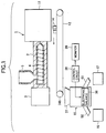
- an injection molding machine 1 has a heating cylinder 2, and a screw 4 which is rotated by an oil motor 3 is provided in the heating cylinder 2.
- a resin material which is supplied to a hopper 5 provided on an upper portion of a proximal end of the heating cylinder 2 is fed into a mold 11 while being melted by the screw 4.
- Abelt conveyor 12 serving as a conveying means is provided below the mold 11, and connector housings 14 serving as synthetic resin products which are ejected from the mold 11 are conveyed to a weight inspecting apparatus by this belt conveyor 12.
- the weight of the connector housing 14 is then measured by the weight inspecting apparatus 15, and a determination is made as to whether the connector housing 14 is nondefective or there is a possibility of the connector housing 14 being defective. Subsequently, the nondefective product is sent to a nondefective-product collecting box 16, while the connector housing 14 having the possibility of being defective is sent to a defective-product collecting box 17.
- the belt conveyor 12 has a pair of supporting frames 18 and 19 which are disposed on both sides of the belt conveyor 12 and are disposed in parallel to each other at an interval therebetween.
- a conveyor belt 20 which circulatingly moves in a fixed direction is trained between unillustrated two rotating rollers mounted at upstream end portions and downstream end portions of the supporting frames 18 and 19.
- Restricting plates 21 and 22 are respectively fixed to downstream end portions of the supporting frames 18 and 19. Downstream end portions of the restricting plates 21 and 22 are formed by being bent toward the inner side of the conveyor belt 20.
- the connector housings 14 which have been conveyed from the upstream end portion of the conveyor belt 20 are gathered together to a central portion or its vicinity of the conveyor belt 20 by the restricting plates 21 and 22.
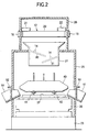
- a windproof cover 25 made of a transparent or semitransparent resin is provided on an upper surface of a base 23 of the weight inspecting apparatus 15 to allow the inside to be confirmed.
- the windproof cover 25 may be formed of an opaque member.
- a hood 26 made of a transparent synthetic resin is provided on top of the windproof cover 25. A downstream end portion of the belt conveyor 12 is covered by this hood 26.
- a square charging barrel 27 is penetrating provided in an upper portion of the windproof cover 25 at a position located inside the hood 26. This charging barrel 27 is located immediately below the downstream end portion of the belt conveyor 12.
- the connector housings 14 which have been conveyed by the belt conveyor 12 are charged through a supply port 27a which is formed at an upper portion of the charging barrel 27 in such a manner as to flare toward the outside. The reason the supply port 27a is flared is to prevent the connector housings 14 from falling off the charging barrel 27.
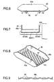
- a plurality of inclined plates 30 and 31 (two in this embodiment) serving as inclined members are provided in a portion excluding the supply port 27a.
- the respective inclined plates 30 and 31 are provided in such a manner as to be vertically offset and to be staggered on the left- and right-hand sides, and are respectively inclined downward.
- distal end portions of the inclined plates 30 and 31 are located on the lower side than proximal portions thereof.
- the distal end portions of the inclined plates 30 and 31, when seenprojected from the vertical direction, overlapping portions are present. For this reason, the connector housings 14 supplied to the charging barrel 27 are unfailingly brought into contact with either one of the inclined plates 30 and 31.
- a gap S is formed between the upper inclined plate 30 and the lower inclined plate 31. Through this gap S, the connector housings 14 are discharged from a discharge port 27b formed in a lower portion of the charging barrel 27.
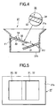
- the angles of inclination, ⁇ 1 and ⁇ 2, of the inclined plates 30 and 31 are set in the range of 30° - 45° with respect to a side surface (vertical direction) of the windproof cover 25. Apart from this numerical range, the angles of inclination, ⁇ 1 and ⁇ 2, may be set to arbitrary values within the range of 25° - 60°.
- Elastic mats 32 are respectively disposed on the upper surfaces of the inclined plates 30 and 31.
- Each elastic mat 32 is formed by bonding together a surface cloth 34 and an expanded base material 33 serving as a foam member formed of rubber or a synthetic resin by an adhesive agent.
- This expanded base material 33 excels in stretchability and is lightweight.
- the surface cloth 34 is made from synthetic fibers having an extremely low coefficient of friction. For this reason, even if the connector housing 14 which is small-sized and has a complex shape, the connector housing 14 is not caught by the surface cloth 34.
- a wet suit cloth is for the elastic mat 32.
- the thickness of the expanded base material 33 is set to 4 to 7 mm. Apart from this numerical range, the thickness of the expanded base material 33 may be changed to an arbitrary value within the range of 2 to 10 mm. Meanwhile, the thickness of the surface cloth 34 is set to 1 to 2 mm. Apart from this numerical range, the thickness of the surface cloth 34 may be changed to an arbitrary value within the range of 1 to 3 mm
- an electronic balance 36 serving as a weight measuring device is provided inside the windproof cover 25 at a position located above the base 23. In other words, the entire surroundings of the electronic balance are covered by the windproof cover 25. Thanks to the presence of the windproof cover 25, the electronic balance is prevented from being subjected to a side wind.
- the electronic balance 36 is a so-called electromagnetic balance provided with a measurement table 37 on which objects to be measured (connector housings 14) are placed.
- the electronic balance 36 in accordance with this embodiment one having a weighing capacity of 410 g and a high-accuracy minimum reading of 0.001 g is used.
- a control circuit 38 serving as a control means, a storage means, and a determining means is electrically connected to the electronic balance 36.
- Various programs necessary for the electronic balance 36 are stored in the control circuit 38.
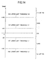
- the total weight of a plurality of connector housings 14 to be subject to weight inspection is set as a reference value, and a first upper-limit threshold H1 which is greater by a predetermined value than that reference value is stored in the memory provided in the control circuit 38.
- the first upper-limit threshold H1 is set to inspect whether the connector housings 14 are nondefective or not.
- the control circuit 38 determines whether or not the total weight of the connector housings 14 is greater than the first upper-limit threshold H1. On the basis of the result of the determination that the total weight is greater than the first upper-limit threshold H1, the control circuit 38 determines that at least one of the connector housings 14 is defective.
- the first upper-limit threshold H1 is set to +20 mg with respect to that reference value.
- the first upper-limit threshold H1 is +1025-fold the reference value.
- the first upper-limit threshold H1 may be changed to an arbitrary value in the range of +1000- to 1200-fold the reference value apart from the aforementioned value.
- a first lower-limit threshold L1 which is smaller by a predetermined value than that reference value of the total weight of the connector housings 14 subject to weight inspection is stored in the memory provided in the control circuit 38. Namely, the first lower-limit threshold L1 is set to inspect whether the connector housings 14 are nondefective or not.
- the control circuit 38 determines whether or not the total weight of the connector housings 14 is less than the first lower-limit threshold L1. On the basis of the result of the determination that the total weight is less than the first lower-limit threshold L1, the control circuit 38 determines that at least one of the connector housings 14 is defective.
- a second lower-limit threshold L2 which is yet smaller than the first lower-limit threshold L1 is stored in the memory provided in the control circuit 38.
- This second lower-limit threshold L2 is set to inspect whether or not the total number of the connector housings 14 placed on a receiving tray 40 is smaller than a predetermined number.
- the control circuit 38 determines whether or not the total weight of the connector housings 14 is less than the second lower-limit threshold L2. On the basis of the result of the determination that the total weight is less than the second lower-limit threshold L2, the control circuit 38 determines that the number of the connector housings 14 whose weight has been measured is less than the predetermined number.
- the first lower-limit threshold L1 is set to -20 mg with respect to that reference value.
- the first lower-limit threshold L1 is -1025-fold the reference value.
- the first lower-limit threshold L1 may be changed to an arbitrary value in the range of -1000- to -1200-fold the reference value apart from the aforementioned value.
- the second lower-limit threshold L2 is set to -150 mg with respect to the reference value.
- the second lower-limit threshold L2 is about -137-fold the reference value, i.e., 7.5-fold the first lower-limit threshold L1.
- the second lower-limit threshold L2 may be changed to an arbitrary value in the range of -1000 to 120- to 500-fold the reference value apart from the aforementioned value. Further, the second lower-limit threshold L2 may be changed to an arbitrary value in the range of 6- to 10-fold the first lower-limit threshold L1.
- a monitor 39 serving as a display means constituted by an LCD, a CRT, or the like is electrically connected to the control circuit 38.
- the monitor 39 is adapted to display the cause of the connector housing 14 becoming defective.
- the two lifting/lowering arms 41 and 42 are raised to allow the receiving tray 40 to be disposed at a receiving position P1 spaced apart from the electronic balance 36.
- the two lifting/lowering arms 41 and 42 are lowered slowly, allowing the receiving tray 40 to be disposed at a measuring position P2 in contact with the measurement table 37.
- the reason for separately providing the receiving position P1 and the measuring position P2 for the receiving tray 40 is that if the connector housings 14 subject to weight inspection are directly dropped onto the measurement table 37, a shock occurs and can be a cause of failure.
- one of the lifting/lowering arms 41 and 42 is raised, and the other one is lowered, allowing the receiving tray 40 to be tilted in either leftward or rightward direction.
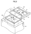
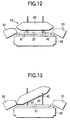
- front and rear side walls 40a and 40b of the receiving tray 40 are formed by being bent upward so as to reliably receive the connector housings 14 which are dropped from the belt conveyor 12. Specifically, the front and rear side walls 40a and 40b of the receiving tray 40 are bent orthogonally to the bottom surface.
- left and right end portions of a bottom portion 40c of the receiving tray 40 are formed by being bent diagonally upward.
- a multiplicity of projections 44 which are elevated toward the inner side of the receiving tray 40 are formed on the entire bottom portion 40c of the receiving tray 40. Due to the presence of the projections 44, the overall upper surface of the bottom portion 40c of the receiving tray 40 is formed as an irregular surface. For this reason, when the connector housing 14 has entered the receiving tray 40, the area of contact between the connector housing 14 and the bottom portion 40c becomes small.
- the projections 44 are all of the same size, are formed in a semi-elliptical cross-sectional shape (elongated dome shape), and are elongated along the direction in which the connector housing 14 is discharged from the receiving tray 40 (in the left-and-right direction in Fig. 2). The reason for this is to allow the connector housings 14 to be discharged smoothly from the receiving tray 40. As viewed from the back-and-forth direction (the direction of A in Fig. 10), the left-and-right direction (the direction of B in Fig. 10), and the diagonal direction (the direction of C in Fig. 10), the projections 44 are regularly arranged at fixed intervals in all of these directions.
- the projections 44 arranged in the back-and-forth direction A or the left-and-right direction B are viewed, the projections 44 are arranged in a relationship of being positionally offset alternately. Namely, the projections 44 are respectively arranged in a staggered manner in the back-and-forth and left-and-right directions A and B.
- trough-shaped discharge passages 50 and 51 extending diagonally downward are respectively provided in the vicinities of the left and right sides of the receiving tray 40 at positions located at left and right side walls of the windproof cover 25.
- Each of the discharge passages 50 and 51 projects from the interior of the windproof cover 25 to the outside.
- the connector housings 14 which slip down from the receiving tray 40 are adapted to be guided to the nondefective-product collecting box 16 or the defective-product collecting box 17 through the discharge passage 50 or 51.
- Vertically movable shutters 52 and 53 are respectively provided midway in the discharge passages 50 and 51 along the left and right side walls of the windproof cover 25.
- Thee shutters 52 and 53 have unillustrated air cylinders as their driving sources. As the shutters 52 and 53 are lowered, the discharge passages 50 and 51 are closed, whereas as the shutters 52 and 53 are raised, the discharge passages 50 and 51 are opened. Accordingly, since the discharge passages 50 and 51 can be opened only when necessary, a side wind is prevented from entering the windproof cover 25 as practically as possible.
- a plurality of connector housings 14 drop onto an upstream end of the belt conveyor 12 at a time . Further, at the downstream end of the belt conveyor 12, the plurality of connector housings 14 are gathered together to the central portion or its vicinity by the restricting plates 21 and 22, and are conveyed to the weight inspecting apparatus 15. Namely, the plurality of connector housings 14 dropped from the belt conveyor 12 are charged into the charging barrel 27 through the hood 26.
- each connector housing 14 first drops onto the elastic mat 32 provided on the upper inclined plate 30, and slips down to a lower portion of the upper inclined plate 30. Subsequently, the connector housing 14, while being brought into contact with the elastic mat 32 provided on the lower inclined plate 31, slips down on the lower inclined plate 31, passes through the gap S, and is discharged from the discharge port 27b of the charging barrel 27.
- the connector housing 14 which first dropped onto the lower inclined plate 31 without dropping onto the upper inclined plate 30, passes through the gap S, and is discharged from the discharge port 27b of the charging barrel 27.
- the connector housings 14 are unfailingly brought into contact with either one or both of the elastic mats 32 of the two inclined plates 30 and 31 before being discharged from the discharge port 27b of the charging barrel 27.
- the connector housings 14 discharged from the discharge port 27b of the charging barrel 27 drop onto the receiving tray 40 which has already been on standby at the receiving position P1. Then, the lifting/lowering arms 41 and 42 are lowered simultaneously, and the receiving tray 40 moves slowly to the measuring position P2. At this measuring position P2, the receiving plate 40 with the connector housings 14 placed thereon is placed on the measurement table 37 of the electronic balance 36. It should be noted that unillustrated legs are respectively provided projectingly at four corners of the outer surface of the bottom portion 40c of the receiving tray 40, and these four legs are brought into contact with the measurement table 37. At this time, a gap is produced between the lower surface of the receiving tray 40 and the obverse surface of the measurement table 37, and the lifting/lowering arms 41 and 42 are located in this gap and are positioned so as to be spaced apart from the receiving tray 40.
- the weight of the receiving tray 40 including the connector housings 14 is measured. Then, the total weight of only the connector housings 14 obtained by subtracting the weight of the receiving tray 40 from that measured value is displayed on the monitor 39 as the result of measurement.
- the control circuit 38 provided in the weight inspecting apparatus 15 calculates the weight of the connector housings 14 on the basis of a measurement signal outputted from the measurement table 37, and determines whether that calculated weight is greater than the first upper-limit threshold H1 stored in advance in the memory or is less than the first lower-limit threshold L1 similarly stored therein.
- the control circuit 38 determines that all the connector housings 14 are nondefective. On the other hand, if the the measured value of the connector housings 14 has not fallen within the allowance, i.e., if the measured value is either greater than the first upper-limit threshold H1 or less than the first lower-limit threshold L1, the control circuit 38 determines that at least one of the connector housings 14 is defective.
- the receiving tray 40 is tilted diagonally. Therefore, the plurality of connector housings 14 slip to the left-hand side on the bottom portion 40c of the receiving tray 40, and are allowed to drop to the nondefective-product collecting box 16 through the left-hand discharge passage 50. Subsequently, after the lapse of a fixed time, the left-hand lifting/lowering arm 41 is raised, so that the receiving tray 40 returns to the receiving position P1.
- the plurality of connector housings 14 slip to the right-hand side on the bottom portion 40c of the receiving tray 40, and are allowed to drop to the defective-product collecting box 17 through the right-handdischarge passage 51. Subsequently, after the lapse of a fixed time, the right-hand lifting/lowering arm 42 is raised, so that the receiving tray 40 returns to the receiving position P1.
- the control circuit 38 determines whether or not the measured value is greater than the second upper-limit threshold H2. If it is determined that the measured value is not greater than the second upper-limit threshold H2, i.e., if the measured value is located between the first and second upper-limit thresholds H1 and H2, the control circuit 38 causes the monitor 39 to display that burrs have occurred on the connector housing 14 or a foreign object has been attached thereto.
- the control circuit 38 causes the monitor 39 to display that the total weight of the connector housings 14 more numerous than the number appropriate for inspection has been measured. Then, through the judgment of the operator who viewed this monitor 39, these connector housings 14 are removed from the receiving tray 40.
- the case in which the connector housings 14 more numerous than the number appropriate for inspection are placed on the receiving tray 40 is the case in which one or more connector housings 14 molded still remain on the receiving tray 40. Then, since the subsequently molded connector housings 14 are placed on the receiving tray 40, the total number of the connector housings 14 increases . As a major cause for this trouble, it is possible to cite the case in which when the connector housings 14 slip down on the receiving tray 40, the connector housings 14 are electrically attracted to each other by static electricity with which they are charged.
- the control circuit 38 determines whether or not the measured value is less than the second lower-limit threshold L2. If it is determined that the measured value is not less than the second lower-limit threshold L2, i.e., if the measured value is located between the first and second lower-limit thresholds L1 and L2, the control circuit 38 causes the monitor 39 to display that at least one of the connector housings 14 is nondefective due to a short shot or the like.
- the control circuit 38 causes the monitor 39 to display that the total weight of the connector housings 14 less than the number appropriate for inspection has been measured. Then, through the judgment of the operator who viewed this monitor 39, these connector housings 14 are removed from the receiving tray 40.
- the second upper-limit threshold H2 which is yet greater than the first upper-limit threshold H1 is stored in the control circuit. 38.
- a determination is made by the control circuit 38 as to whether or not the second upper-limit threshold H2 has also been exceeded. For this reason, it canbe understood that if the second upper-limit threshold H2 has not been exceeded, burrs or the like have occurred on at least one of the connector housings 14, and if the second upper-limit threshold H2 has been exceeded, connector housings 14 in a number more numerous than the predetermined number have been measured. Accordingly, since it is possible to specify due to what causes the connector housings 14 have become defective, it is possible to improve the inspection accuracy of the connector housings 14.
- the second lower-limit threshold L2 which is yet smaller than the first lower-limit threshold L1 is stored in the control circuit 38.
- a determination is made by the control circuit 38 as to whether or not the measured weight is less than the second lower-limit threshold L2. For this reason, it can be understood that if the measured weight is not less than the second lower-limit threshold L2, a short shot or the like has occurred in the connector housing 14, and if the measured weight is less than the second lower-limit threshold L2, connector housings 14 in a number less than the predetermined number have been measured. In this case as well, since it is possible to specify due to what causes the connector housings 14 have become defective, it is possible to improve the inspection accuracy of the connector housings 14.
- the respective thresholds L1, L2, H1, and H2 are stored in the memory of the control circuit 38, only one of the groups of the first and second upper-limit thresholds H1 and H2 and the first and second lower-limit thresholds L1 and L2 may be stored.
- the control circuit 38 when the total weight of the connector housings 14 is greater than the first upper-limit threshold H1, the control circuit 38 is made to determnine whether or not the total weight of the connector housings 14 is yet greater than the second upper-limit threshold H2.
- the control circuit 38 when the total weight of the connector housings 14 is less than the first lower-limit threshold L1, the control circuit 38 is made to determnine whether or not the total weight of the connector housings 14 is yet less than the second lower-limit threshold L2.
- the connector housings 14 are defective, their causes are displayed on the monitor 39 such as the LCD or the CRT.
- the monitor 39 such as the LCD or the CRT.
- an indicating lamp constituted by, for instance, an LED or a lamp, and effect printing on paper by using a printer.
- a weight inspecting apparatus in which a receiving member for placing thereon a plurality of resin products molded by in jectionmolding is provided, the receiving member is movable between a receiving position for receiving the resin products at a position spaced apart from a weight measuring instrument and a measuring position for measuring the weight of the resin products on the weight measuring instrument, and inspection is performed as to whether or not the resin products are nondefective on the basis of whether or not the total weight of the plurality of resin products placed on the receiving member at the measuring position is greater than a first upper-limit threshold
- the weight inspecting apparatus comprising: storage means for storing a second upper-limit threshold which is yet greater than the first upper-limit threshold; and determining means for determining whether or not the total weight of the resin products is greater than the second upper-limit threshold.
- a weight inspecting apparatus in which a receiving member for placing thereon a plurality of resin products molded by injection molding is provided, the receiving member is movable between a receiving position for receiving the resin products at a position spaced apart from a weight measuring instrument and a measuring position for measuring the weight of the resin products on the weight measuring instrument, and inspection is performed as to whether or not the resin products are nondefective on the basis of whether or not the total weight of the plurality of resin products placed on the receiving member at the measuring position is less than a first lower-limit threshold
- the weight inspecting apparatus comprising: storage means for storing a second lower-limit threshold which is yet smaller than the first lower-limit threshold; and determining means for determining whether or not the total weight of the resin products is less than the second lower-limit threshold.
- An injection molding system comprising: an injection molding machine including a mold for molding resin products; conveying means for receiving and conveying the resin products which are dropped from the injection molding machine; and a weight inspecting apparatus for inspecting the weight of the resin products which have been conveyed by the conveying means, wherein the weight inspecting apparatus is constructed in accordance with any one of aspects 1 to 3.
- a weight inspection method in which a receiving member for placing thereon a plurality of resin products molded by injection molding is provided, the receiving member is movable between a receiving position for receiving the resin products at a position spaced apart from a weight measuring instrument and a measuring position for measuring the weight of the resin products on the weight measuring instrument, and inspection is performed as to whether or not the resin products are nondefective on the basis of whether or not the total weight of the plurality of resin products placed on the receiving member at the measuring position is greater than a first upper-limit threshold, the weight inspection method comprising the steps of: setting a second upper-limit threshold which is yet greater than the first upper-limit threshold; and determining whether or not the total weight of the resin products is greater than the second upper-limit threshold after a determination is made that the total weight of the resin products is greater than the first upper-limit threshold.
- a weight inspection method in which a receiving member for placing thereon a plurality of resin products molded by injection molding is provided, the receiving member is movable between a receiving position for receiving the resin products at a position spaced apart from a weight measuring instrument and a measuring position for measuring the weight of the resin products on the weight measuring instrument, and inspection is performed as to whether or not the resin products are nondefective on the basis of whether or not the total weight of the plurality of resin products placed on the receiving member at the measuring position is less than a first lower-limit threshold, the weight inspection method comprising the steps of:
- a weight inspection method in which there are provided an injection molding machine including a mold for molding resin products, conveying means for receiving and conveying the resin products which are dropped from the injection molding machine, and a weight inspecting apparatus for inspecting the weight of the resin products which have been conveyed by the conveying means, and inspection is performed as to whether or not the resin products are nondefective on the basis of whether or not the total weight of the plurality of resin products placed on the receiving member at a measuring position is between a first upper-limit threshold and a first lower-limit threshold, the weight inspection method comprising the steps of: setting a second upper-limit threshold which is yet greater than the first upper-limit threshold and a second lower-limit threshold which is yet less thanthe first lower-limit threshold; and determining whether or not the total weight of the resin products is greater than the second upper-limit threshold after a determination is made that the total weight of the resin products is greater than the first upper-limit threshold, and determining whether or not the total weight of the resin products is less than the second lower-limit threshold after a determination
- a weight inspecting apparatus in which a receiving member for placing thereon a plurality of resin products molded by in jectionmolding is provided, the receiving member is movable between a receiving position for receiving the resin products at a position spaced apart from a weight measuring instrument and a measuring position for measuring the weight of the resin products on the weight measuring instrument, and inspection is performed as to whether or not the plurality of resin products placed on the receiving member at the measuring position are nondefective, the weight inspecting apparatus comprising:
Landscapes
- Physics & Mathematics (AREA)
- General Physics & Mathematics (AREA)
- Engineering & Computer Science (AREA)
- Manufacturing & Machinery (AREA)
- Mechanical Engineering (AREA)
- Injection Moulding Of Plastics Or The Like (AREA)
- Investigating Materials By The Use Of Optical Means Adapted For Particular Applications (AREA)
Applications Claiming Priority (2)
| Application Number | Priority Date | Filing Date | Title |
|---|---|---|---|
| JP2000234479 | 2000-08-02 | ||
| JP2000234479A JP3615997B2 (ja) | 2000-08-02 | 2000-08-02 | 重量検査装置 |
Publications (3)
| Publication Number | Publication Date |
|---|---|
| EP1178291A2 true EP1178291A2 (de) | 2002-02-06 |
| EP1178291A3 EP1178291A3 (de) | 2002-06-05 |
| EP1178291B1 EP1178291B1 (de) | 2004-04-07 |
Family
ID=18726841
Family Applications (1)
| Application Number | Title | Priority Date | Filing Date |
|---|---|---|---|
| EP01118386A Expired - Lifetime EP1178291B1 (de) | 2000-08-02 | 2001-07-27 | Gewichtsinspektionsvorrichtung |
Country Status (4)
| Country | Link |
|---|---|
| US (1) | US6696649B2 (de) |
| EP (1) | EP1178291B1 (de) |
| JP (1) | JP3615997B2 (de) |
| DE (1) | DE60102633T2 (de) |
Cited By (3)
| Publication number | Priority date | Publication date | Assignee | Title |
|---|---|---|---|---|
| US7880900B2 (en) | 2008-08-19 | 2011-02-01 | Silverbrook Research Pty Ltd | Measuring apparatus for performing positional analysis on an integrated circuit carrier |
| US7924440B2 (en) | 2008-08-19 | 2011-04-12 | Silverbrook Research Pty Ltd | Imaging apparatus for imaging integrated circuits on an integrated circuit carrier |
| CN106338326A (zh) * | 2016-08-29 | 2017-01-18 | 芜湖凯尔电气科技有限公司 | 绿色电池称重装置 |
Families Citing this family (4)
| Publication number | Priority date | Publication date | Assignee | Title |
|---|---|---|---|---|
| US6651821B2 (en) * | 2000-04-17 | 2003-11-25 | Mettler-Toledo, Inc. | Tilting platform checkweighing device |
| JP4167282B2 (ja) * | 2006-10-27 | 2008-10-15 | 日精樹脂工業株式会社 | 射出成形機の支援装置 |
| JP5128409B2 (ja) * | 2008-08-04 | 2013-01-23 | 古河電気工業株式会社 | 電子部品内蔵コネクタ及びその製造方法、並びに電子部品内蔵コネクタの製造装置 |
| CN114308714A (zh) * | 2020-09-30 | 2022-04-12 | 日本三阳莫大小株式会社 | 编织物品质管理装置 |
Family Cites Families (7)
| Publication number | Priority date | Publication date | Assignee | Title |
|---|---|---|---|---|
| DE3538516A1 (de) | 1985-10-30 | 1987-05-07 | Philips Patentverwaltung | Gewichtsregler fuer eine regelbare spritzgiessmaschine |
| JP2586954B2 (ja) | 1989-11-24 | 1997-03-05 | ファナック株式会社 | 射出成形機における成形不良対策方法 |
| JPH06194415A (ja) | 1992-09-30 | 1994-07-15 | American Teleph & Telegr Co <Att> | 論理回路の試験方法とその装置 |
| JP3181736B2 (ja) | 1992-12-25 | 2001-07-03 | 三菱電機株式会社 | Ic機能試験装置及び試験方法 |
| US5817988A (en) | 1994-08-18 | 1998-10-06 | Sumitomo Wiring Systems, Ltd. | Weight checker for moldings |
| JP3327691B2 (ja) | 1994-08-18 | 2002-09-24 | 住友電装株式会社 | 重量検査装置 |
| JP3327690B2 (ja) | 1994-08-18 | 2002-09-24 | 住友電装株式会社 | 重量検査装置 |
-
2000
- 2000-08-02 JP JP2000234479A patent/JP3615997B2/ja not_active Expired - Fee Related
-
2001
- 2001-07-25 US US09/911,410 patent/US6696649B2/en not_active Expired - Fee Related
- 2001-07-27 EP EP01118386A patent/EP1178291B1/de not_active Expired - Lifetime
- 2001-07-27 DE DE60102633T patent/DE60102633T2/de not_active Expired - Fee Related
Cited By (3)
| Publication number | Priority date | Publication date | Assignee | Title |
|---|---|---|---|---|
| US7880900B2 (en) | 2008-08-19 | 2011-02-01 | Silverbrook Research Pty Ltd | Measuring apparatus for performing positional analysis on an integrated circuit carrier |
| US7924440B2 (en) | 2008-08-19 | 2011-04-12 | Silverbrook Research Pty Ltd | Imaging apparatus for imaging integrated circuits on an integrated circuit carrier |
| CN106338326A (zh) * | 2016-08-29 | 2017-01-18 | 芜湖凯尔电气科技有限公司 | 绿色电池称重装置 |
Also Published As
| Publication number | Publication date |
|---|---|
| JP2002046163A (ja) | 2002-02-12 |
| US6696649B2 (en) | 2004-02-24 |
| JP3615997B2 (ja) | 2005-02-02 |
| EP1178291B1 (de) | 2004-04-07 |
| US20020023784A1 (en) | 2002-02-28 |
| EP1178291A3 (de) | 2002-06-05 |
| DE60102633T2 (de) | 2005-05-19 |
| DE60102633D1 (de) | 2004-05-13 |
Similar Documents
| Publication | Publication Date | Title |
|---|---|---|
| EP1178291B1 (de) | Gewichtsinspektionsvorrichtung | |
| KR101096789B1 (ko) | 벨트식 중량 측정기를 이용한 농산물 선별 장치 | |
| KR102225450B1 (ko) | 콤비형 중량 선별 장치 | |
| EP2002770B1 (de) | Verfahren zur Überwachung des Aufschlagens von Eiern, Eiaufnahmevorrichtung zur Aufnahme des Inhalts eines Eies und Eiaufschlagvorrichtung mit einer solchen Eiaufnahmevorrichtung | |
| EP1411347B1 (de) | Vorrichtung zur Inspektion flacher Tabletten | |
| JP3327691B2 (ja) | 重量検査装置 | |
| KR101844505B1 (ko) | 소프트렌즈 품질 검사장치 | |
| KR20110123707A (ko) | 벨트식 중량 측정기를 이용한 농산물 선별 장치 | |
| CN218517234U (zh) | 一种包装盒质量检测机 | |
| CN111504431A (zh) | 一种扫码称重测体积一体机及其分拣方法 | |
| CA1049448A (en) | Method and apparatus for detecting flaws in circular tablet | |
| JP3677438B2 (ja) | 射出成形システム | |
| JP3327690B2 (ja) | 重量検査装置 | |
| CN207060566U (zh) | 炸药包装件自动计量及甄别装置 | |
| JP3677437B2 (ja) | 射出成形システム | |
| JP2002048625A (ja) | 重量検査装置 | |
| JP2002054985A (ja) | 重量検査装置 | |
| JP2002048632A (ja) | 重量検査装置 | |
| JP2003094485A (ja) | 重量検査装置 | |
| JP2002048626A (ja) | 重量検査装置 | |
| JP2003121248A (ja) | 組合せ計量装置 | |
| CN217980500U (zh) | 一种粉末冶金双通道自动检验线设备 | |
| JP7278583B2 (ja) | 編織物品質管理装置 | |
| JP3816172B2 (ja) | 仕分け監視装置 | |
| KR200177308Y1 (ko) | 반도체의 타블렛 공급장치 |
Legal Events
| Date | Code | Title | Description |
|---|---|---|---|
| PUAI | Public reference made under article 153(3) epc to a published international application that has entered the european phase |
Free format text: ORIGINAL CODE: 0009012 |
|
| AK | Designated contracting states |
Kind code of ref document: A2 Designated state(s): AT BE CH CY DE DK ES FI FR GB GR IE IT LI LU MC NL PT SE TR |
|
| AX | Request for extension of the european patent |
Free format text: AL;LT;LV;MK;RO;SI |
|
| PUAL | Search report despatched |
Free format text: ORIGINAL CODE: 0009013 |
|
| AK | Designated contracting states |
Kind code of ref document: A3 Designated state(s): AT BE CH CY DE DK ES FI FR GB GR IE IT LI LU MC NL PT SE TR |
|
| AX | Request for extension of the european patent |
Free format text: AL;LT;LV;MK;RO;SI |
|
| RIC1 | Information provided on ipc code assigned before grant |
Free format text: 7G 01G 13/02 A, 7G 01G 15/00 B, 7B 29C 45/76 B |
|
| 17P | Request for examination filed |
Effective date: 20020722 |
|
| AKX | Designation fees paid |
Designated state(s): DE GB |
|
| GRAP | Despatch of communication of intention to grant a patent |
Free format text: ORIGINAL CODE: EPIDOSNIGR1 |
|
| GRAS | Grant fee paid |
Free format text: ORIGINAL CODE: EPIDOSNIGR3 |
|
| GRAA | (expected) grant |
Free format text: ORIGINAL CODE: 0009210 |
|
| AK | Designated contracting states |
Kind code of ref document: B1 Designated state(s): DE GB |
|
| REG | Reference to a national code |
Ref country code: GB Ref legal event code: FG4D |
|
| REF | Corresponds to: |
Ref document number: 60102633 Country of ref document: DE Date of ref document: 20040513 Kind code of ref document: P |
|
| REG | Reference to a national code |
Ref country code: IE Ref legal event code: FG4D |
|
| RAP2 | Party data changed (patent owner data changed or rights of a patent transferred) |
Owner name: SUMIDENSO PLATECH, LTD Owner name: SUMITOMO WIRING SYSTEMS, LTD. |
|
| PLBE | No opposition filed within time limit |
Free format text: ORIGINAL CODE: 0009261 |
|
| STAA | Information on the status of an ep patent application or granted ep patent |
Free format text: STATUS: NO OPPOSITION FILED WITHIN TIME LIMIT |
|
| 26N | No opposition filed |
Effective date: 20050110 |
|
| REG | Reference to a national code |
Ref country code: IE Ref legal event code: MM4A |
|
| PGFP | Annual fee paid to national office [announced via postgrant information from national office to epo] |
Ref country code: GB Payment date: 20080806 Year of fee payment: 8 |
|
| PGFP | Annual fee paid to national office [announced via postgrant information from national office to epo] |
Ref country code: DE Payment date: 20090723 Year of fee payment: 9 |
|
| GBPC | Gb: european patent ceased through non-payment of renewal fee |
Effective date: 20090727 |
|
| PG25 | Lapsed in a contracting state [announced via postgrant information from national office to epo] |
Ref country code: GB Free format text: LAPSE BECAUSE OF NON-PAYMENT OF DUE FEES Effective date: 20090727 |
|
| PG25 | Lapsed in a contracting state [announced via postgrant information from national office to epo] |
Ref country code: DE Free format text: LAPSE BECAUSE OF NON-PAYMENT OF DUE FEES Effective date: 20110201 |
|
| REG | Reference to a national code |
Ref country code: DE Ref legal event code: R119 Ref document number: 60102633 Country of ref document: DE Effective date: 20110201 |