EP1174554A1 - Aufsatzdichtung für eine Pfosten-/Riegel-Konstruktion - Google Patents
Aufsatzdichtung für eine Pfosten-/Riegel-Konstruktion Download PDFInfo
- Publication number
- EP1174554A1 EP1174554A1 EP01117236A EP01117236A EP1174554A1 EP 1174554 A1 EP1174554 A1 EP 1174554A1 EP 01117236 A EP01117236 A EP 01117236A EP 01117236 A EP01117236 A EP 01117236A EP 1174554 A1 EP1174554 A1 EP 1174554A1
- Authority
- EP
- European Patent Office
- Prior art keywords
- top seal
- seal according
- base web
- web
- groove
- Prior art date
- Legal status (The legal status is an assumption and is not a legal conclusion. Google has not performed a legal analysis and makes no representation as to the accuracy of the status listed.)
- Granted
Links
- 238000010276 construction Methods 0.000 title claims description 13
- 238000007789 sealing Methods 0.000 claims abstract description 29
- 238000009413 insulation Methods 0.000 claims abstract description 9
- 239000011521 glass Substances 0.000 claims description 30
- 230000003068 static effect Effects 0.000 claims description 6
- 229910000831 Steel Inorganic materials 0.000 description 4
- 239000010959 steel Substances 0.000 description 4
- 238000004804 winding Methods 0.000 description 3
- XAGFODPZIPBFFR-UHFFFAOYSA-N aluminium Chemical compound [Al] XAGFODPZIPBFFR-UHFFFAOYSA-N 0.000 description 2
- 229910052782 aluminium Inorganic materials 0.000 description 2
- 239000000463 material Substances 0.000 description 2
- 230000007704 transition Effects 0.000 description 2
- XLYOFNOQVPJJNP-UHFFFAOYSA-N water Substances O XLYOFNOQVPJJNP-UHFFFAOYSA-N 0.000 description 2
- 229920002943 EPDM rubber Polymers 0.000 description 1
- 230000009286 beneficial effect Effects 0.000 description 1
- 230000000295 complement effect Effects 0.000 description 1
- 238000011161 development Methods 0.000 description 1
- 230000018109 developmental process Effects 0.000 description 1
- 238000001125 extrusion Methods 0.000 description 1
- 210000003746 feather Anatomy 0.000 description 1
- 238000003780 insertion Methods 0.000 description 1
- 230000037431 insertion Effects 0.000 description 1
- 238000009434 installation Methods 0.000 description 1
- 238000004519 manufacturing process Methods 0.000 description 1
- 230000003287 optical effect Effects 0.000 description 1
- 230000006641 stabilisation Effects 0.000 description 1
- 238000011105 stabilization Methods 0.000 description 1
- 239000002023 wood Substances 0.000 description 1
Images




Classifications
-
- E—FIXED CONSTRUCTIONS
- E04—BUILDING
- E04B—GENERAL BUILDING CONSTRUCTIONS; WALLS, e.g. PARTITIONS; ROOFS; FLOORS; CEILINGS; INSULATION OR OTHER PROTECTION OF BUILDINGS
- E04B2/00—Walls, e.g. partitions, for buildings; Wall construction with regard to insulation; Connections specially adapted to walls
- E04B2/88—Curtain walls
- E04B2/96—Curtain walls comprising panels attached to the structure through mullions or transoms
- E04B2/967—Details of the cross-section of the mullions or transoms
-
- E—FIXED CONSTRUCTIONS
- E04—BUILDING
- E04D—ROOF COVERINGS; SKY-LIGHTS; GUTTERS; ROOF-WORKING TOOLS
- E04D3/00—Roof covering by making use of flat or curved slabs or stiff sheets
- E04D3/02—Roof covering by making use of flat or curved slabs or stiff sheets of plane slabs, slates, or sheets, or in which the cross-section is unimportant
- E04D3/06—Roof covering by making use of flat or curved slabs or stiff sheets of plane slabs, slates, or sheets, or in which the cross-section is unimportant of glass or other translucent material; Fixing means therefor
- E04D3/08—Roof covering by making use of flat or curved slabs or stiff sheets of plane slabs, slates, or sheets, or in which the cross-section is unimportant of glass or other translucent material; Fixing means therefor with metal glazing bars
- E04D2003/0818—Roof covering by making use of flat or curved slabs or stiff sheets of plane slabs, slates, or sheets, or in which the cross-section is unimportant of glass or other translucent material; Fixing means therefor with metal glazing bars the supporting section of the glazing bar consisting of several parts, e.g. compound sections
- E04D2003/0825—Roof covering by making use of flat or curved slabs or stiff sheets of plane slabs, slates, or sheets, or in which the cross-section is unimportant of glass or other translucent material; Fixing means therefor with metal glazing bars the supporting section of the glazing bar consisting of several parts, e.g. compound sections the metal section covered by parts of other material
- E04D2003/0831—Glazing gaskets of particular shape
Definitions
- the invention relates to an attachment seal for a mullion / transom construction, especially for a mullion / transom construction with a static profile on which an attachment or adapter profile can be attached, the attachment seal essentially in cross-section a T-shape with a base bar and two on both sides of the base web, transverse webs extending essentially perpendicular to the base web having.
- Top seals of the generic type are used in the rebate area of a facade or a light roof on a so-called connected to the substructure Attachment profile attached. Such an attachment seal is described in DE 199 01 418 described.
- Top seals of the generic type have the same type as the top seal Invention based on which is essentially formed from the two crosspieces is and has locking elements for locking on the substructure. You point also the middle base, which is connected to the substructure by a screw channel is put up. Drainage and drainage grooves are used for drainage of leachate. They also have a double glass plant level, to compensate for a height difference at the crossing point of the transom and the mullion.
- Top seals are usually made in one piece from EPDM. you will be relatively large-volume or included in the large-volume seals, which are also available in long lengths, e.g. over several facade floors, can be carried out in one piece have to be.
- the object of the invention is to at least partially solve these problems.
- an attachment seal is to be created that is easy to assemble is and improves the thermal insulation in the rebate area.
- the invention first creates an attachment seal for a mullion / transom construction, in which the base bridge has at least one hinge the crossbars is connected.
- the hinges are preferably structurally special simply designed as film hinges.
- the hinges increase the flexibility of the top seal in a structurally simple manner and thus facilitate both their storage on sealing drums also their assembly.
- the base web particularly preferably extends into a rebate space between Fillings and is provided on the side with at least one or more sealing lip (s), which divide the rebate area into several chambers to the side of the base web.
- sealing lips protruding into the glass rebate improve on simple constructive Way the thermal insulation in the rebate.
- the base web is preferably with closed or one-sided open hollow chambers Mistake.
- a closed is also in the region of the crossbars Base formed, which sections the lower end of one of the Cavities limited.
- the closed - but preferably removable - base leads in this area to one that is quite desirable here in production Shape stabilization and for exact positioning of the seal on the substructure.
- Predetermined breaking points or lines for example notches, enable easy removal part of the base before assembly.
- the degree in the area between the predetermined breaking points is always extruded, even if it is for the installation function is not required.
- the top seal can thus be safely extruded and also does not experience excessive deformation when winding the seal on transport and storage rolls.
- the crossbars of the top seals preferably have a glass system and Snap-on lower part, which interlock via a tongue and groove system. Because the contact surfaces the overlapping glass system and snap-in lower part a groove and spring system, the two will slip in a simple manner Components prevented relative to each other.
- the tongue and groove system is constructive designed so that in the intersection area, in which transom and post seals overlap, the grooved surfaces come to rest. This is achieved in that the bolt top seal the groove in the top Glass system and the post-top seal the groove in the lower part the glass system, the rest part. As a result, the contact surfaces are more advantageous Be smooth on each other.
- a latching groove is preferably formed in the latching lower part, an outer die Limiting groove limiting leg slightly inclined inwards by a contact angle is.
- the base of the top seal thus has two locking grooves, the two outer ones Have webs that are oriented inwards when not assembled. This results in contact pressure against the substructure when the seals are installed and therefore a particularly good fit and a good seal.
- Attachment gasket can be produced as an unfolded, elongated profile and then be rolled up for transport or storage. The top seal not twisted and can easily be folded into the mounting position become.
- Fig. 1 shows a horizontal section through a post / transom construction.
- the structural design has an example of a static profile made of steel 1 on which an attachment or adapter profile 2 is attached.
- the Attachment profiles 2 can consist of materials such as steel, aluminum or plastic and be welded, screwed or glued to the static profiles.
- the static profiles can also be made of different materials such as steel, aluminum and wood.
- the top seal 3 is put on and clipped onto the attachment profile 2.
- the top seal 3 has in the section of FIG. 1 essentially a kind of T-shape on.
- the base web 3a of the T adjoins the base web 3a on both sides transverse webs 3b, 3c running essentially perpendicular to the base web.
- Of the top seal 3 or its crossbars 3b, 3c and an outer Glass system gasket 4 are fillings 5, such as Insulated glass panes bordered.
- the outer glass contact seals 4 are held in grooves in a clamping profile 6.
- the clamping profile 6 is with a screw 8 with the attachment profile 2, which is fixed is attached to the static profile 1, screwed. For optical reasons can still a cover 7 to be clipped onto the clamping profile 6.
- the base web 3a is via hinges (here film hinges) 19 with the crossbars 3b, 3c connected.
- the base web 3a extends into the rebate space between the fillings 5.
- the base web 3a is laterally with sealing lips 9 provided that the rebate space laterally of the base web 3a in several chambers 10, 11th divide and thus improve the thermal insulation.
- the inner chamber 11 forms at the same time a drainage groove, which is used to drain the penetrated into the fold Water serves.
- the top seal 3 also has in its central part or in the area of Base web 3a further hollow chambers 12, 13 and 14.
- the inner chamber 12 in Edge area to the base of the two crosspieces 3b, 3c is for putting on the Seal designed for the attachment profile, the middle hollow chamber 13 is used Thermal insulation and the hollow chamber 14 open to the outside is used as a guide or locking groove designed for centering or for snapping in other components.
- Fig. 2 shows a vertical transom section through the post / transom construction of Fig. 1.
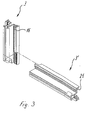
- An essential difference of the top seals 3, 3 'for bolts and Post lies in that the sealing web 15 of the cross webs 3b, 3c of the top seal 3 'for the bolt with the glass system 16, however, the transverse webs 3b, 3c Attachment seal 3 for the post is connected to the locking lower part 21. hereby remains in the intersection area where the seals overlap (see also Fig. 3), the drainage groove 11 obtained.
- the seal for the bolt is in this area of overlap the locking lower part 21 and matching the Gasket for the post removed the glass system 16.
- the bottom of the groove becomes this Groove 18 essentially by a perpendicular to the main direction of extension of the Base web 3a aligned groove web 18a formed while the groove bottom of the groove 14 in FIG. 1 consists of two groove webs 14a, 14b which complement one another to form a type "V".
- the hinge-type according to the invention is common to the attachment seals 3, 3 ' Joint 19 at the end of the sealing webs 15 in the transition to the outward Sealing walls 20 or in the area of the transitions between the base web 3a and the crossbars 3b, 3c. This ensures that it can be easily assembled.
- top seal 3 shows the problem of the division of the glass system 16 and the locking lower part 21 in the cross joint area when the seals overlap brings with it.
- the glass systems of the top seals must be on one level run.
- the top seals are designed to reach the drainage grooves notched that the glass system of the top seal 3 for the post partially is separated out, whereas the locking lower part 21 of the top seal 3 'for the bolt is removed. This ensures that the filling system one level.
- the crossbars 3b, 3c of the top seals 3, 3 'of Figures 1, 4 and 5 have one Glass system 16 and a locking lower part 21. While for the post-top seal 3 the latching lower part 21 via a relatively short sealing web 15 is connected to the rest of the seal, is in Fig. 5 for the top seal 3 ' Riegel connected the glass system 16 via the sealing web 15 with the rest of the seal. Both sealing components, that is, both the glass system 16 and the locking lower part 21 are only in the outer edge area via a small connecting web 22 coupled with each other, but lie essentially directly against each other, whereby they Interlock via a tongue and groove system 23, 23 'to absorb lateral forces to be able to. This effectively prevents slipping.
- the groove 23 ' is always on the side of the component, which is connected to the seal via the sealing web 15. That way points the component to be separated always has the spring 23 in the area of intersection, so that the Groove 23 leads to a flat system for the filling elements.
- the glass system 16 overlaps the top seal 3 for the post a spring 23 in a groove 23 'of the locking lower part 21.
- 5 shows the Top seal 3 'for the bolt, here the catch lower part 21 the spring 23rd has, which engages in a groove 23 'of the glass system 16.
- Both top seals 3, 3 ' also have locking grooves 24, which are in the locking lower part 21 are located. This allows the seal to be securely attached to the substructure become. It is advantageous that the outer leg 25 about the contact angle ⁇ is slightly inclined inwards. This ensures that the seal is secure rests on the substructure and seals it.
- the seals 3, 3 ' also have a central crosspiece 26 and 27.
- This Cross bar is used for precise positioning of the seal on the attachment profile and for thermal insulation.
- the crossbar 27 in Fig. 5 also has the The advantage of easy removal at predetermined breaking points. This is beneficial if additional glazing supports are attached to the transom on the transom so that the entire cavity 28 is filled.
- the lower crosspieces 29 and 30 ensure sufficient dimensional stability during extrusion and when winding the relatively rigid seals. These crossbars 29, 30 are removed before assembly. They are only slightly connected to the seal and can therefore be easily removed from the seal.
- Fig. 7 shows a further variant of an attachment seal, which has a special glass contact seal 31 has.
- This glass system seal comprises a spherical middle Area 34, two relatively long sealing lips 32 and a cavity 33.
- This embodiment is particularly advantageous when arranged obliquely to one another Filling panels, i.e. in corner areas, with the spherical shape of the Glass system seal can adjust the angular position particularly advantageous.
- a further embodiment of an attachment seal is shown.
- the sealing walls 20 pivotally connects to the groove web 18a.
- transverse webs 3b are hinged to the sealing walls 20 via hinges 19.
- the top seal can by the additional hinges 35 are manufactured essentially flat and rolled up for transport.
- the protruding sealing lips 9 are arranged protected, since the neighboring ones Lies by the distance of the top seal through the glass system 16 den Give sealing lips 9 the necessary space. Storage in the wound state therefore does not lead to any faults and undesirable deformations.
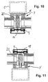
- top seal 3 for the post and the top seal can be used 3 'for the bolt then in the position shown in FIGS. 9 to 11 to be brought.
- An open hollow chamber 36 is located between the sealing walls 20 formed into the fasteners, e.g. a glass slide can be inserted can.
Landscapes
- Engineering & Computer Science (AREA)
- Architecture (AREA)
- Physics & Mathematics (AREA)
- Electromagnetism (AREA)
- Civil Engineering (AREA)
- Structural Engineering (AREA)
- Securing Of Glass Panes Or The Like (AREA)
- Load-Bearing And Curtain Walls (AREA)
- Specific Sealing Or Ventilating Devices For Doors And Windows (AREA)
Abstract
Description
- Fig. 1
- einen horizontalen Schnitt durch eine Pfosten-/Riegel-Konstruktion;
- Fig. 2
- einen senkrechten Schnitt durch die Pfosten-/Riegel-Konstruktion der Fig. 1;
- Fig. 3
- eine schematische Ansicht des Kreuzungsbereiches der Dichtungen für eine Pfosten-/Riegel-Konstruktion nach Art der Fig. 1;
- Fig. 4
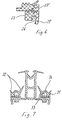
- einen Schnitt durch eine Aufsatzdichtung für den Pfosten;
- Fig. 5
- einen Schnitt durch eine Aufsatzdichtung für den Riegel;
- Fig. 6
- eine Ausschnittsvergrößerung aus Fig. 5;
- Fig. 7
- eine weitere Variante einer Aufsatzdichtung;
- Fig. 8
- einen Schnitt durch eine Aufsatzdichtung gemäß einem weiteren Ausführungsbeispiel in der Lagerposition;
- Fig. 9
- einen Schnitt durch die Aufsatzdichtung der Fig. 8 im Montagezustand;
- Fig. 10
- einen Schnitt durch eine Pfosten-/Riegel-Konstruktion, und
- Fig. 11
- einen Schnitt durch die Pfosten-/Riegel-Konstruktion mit einer Aufsatzdichtung für einen Riegel.
- 1
- Stahlprofil
- 2
- Aufsatzprofil
- 3
- Aufsatzdichtung (Pfosten)
- 3'
- Aufsatzdichtung (Riegel)
- 3a
- Grundsteg
- 3b
- Quersteg
- 4
- Glasanlagedichtung
- 5
- Füllung
- 6
- Klemmprofil
- 7
- Deckschale
- 8
- Schraube
- 9
- Dichtlippen
- 10
- Kammer
- 11
- Kammer/Entwässerungsnut
- 12
- Hohlkammer
- 13
- Hohlkammer
- 14
- Hohlkammer, Führungs- oder Rastnut
- 14a, b
- Nutstege
- 15
- Dichtungssteg
- 16
- Glasanlage
- 18
- Zentriernut
- 18a
- Nutsteg
- 19
- Scharnier
- 20
- Dichtungswand
- 21
- Rastunterteil
- 22
- Verbindungssteg
- 23
- Feder
- 23'
- Nut
- 24
- Rastnut
- 25
- Schenkel
- 26
- Quersteg
- 27
- Quersteg
- 28
- Hohlraum
- 29
- Quersteg
- 30
- Quersteg
- 31
- Glasanlagedichtung
- 32
- Dichtlippen
- 33
- Hohlraum
- 34
- Auflagebereich
- 35
- Scharnier
- 36
- Hohlkammer
- Δ
- Anlagewinkel
Claims (17)
- Aufsatzdichtung für eine Pfosten-/Riegel-Konstruktion, insbesondere für eine Pfosten-/Riegel-Konstruktion mit einem Statikprofil (1), auf dem ein Aufsatz- bzw. Adapterprofil (2) anbringbar ist, wobei die Aufsatzdichtung im wesentlichen im Querschnitt eine T-Form mit einem Grundsteg (3a) und zwei sich beidseits des Grundsteges (3a) im wesentlichen senkrecht zum Grundsteg erstrekkenden Querstegen (3b, 3c) aufweist, dadurch gekennzeichnet, daß der Grundsteg (3a) jeweils über wenigstens ein Scharnier (19) mit den Querstegen (3b, 3c) verbunden ist.
- Aufsatzdichtung nach Anspruch 1, dadurch gekennzeichnet, daß die Scharniere (19) als Filmscharniere ausgebildet sind.
- Aufsatzdichtung nach dem Oberbegriff des Anspruches 1 oder nach Anspruch 1, dadurch gekennzeichnet, daß sich der Grundsteg (3a) in einen Falzraum zwischen Füllungen (5) erstreckt und seitlich mit wenigstens einer Dichtlippe (9) versehen ist, die den Falzraum seitlich des Grundsteges 3a in mehrere Kammern (10, 11) unterteilt.
- Aufsatzdichtung nach einem der vorstehenden Ansprüche, dadurch gekennzeichnet, daß der Grundsteg (3a) mit geschlossenen oder einseitig offenen Hohlkammern (12,13,14,18) versehen ist.
- Aufsatzdichtung nach einem der vorstehenden Ansprüche, dadurch gekennzeichnet, daß im Bereich der Querstege (3b, 3c) eine geschlossene Basis vorgesehen ist, die abschnittsweise eine der Hohlkammern (12) begrenzt.
- Aufsatzdichtung nach einem der vorstehenden Ansprüche, dadurch gekennzeichnet, daß eine der Hohlkammern (13) als geschlossene Wärmeisolierungskammer ausgelegt ist.
- Aufsatzdichtung nach einem der vorstehenden Ansprüche, dadurch gekennzeichnet, daß eine der Hohlkammern (14, 18) als Führungs- oder Rastnut zur Zentrierung oder zum Einrasten weiterer Bauteile ausgelegt ist.
- Aufsatzdichtung nach dem Oberbegriff des Anspruches 1 oder nach einem der vorstehenden Ansprüche, dadurch gekennzeichnet, daß die Querstege (3b, 3c) der Aufsatzdichtungen (3, 3') eine Glasanlage (16) und ein Rastunterteil (21) aufweisen, die über ein Nut-Federsystem (23, 23') ineinander greifen.
- Aufsatzdichtung nach Anspruch 8, dadurch gekennzeichnet, daß die Glasanlage (16) oder das Rastunterteil (21) über einen Verbindungs-Dichtsteg (15) mit dem Grundsteg (3a) verbunden sind und daß die Nut (23') auf der Seite des Bauteiles (Glasanlage oder Rastunterteil) angeordnet ist, das über den Verbindungs-Dichtsteg (15) mit dem Grundsteg (3a) verbunden ist.
- Aufsatzdichtung nach Anspruch 8 oder 9, dadurch gekennzeichnet, daß die Glasanlage (16) und das Rastunterteil (21) vorzugsweise im äußeren Randbereich über einen scharnierartigen Verbindungssteg (22) direkt miteinander gekoppelt sind.
- Aufsatzdichtung nach einem der vorstehenden Ansprüche, dadurch gekennzeichnet, daß im Rastunterteil (21) eine Rastnut (24) ausgebildet ist, wobei ein äußere die Rastnut (24) begrenzender Schenkel (25) um einen Anlagewinkel (Δ) leicht nach innen geneigt ist.
- Aufsatzdichtung nach einem der vorstehenden Ansprüche, dadurch gekennzeichnet, daß der Grundsteg mit einem Quersteg (26 und 27) zur Positionierung der Aufsatzdichtung (3, 3') auf dem Aufsatzprofil versehen ist.
- Aufsatzdichtung nach einem der vorstehenden Ansprüche, dadurch gekennzeichnet, daß wenigstens einer der Querstege (26 und 27) lösbar, vorzugsweise über Sollbruchlinien, mit dem Grundsteg (3a) verbunden ist.
- Aufsatzdichtung nach einem der vorstehenden Ansprüche, dadurch gekennzeichnet, daß die Aufsatzdichtung (3, 3') mit einer Glasanlagedichtung (31) ausgebildet ist, dieser einen balligen mittleren Bereich (34), zwei relativ lange Dichtlippen (32) und einen Hohlraum (33) aufweist.
- Aufsatzdichtung nach einem der vorstehenden Ansprüche, dadurch gekennzeichnet, daß zwischen den Grundstegen (3a) eine offene Hohlkammer (36) ausgebildet ist.
- Aufsatzdichtung nach einem der vorstehenden Ansprüche, dadurch gekennzeichnet, daß die Dichtungswände (20) des Grundsteges (3a) über mindestens ein Scharnier (35) miteinander verbunden sind.
- Aufsatzdichtung nach einem der vorstehenden Ansprüche, dadurch gekennzeichnet, daß die Aufsatzdichtung als aufgefaltetes gestrecktes im wesentlichen flaches Profil hergestellt und aufgerollt transportierbar und lagerbar ist.
Applications Claiming Priority (2)
| Application Number | Priority Date | Filing Date | Title |
|---|---|---|---|
| DE10035772 | 2000-07-22 | ||
| DE10035772A DE10035772A1 (de) | 2000-07-22 | 2000-07-22 | Aufsatzdichtung für eine Pfosten-/Riegel-Konstruktion |
Publications (2)
| Publication Number | Publication Date |
|---|---|
| EP1174554A1 true EP1174554A1 (de) | 2002-01-23 |
| EP1174554B1 EP1174554B1 (de) | 2005-08-31 |
Family
ID=7649881
Family Applications (1)
| Application Number | Title | Priority Date | Filing Date |
|---|---|---|---|
| EP01117236A Expired - Lifetime EP1174554B1 (de) | 2000-07-22 | 2001-07-17 | Aufsatzdichtung für eine Pfosten-/Riegel-Konstruktion |
Country Status (4)
| Country | Link |
|---|---|
| EP (1) | EP1174554B1 (de) |
| AT (1) | ATE303478T1 (de) |
| DE (2) | DE10035772A1 (de) |
| ES (1) | ES2244527T3 (de) |
Cited By (7)
| Publication number | Priority date | Publication date | Assignee | Title |
|---|---|---|---|---|
| EP1505220A3 (de) * | 2003-08-06 | 2005-12-21 | Hermann Gutmann Werke AG | Aufsatzdichtung mit variabler Breite sowie Rahmenwerk |
| EP1529892A3 (de) * | 2003-11-07 | 2006-02-08 | Raico Bautechnik GmbH | Dichtung für eine Pfosten/Riegel-Konstruktion |
| FR2926312A1 (fr) * | 2008-01-16 | 2009-07-17 | En Economies Systemes Soc Resp | Installation composee d'une pluralite de panneaux et entretoise reliant deux panneaux successifs |
| NL2008320A (nl) * | 2011-02-18 | 2012-08-22 | Mini Flat | Dakbedekkingsysteem en werkwijze voor horizontaal meerlaags doorzichtig paneel op plat dak. |
| DE202013104191U1 (de) * | 2013-09-13 | 2014-12-16 | SCHÜCO International KG | Pfosten-Riegel-Konstruktion |
| CN113653202A (zh) * | 2021-09-01 | 2021-11-16 | 珠海华发城市研究院有限公司 | 一种新型的玻璃幕墙变形缝结构及安装方法 |
| US20230323729A1 (en) * | 2022-04-08 | 2023-10-12 | Arconic Technologies Llc | Collapsible element for façade systems |
Families Citing this family (3)
| Publication number | Priority date | Publication date | Assignee | Title |
|---|---|---|---|---|
| DE10319001B4 (de) * | 2003-04-25 | 2008-11-06 | Hermann Gutmann Werke Ag | Fassade oder Dach mit mehreren Entwässerungsebenen |
| DE102015121115A1 (de) | 2015-12-04 | 2017-06-08 | Hueck Gmbh & Co. Kg | Dichtung, sowie Pfosten-Riegel-Anordnung |
| CN111705981A (zh) * | 2020-07-05 | 2020-09-25 | 蔡冀奇 | 一种基于预防雨水侵蚀技术的石材幕墙 |
Citations (4)
| Publication number | Priority date | Publication date | Assignee | Title |
|---|---|---|---|---|
| DE19624629C1 (de) * | 1996-06-20 | 1997-12-11 | Neu Gmbh Geb | Abdichtsystem für Glasdächer und Glaswände |
| DE19741469A1 (de) * | 1997-09-19 | 1999-03-25 | Sommer Metallbau Stahlbau Gmbh | Vorrichtung zum Befestigen von Verglasungen, Fassaden oder dergleichen an einem Anschlußprofil |
| DE19901418A1 (de) | 1999-01-18 | 2000-07-20 | Schueco Int Kg | Im Falzraum einer Fassade oder eines Lichtdaches anzuordnendes Dichtungsprofil |
| EP1024233A1 (de) * | 1999-01-28 | 2000-08-02 | Röhm Gmbh | Verlegeprofilsystem für Platten |
-
2000
- 2000-07-22 DE DE10035772A patent/DE10035772A1/de not_active Withdrawn
-
2001
- 2001-07-17 DE DE50107257T patent/DE50107257D1/de not_active Expired - Lifetime
- 2001-07-17 AT AT01117236T patent/ATE303478T1/de active
- 2001-07-17 ES ES01117236T patent/ES2244527T3/es not_active Expired - Lifetime
- 2001-07-17 EP EP01117236A patent/EP1174554B1/de not_active Expired - Lifetime
Patent Citations (4)
| Publication number | Priority date | Publication date | Assignee | Title |
|---|---|---|---|---|
| DE19624629C1 (de) * | 1996-06-20 | 1997-12-11 | Neu Gmbh Geb | Abdichtsystem für Glasdächer und Glaswände |
| DE19741469A1 (de) * | 1997-09-19 | 1999-03-25 | Sommer Metallbau Stahlbau Gmbh | Vorrichtung zum Befestigen von Verglasungen, Fassaden oder dergleichen an einem Anschlußprofil |
| DE19901418A1 (de) | 1999-01-18 | 2000-07-20 | Schueco Int Kg | Im Falzraum einer Fassade oder eines Lichtdaches anzuordnendes Dichtungsprofil |
| EP1024233A1 (de) * | 1999-01-28 | 2000-08-02 | Röhm Gmbh | Verlegeprofilsystem für Platten |
Cited By (11)
| Publication number | Priority date | Publication date | Assignee | Title |
|---|---|---|---|---|
| EP1505220A3 (de) * | 2003-08-06 | 2005-12-21 | Hermann Gutmann Werke AG | Aufsatzdichtung mit variabler Breite sowie Rahmenwerk |
| EP1529892A3 (de) * | 2003-11-07 | 2006-02-08 | Raico Bautechnik GmbH | Dichtung für eine Pfosten/Riegel-Konstruktion |
| FR2926312A1 (fr) * | 2008-01-16 | 2009-07-17 | En Economies Systemes Soc Resp | Installation composee d'une pluralite de panneaux et entretoise reliant deux panneaux successifs |
| NL2008320A (nl) * | 2011-02-18 | 2012-08-22 | Mini Flat | Dakbedekkingsysteem en werkwijze voor horizontaal meerlaags doorzichtig paneel op plat dak. |
| BE1020084A5 (nl) * | 2011-02-18 | 2013-04-02 | Mini Flat | Dakbedekkingsysteem en werkwijze voor horizontaal meerlaags doorzichtig paneel op plat dak. |
| DE202013104191U1 (de) * | 2013-09-13 | 2014-12-16 | SCHÜCO International KG | Pfosten-Riegel-Konstruktion |
| CN105531429A (zh) * | 2013-09-13 | 2016-04-27 | 许克国际两合公司 | 竖框横梁结构 |
| CN105531429B (zh) * | 2013-09-13 | 2018-09-18 | 许克国际两合公司 | 竖框横梁结构 |
| CN113653202A (zh) * | 2021-09-01 | 2021-11-16 | 珠海华发城市研究院有限公司 | 一种新型的玻璃幕墙变形缝结构及安装方法 |
| US20230323729A1 (en) * | 2022-04-08 | 2023-10-12 | Arconic Technologies Llc | Collapsible element for façade systems |
| US12404715B2 (en) * | 2022-04-08 | 2025-09-02 | Arconic Technologies Llc | Collapsible element for façade systems |
Also Published As
| Publication number | Publication date |
|---|---|
| EP1174554B1 (de) | 2005-08-31 |
| DE50107257D1 (de) | 2005-10-06 |
| ATE303478T1 (de) | 2005-09-15 |
| DE10035772A1 (de) | 2002-01-31 |
| ES2244527T3 (es) | 2005-12-16 |
Similar Documents
| Publication | Publication Date | Title |
|---|---|---|
| EP0436868B1 (de) | Traggerippe für eine oder an einer Fassadenwand | |
| EP0100991A2 (de) | Verbundprofil | |
| DE19830087C2 (de) | Gebäudefassade oder Dachfassade mit einem Rahmenwerk aus Pfosten und Riegeln | |
| DE19901418A1 (de) | Im Falzraum einer Fassade oder eines Lichtdaches anzuordnendes Dichtungsprofil | |
| EP1174554B1 (de) | Aufsatzdichtung für eine Pfosten-/Riegel-Konstruktion | |
| EP1978171B1 (de) | Elementierte Pfosten-Riegel-Fassade | |
| CH677252A5 (de) | ||
| AT392311B (de) | Rahmenkonstruktion in pfosten-riegel-bauweise, insbesondere fuer fassaden, daecher, fensterwaende od. dgl. | |
| EP0569654A1 (de) | Alu-Holz-Verbundprofil für die Herstellung von Fenstern, daraus hergestelltes Fenster und Verfahren zur Herstellung eines solchen Fensters | |
| DE10223038A1 (de) | Fassadenkonstruktion mit einem durch ein Dichtelement abgedichteten Riegelseitigen Isolierprofil | |
| EP0221480B1 (de) | Fassadenwand | |
| DE2927463A1 (de) | Fassadenwand | |
| DE3420224A1 (de) | Fenster aus vorgefertigten einzelteilen und verfahren zu dessen herstellung | |
| EP3543450B1 (de) | Hebeschiebetür-/schiebetür-profilsystem | |
| DE19953675B4 (de) | Kreuzstoßverbindung | |
| EP1836359A1 (de) | Modulare fassade für gebäude, glasauflagedichtung und schraube | |
| DE10319001A1 (de) | Fassade oder Dach mit mehreren Entwässerungsebenen | |
| DE9414887U1 (de) | Vorrichtung zur Befestigung von Platten an Fassaden | |
| DE202005000604U1 (de) | Dichtungsanordnung für Fassaden oder Lichtdächer | |
| WO2002029174A1 (de) | Im glasfalz einer fassade oder eines lichtdaches vorgesehene trägereinheit | |
| DE19803984C2 (de) | Fassadenkonstruktion für polygonzugartigen Grundriß | |
| DE29812552U1 (de) | Zargenkonstruktion | |
| DE9206375U1 (de) | Tragwerk für Glasfassaden, -wände und/oder -dächer | |
| EP3907340B1 (de) | Dichtungsprofil und pfosten-riegel-konstruktion | |
| DE4325121A1 (de) | Panzer für Rolltore, Rolläden, Jalousien o. dgl. |
Legal Events
| Date | Code | Title | Description |
|---|---|---|---|
| PUAI | Public reference made under article 153(3) epc to a published international application that has entered the european phase |
Free format text: ORIGINAL CODE: 0009012 |
|
| AK | Designated contracting states |
Kind code of ref document: A1 Designated state(s): AT BE CH CY DE DK ES FI FR GB GR IE IT LI LU MC NL PT SE TR |
|
| AX | Request for extension of the european patent |
Free format text: AL;LT PAYMENT 20010717;LV PAYMENT 20010717;MK PAYMENT 20010717;RO;SI PAYMENT 20010717 |
|
| 17P | Request for examination filed |
Effective date: 20020124 |
|
| AKX | Designation fees paid |
Free format text: AT BE CH CY DE DK ES FI FR GB GR IE IT LI LU MC NL PT SE TR |
|
| AXX | Extension fees paid |
Free format text: LT PAYMENT 20010717;LV PAYMENT 20010717;MK PAYMENT 20010717;SI PAYMENT 20010717 |
|
| 17Q | First examination report despatched |
Effective date: 20030528 |
|
| GRAP | Despatch of communication of intention to grant a patent |
Free format text: ORIGINAL CODE: EPIDOSNIGR1 |
|
| GRAS | Grant fee paid |
Free format text: ORIGINAL CODE: EPIDOSNIGR3 |
|
| GRAA | (expected) grant |
Free format text: ORIGINAL CODE: 0009210 |
|
| AK | Designated contracting states |
Kind code of ref document: B1 Designated state(s): AT BE CH CY DE DK ES FI FR GB GR IE IT LI LU MC NL PT SE TR |
|
| AX | Request for extension of the european patent |
Extension state: LT LV MK SI |
|
| PG25 | Lapsed in a contracting state [announced via postgrant information from national office to epo] |
Ref country code: IE Free format text: LAPSE BECAUSE OF FAILURE TO SUBMIT A TRANSLATION OF THE DESCRIPTION OR TO PAY THE FEE WITHIN THE PRESCRIBED TIME-LIMIT Effective date: 20050831 Ref country code: IT Free format text: LAPSE BECAUSE OF FAILURE TO SUBMIT A TRANSLATION OF THE DESCRIPTION OR TO PAY THE FEE WITHIN THE PRESCRIBED TIME-LIMIT;WARNING: LAPSES OF ITALIAN PATENTS WITH EFFECTIVE DATE BEFORE 2007 MAY HAVE OCCURRED AT ANY TIME BEFORE 2007. THE CORRECT EFFECTIVE DATE MAY BE DIFFERENT FROM THE ONE RECORDED. Effective date: 20050831 Ref country code: FI Free format text: LAPSE BECAUSE OF FAILURE TO SUBMIT A TRANSLATION OF THE DESCRIPTION OR TO PAY THE FEE WITHIN THE PRESCRIBED TIME-LIMIT Effective date: 20050831 |
|
| REG | Reference to a national code |
Ref country code: CH Ref legal event code: EP Ref country code: GB Ref legal event code: FG4D Free format text: NOT ENGLISH |
|
| REG | Reference to a national code |
Ref country code: CH Ref legal event code: NV Representative=s name: KATZAROV S.A. |
|
| REG | Reference to a national code |
Ref country code: IE Ref legal event code: FG4D Free format text: LANGUAGE OF EP DOCUMENT: GERMAN |
|
| REF | Corresponds to: |
Ref document number: 50107257 Country of ref document: DE Date of ref document: 20051006 Kind code of ref document: P |
|
| GBT | Gb: translation of ep patent filed (gb section 77(6)(a)/1977) |
Effective date: 20050929 |
|
| PG25 | Lapsed in a contracting state [announced via postgrant information from national office to epo] |
Ref country code: SE Free format text: LAPSE BECAUSE OF FAILURE TO SUBMIT A TRANSLATION OF THE DESCRIPTION OR TO PAY THE FEE WITHIN THE PRESCRIBED TIME-LIMIT Effective date: 20051130 Ref country code: GR Free format text: LAPSE BECAUSE OF FAILURE TO SUBMIT A TRANSLATION OF THE DESCRIPTION OR TO PAY THE FEE WITHIN THE PRESCRIBED TIME-LIMIT Effective date: 20051130 Ref country code: DK Free format text: LAPSE BECAUSE OF FAILURE TO SUBMIT A TRANSLATION OF THE DESCRIPTION OR TO PAY THE FEE WITHIN THE PRESCRIBED TIME-LIMIT Effective date: 20051130 |
|
| REG | Reference to a national code |
Ref country code: ES Ref legal event code: FG2A Ref document number: 2244527 Country of ref document: ES Kind code of ref document: T3 |
|
| PG25 | Lapsed in a contracting state [announced via postgrant information from national office to epo] |
Ref country code: PT Free format text: LAPSE BECAUSE OF FAILURE TO SUBMIT A TRANSLATION OF THE DESCRIPTION OR TO PAY THE FEE WITHIN THE PRESCRIBED TIME-LIMIT Effective date: 20060222 |
|
| LTIE | Lt: invalidation of european patent or patent extension |
Effective date: 20050831 |
|
| REG | Reference to a national code |
Ref country code: IE Ref legal event code: FD4D |
|
| ET | Fr: translation filed | ||
| PLBE | No opposition filed within time limit |
Free format text: ORIGINAL CODE: 0009261 |
|
| STAA | Information on the status of an ep patent application or granted ep patent |
Free format text: STATUS: NO OPPOSITION FILED WITHIN TIME LIMIT |
|
| PG25 | Lapsed in a contracting state [announced via postgrant information from national office to epo] |
Ref country code: MC Free format text: LAPSE BECAUSE OF NON-PAYMENT OF DUE FEES Effective date: 20060731 |
|
| 26N | No opposition filed |
Effective date: 20060601 |
|
| PG25 | Lapsed in a contracting state [announced via postgrant information from national office to epo] |
Ref country code: LU Free format text: LAPSE BECAUSE OF NON-PAYMENT OF DUE FEES Effective date: 20060717 Ref country code: TR Free format text: LAPSE BECAUSE OF FAILURE TO SUBMIT A TRANSLATION OF THE DESCRIPTION OR TO PAY THE FEE WITHIN THE PRESCRIBED TIME-LIMIT Effective date: 20050831 |
|
| PG25 | Lapsed in a contracting state [announced via postgrant information from national office to epo] |
Ref country code: CY Free format text: LAPSE BECAUSE OF FAILURE TO SUBMIT A TRANSLATION OF THE DESCRIPTION OR TO PAY THE FEE WITHIN THE PRESCRIBED TIME-LIMIT Effective date: 20050831 |
|
| PGFP | Annual fee paid to national office [announced via postgrant information from national office to epo] |
Ref country code: CH Payment date: 20110725 Year of fee payment: 11 |
|
| PGFP | Annual fee paid to national office [announced via postgrant information from national office to epo] |
Ref country code: GB Payment date: 20120723 Year of fee payment: 12 |
|
| PGFP | Annual fee paid to national office [announced via postgrant information from national office to epo] |
Ref country code: FR Payment date: 20120803 Year of fee payment: 12 Ref country code: BE Payment date: 20120724 Year of fee payment: 12 Ref country code: ES Payment date: 20120723 Year of fee payment: 12 |
|
| PGFP | Annual fee paid to national office [announced via postgrant information from national office to epo] |
Ref country code: NL Payment date: 20120718 Year of fee payment: 12 |
|
| PGFP | Annual fee paid to national office [announced via postgrant information from national office to epo] |
Ref country code: AT Payment date: 20120720 Year of fee payment: 12 |
|
| BERE | Be: lapsed |
Owner name: *SCHUCO INTERNATIONAL K.G. Effective date: 20130731 |
|
| REG | Reference to a national code |
Ref country code: NL Ref legal event code: V1 Effective date: 20140201 |
|
| REG | Reference to a national code |
Ref country code: CH Ref legal event code: PL |
|
| REG | Reference to a national code |
Ref country code: AT Ref legal event code: MM01 Ref document number: 303478 Country of ref document: AT Kind code of ref document: T Effective date: 20130717 |
|
| GBPC | Gb: european patent ceased through non-payment of renewal fee |
Effective date: 20130717 |
|
| REG | Reference to a national code |
Ref country code: FR Ref legal event code: ST Effective date: 20140331 |
|
| PG25 | Lapsed in a contracting state [announced via postgrant information from national office to epo] |
Ref country code: LI Free format text: LAPSE BECAUSE OF NON-PAYMENT OF DUE FEES Effective date: 20130731 Ref country code: NL Free format text: LAPSE BECAUSE OF NON-PAYMENT OF DUE FEES Effective date: 20140201 Ref country code: BE Free format text: LAPSE BECAUSE OF NON-PAYMENT OF DUE FEES Effective date: 20130731 Ref country code: CH Free format text: LAPSE BECAUSE OF NON-PAYMENT OF DUE FEES Effective date: 20130731 Ref country code: GB Free format text: LAPSE BECAUSE OF NON-PAYMENT OF DUE FEES Effective date: 20130717 |
|
| PG25 | Lapsed in a contracting state [announced via postgrant information from national office to epo] |
Ref country code: FR Free format text: LAPSE BECAUSE OF NON-PAYMENT OF DUE FEES Effective date: 20130731 Ref country code: AT Free format text: LAPSE BECAUSE OF NON-PAYMENT OF DUE FEES Effective date: 20130717 |
|
| REG | Reference to a national code |
Ref country code: ES Ref legal event code: FD2A Effective date: 20140908 |
|
| PGFP | Annual fee paid to national office [announced via postgrant information from national office to epo] |
Ref country code: DE Payment date: 20140728 Year of fee payment: 14 |
|
| PG25 | Lapsed in a contracting state [announced via postgrant information from national office to epo] |
Ref country code: ES Free format text: LAPSE BECAUSE OF NON-PAYMENT OF DUE FEES Effective date: 20130718 |
|
| REG | Reference to a national code |
Ref country code: DE Ref legal event code: R119 Ref document number: 50107257 Country of ref document: DE |
|
| PG25 | Lapsed in a contracting state [announced via postgrant information from national office to epo] |
Ref country code: DE Free format text: LAPSE BECAUSE OF NON-PAYMENT OF DUE FEES Effective date: 20160202 |