EP1174170A2 - Filter - Google Patents
Filter Download PDFInfo
- Publication number
- EP1174170A2 EP1174170A2 EP01117298A EP01117298A EP1174170A2 EP 1174170 A2 EP1174170 A2 EP 1174170A2 EP 01117298 A EP01117298 A EP 01117298A EP 01117298 A EP01117298 A EP 01117298A EP 1174170 A2 EP1174170 A2 EP 1174170A2
- Authority
- EP
- European Patent Office
- Prior art keywords
- filter
- filter member
- convexo
- concaves
- face
- Prior art date
- Legal status (The legal status is an assumption and is not a legal conclusion. Google has not performed a legal analysis and makes no representation as to the accuracy of the status listed.)
- Granted
Links
Images


Classifications
-
- B—PERFORMING OPERATIONS; TRANSPORTING
- B01—PHYSICAL OR CHEMICAL PROCESSES OR APPARATUS IN GENERAL
- B01D—SEPARATION
- B01D35/00—Filtering devices having features not specifically covered by groups B01D24/00 - B01D33/00, or for applications not specifically covered by groups B01D24/00 - B01D33/00; Auxiliary devices for filtration; Filter housing constructions
- B01D35/02—Filters adapted for location in special places, e.g. pipe-lines, pumps, stop-cocks
- B01D35/027—Filters adapted for location in special places, e.g. pipe-lines, pumps, stop-cocks rigidly mounted in or on tanks or reservoirs
- B01D35/0273—Filtering elements with a horizontal or inclined rotation or symmetry axis submerged in tanks or reservoirs
-
- B—PERFORMING OPERATIONS; TRANSPORTING
- B01—PHYSICAL OR CHEMICAL PROCESSES OR APPARATUS IN GENERAL
- B01D—SEPARATION
- B01D27/00—Cartridge filters of the throw-away type
- B01D27/04—Cartridge filters of the throw-away type with cartridges made of a piece of unitary material, e.g. filter paper
- B01D27/06—Cartridge filters of the throw-away type with cartridges made of a piece of unitary material, e.g. filter paper with corrugated, folded or wound material
-
- F—MECHANICAL ENGINEERING; LIGHTING; HEATING; WEAPONS; BLASTING
- F02—COMBUSTION ENGINES; HOT-GAS OR COMBUSTION-PRODUCT ENGINE PLANTS
- F02M—SUPPLYING COMBUSTION ENGINES IN GENERAL WITH COMBUSTIBLE MIXTURES OR CONSTITUENTS THEREOF
- F02M37/00—Apparatus or systems for feeding liquid fuel from storage containers to carburettors or fuel-injection apparatus; Arrangements for purifying liquid fuel specially adapted for, or arranged on, internal-combustion engines
- F02M37/22—Arrangements for purifying liquid fuel specially adapted for, or arranged on, internal-combustion engines, e.g. arrangements in the feeding system
- F02M37/32—Arrangements for purifying liquid fuel specially adapted for, or arranged on, internal-combustion engines, e.g. arrangements in the feeding system characterised by filters or filter arrangements
- F02M37/34—Arrangements for purifying liquid fuel specially adapted for, or arranged on, internal-combustion engines, e.g. arrangements in the feeding system characterised by filters or filter arrangements by the filter structure, e.g. honeycomb, mesh or fibrous
-
- F—MECHANICAL ENGINEERING; LIGHTING; HEATING; WEAPONS; BLASTING
- F02—COMBUSTION ENGINES; HOT-GAS OR COMBUSTION-PRODUCT ENGINE PLANTS
- F02M—SUPPLYING COMBUSTION ENGINES IN GENERAL WITH COMBUSTIBLE MIXTURES OR CONSTITUENTS THEREOF
- F02M37/00—Apparatus or systems for feeding liquid fuel from storage containers to carburettors or fuel-injection apparatus; Arrangements for purifying liquid fuel specially adapted for, or arranged on, internal-combustion engines
- F02M37/22—Arrangements for purifying liquid fuel specially adapted for, or arranged on, internal-combustion engines, e.g. arrangements in the feeding system
- F02M37/32—Arrangements for purifying liquid fuel specially adapted for, or arranged on, internal-combustion engines, e.g. arrangements in the feeding system characterised by filters or filter arrangements
- F02M37/50—Filters arranged in or on fuel tanks
Definitions
- the invention relates to the structure of a filter and, more particularly, to the structure of an in-tank type fuel filter installed in a vehicular fuel tank.
- Fig. 16 shows a fuel tank 1 installed in a vehicle.
- a fuel pump 3 for delivering fuel to a fuel injection system 4 is disposed in the fuel tank 1.
- a fuel filter 2 is attached to the fuel pump 3 at its upstream inlet via a coupling member 7.
- Fig. 17 shows details of the fuel filter 2.
- the fuel filter 2 is coupled with the fuel pump 3 via the coupling member 7, and abuts at the other end thereof on a bottom wall 9 of the fuel tank 1. Thus, even if the fuel level has decreased, a sufficient amount of fuel can be pumped up.
- the fuel filter 2 is composed of a filter member 5 constructed of a mesh screen made from a synthetic resin and having a multitude of apertures formed therein, and of a protector 6 disposed inside the filter member 5.
- the protector 6 is made from a synthetic resin, offers a communication passage leading to the fuel pump 3, and prevents cohesion of the filter member 5.
- the in-tank type fuel filter 2 as described above has the protector 6 inside, it is advantageous in that cohesion of the filter member 5 can be prevented, that a sufficient inner space 8 can be ensured, and that the fuel filter 2 can be installed with the filter member 5 pressed onto the bottom wall 9 of the fuel tank 1.
- the fuel filter 2 has the following problems.
- the filter member 5 is apt to be abraded and thus is disadvantageous in terms of durability. Further, vibrations of the pump are conveyed via the protector 6 and cause discomfort to human bodies as harmful noise.
- the protector 6 since a molded article made from a synthetic resin is used as the protector 6, the protector 6 tends toward deformation such as warp when soaked in fuel.
- the filter member 5 is also deformed simultaneously with the deformation of the protector 6, and decreases in durability as a result.
- a corner portion of the protector 6 abrades the filter member 5 at a portion that is in contact with the bottom wall 9 of the fuel tank 1. This threatens to accelerate abrasion of the filter member 5 and make it useless.
- the mesh screen of the related art is planar, the filtration area is limited even if it is used.
- the filter is inevitably enlarged if an attempt has been made to increase the filtration area and prolong the period of endurance.
- a filter comprising a filter member forming at least two opposed faces, an inner space surrounded by the filter member for accumulation of a liquid, and a coupling member establishing communication between the inner space and the outside to deliver the liquid in the inner space to the outside, wherein the liquid is removed of foreign matters by passing through the filter member and is discharged via the coupling member.
- a plurality of convexo-concaves are provided on at least one face of the filter member. Due to this construction, even though the protector has been dispensed with, a sufficient inner space can be guaranteed and the filtration area can be increased.
- Figs. 1 to 3 show the filter according to the embodiment 1 of the invention.
- Fig. 1 is a cross-sectional view of the filter.
- Fig. 2 is a cross-sectional view along the line II-II shown in Fig. 1.
- Fig. 3 is a plan view of the filter.
- a fuel filter 10 which is generally oblong in a plan view, is coupled with a fuel pump on its upstream side via a coupling member 13.
- the fuel pump is disposed in a fuel tank.
- the fuel filter 10 is composed of an upper filter member 11 and a lower filter member 12.
- the filter members 11, 12 are made from filter paper, a non-woven fabric or the like. Peripheral portions 30 of the filter members 11, 12 are welded by a thermal welding means such as ultrasonic welding or electro-deposition or are glued by adhesives or the like, so that inner spaces 14 are formed inside the filter members 11, 12.
- a plurality of convexo-concaves 15, 16 are formed e.g. by bending the filter members 11, 12.
- inner leading ends 15', 16' of the convexo-concaves 15, 16 abut on each other.
- the inner leading ends 15', 16' are linear in a plan view and intersect with each other while being offset from each other by 90°.
- the inner leading ends 15', 16' of the convexo-concaves 15, 16 may simply abut on each other, they may be connected by thermal welding, adhesives or the like for the purpose of increasing rigidity. Note that the term "joint" in the present specification covers the concepts of simple abutment, connection by thermal welding, and so on.
- a convexo-concave-less central inner space 14' is formed in a central portion of the upper filter member 11.
- the coupling member 13 is connected with the upper filter member 11 in the central inner space 14' by thermal welding, adhesives or the like.
- the coupling member 13 is coupled at the other end thereof with the fuel pump.
- the upper filter member 11 is provided with a convexo-concave-less band-shaped passage 33 that extends in the longitudinal direction of the oblong, i.e., perpendicularly to the convexo-concave direction and that is symmetric with respect to the coupling member 13.
- the inner spaces 14 formed by the convex portions 15 of the upper filter member 11 communicate with the band-shaped passage 33.
- the inner spaces 14 formed by the convex portions 15 of the upper filter member 11 also communicate with the inner spaces formed by the convex portions 16 of the lower filter member 16. Fuel that has entered the filter from the upper filter member 11 is delivered to the central inner space 14' via the band-shaped passage 33 and the lower inner spaces.
- the lower filter member 12 is provided with the convex portions 16 extending in the longitudinal direction of the oblong.
- the inner spaces 14 formed by the convex portions 16 communicate with the central inner space 14' at the center of the filter. Therefore, fuel that has entered the filter from the lower filter member 12 flows to the central inner space 14' through the inner spaces formed by the lower filter member. A part of the fuel is delivered to the central inner space 14' via the inner spaces 14 of the upper filter member.
- the band-shaped passage 33 also serves to prevent air from accumulating in the inner spaces.
- the angle of intersection can be reduced within such a range that all the fuel that has entered the filter can flow to the central inner space 14' with which the coupling member 13 is coupled.
- the inner and outer leading ends 15', 16' of the convexo-concaves 15, 16 are linear in a plan view, they may be curved or zigzag.
- the filter members may not necessarily be oblong and may be square, circular and so on.
- the non-woven fabric is preferably the mixture of a raw fiber made from polyester, polypropylene, rayon, glass, acetate or the like and an adhesive fiber made from polyester, polypropylene, rayon, glass, acetate or the like.
- the adhesive fiber is surface-coated with a low-boiling resin such as modified polyester, modified polyethylene, modified polypropylene or the like.
- the fuel filter 10 is robust even though it is made only from filter paper or a non-woven fabric. Further, the surface area of the fuel filter 10 can be enlarged by providing a plurality of convexo-concaves. Also, since the convexo-concaves guarantee sufficient inner spaces, fuel that has entered the inner spaces 14 from the entire filter members 11, 12 flow smoothly to the central inner space 14'. As a result, the intake efficiency of the fuel pump can be enhanced.
- buffer agents 35 composed of coagulated adhesives, plates and so on are provided on the outer leading ends of the convexo-concaves of the lower filter member 12 as shown in Fig. 2.
- Figs. 4 and 5 show the filter according to the embodiment 2 of the invention.
- Fig. 4 is a cross-sectional view along a line IV-IV shown in Fig. 5.
- Fig. 5 is a plan view.
- the embodiment 2 employs a plurality of dimples instead of the convexo-concaves of the embodiment 1. In other respects, the embodiment 2 is identical with the embodiment 1.
- a plurality of dimples 17, 18 as conical recesses are formed e.g. by pressing a tang onto flat-sheet filter members made from filter paper, a non-woven fabric or the like.
- the oblong filter members are used as the upper and lower filter members 11, 12.
- One of the filter members 11 (12) is superposed on the other filter member 12 (11) such that leading ends 17' (18') of the dimples 17 (18) of the one of the filter members 11 (12) abut on an inner surface of the other filter member 12 (11). If occasion demands, the abutment portions as well as the peripheral portions 30 are connected by thermal welding, adhesives or the like.
- Figs. 6 and 7 are cross-sectional views of the filter according to the embodiment 3 of the invention.
- the embodiment 3 although a plurality of dimples are provided as is the case with the embodiment 2, a plurality of dimples are provided only on one of the filter members. In other respects, the embodiment 3 is identical with the embodiment 2.
- the upper filter member 11 is provided with a plurality of dimples 17, and leading ends 17' of the dimples 17 abut on an inner surface of the lower filter member 12. If occasion demands, the abutment portions and the peripheral portions 30 are connected by thermal welding, adhesives or the like.
- the lower filter member 12 is provided with a plurality of dimples 18, and leading ends 18' of the dimples 18 abut on an inner surface of the upper filter member 11. If occasion demands, the abutment portions as well as the peripheral portions 30 are connected by thermal welding, adhesives or the like.
- the filter of the embodiment shown in Figs. 6 and 7 is slightly less robust than that of the embodiment 2, the inner spaces can be widened.
- Figs. 8 and 9 show the filter according to the embodiment 4 of the invention.
- Fig. 8 is a cross-sectional view along a line VIII-VIII shown in Fig. 9.
- Fig. 9 is a plan view.
- the embodiment 4 although a plurality of dimples are provided as is the case with the embodiment 2, the abutment portions of the leading ends of the dimples are different from those of the embodiment 2. In other respects, the embodiment 4 is identical with the embodiment 2.
- the upper and lower filter members 11, 12 are respectively provided with the same number of dimples 17, 18 of the same shape substantially at the same positions, and the leading ends 17', 18' of the dimples 17, 18 abut on each other. If occasion demands, the abutment portions as well as the peripheral portions 30 are connected by thermal welding, adhesives or the like.
- the filter 10 has been increased in height due to such a construction, the inner spaces 14 can be widened in comparison with the embodiments 2 and 3.
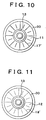
- Figs. 10 and 11 are plan views of the filter according to the embodiment 5 of the invention.
- the upper and lower filter members 11, 12 are in the shape of a circle stretching generally around the coupling member 13, and at least one of the filter members 11, 12 is provided with a plurality of radially extending convexo-concaves.
- the upper and lower filter members 11, 12 are generally in the same shape, i.e., in a circular shape.
- the coupling member 13 is disposed at the central portion of the circle.
- a plurality of radially extending convexo-concaves are formed only in the upper filter member 11.
- the inner leading ends 17' of the convexo-concaves formed in the upper filter member 11 abut on the inner surface of the lower filter member as is the case with the embodiments shown in Figs. 4 and 6. If occasion demands, the inner leading ends 17' are connected by thermal welding, adhesives or the like.
- the peripheral portions 30 are connected by thermal welding or the like.
- the upper and lower filter members 11, 12 are generally in the same shape, i.e., in a circular shape.
- the coupling member 13 is disposed at the central portion of the circle.
- a plurality of radially extending convexo-concaves are formed only in the lower filter member 12.
- the inner leading ends 18' of the convexo-concaves formed in the lower filter member 12 abut on the inner surface of the upper filter member 11 as is the case with the embodiments shown in Figs. 4 and 7. If occasion demands, the inner leading ends 18' are connected by thermal welding, adhesives or the like.
- the peripheral portions 30 are connected by thermal welding or the like.
- both the upper and lower filter members 11, 12 may be provided with the same number of convexo-concaves of the same shape substantially at the same positions, and the inner leading ends 17', 18' of the convexo-concaves may abut on each other.
- both the filter members may not necessarily be circular and may be square, oblong or in a shape suited for attachment to the fuel tank.
- Fig. 12 is a cross-sectional view of the filter according to the embodiment 6 of the invention.
- the embodiment 6 is characterized in that one filter member is folded back and stuck. In other respects, the embodiment 6 is identical with the embodiment 1.
- one oblong filter member is folded back along a central fold-back portion 31 thereof, and the peripheral portions 30 of the other three sides are welded by a thermal welding means such as ultrasonic welding or electro-deposition so that the filter 10 having the inner spaces 14 inside is formed.
- convexo-concaves are formed in advance in locations corresponding to the upper and lower filter members 11, 12, and the convexo-concaves formed in the upper filter member 11 and the convexo-concaves formed in the lower filter member 12 intersect with each other while being offset from each other by 90° as is the case with the embodiment 1. Furthermore, the convexo-concave-less central inner space 14' is formed in the central portion of the upper filter member 11.
- the coupling member 13 is coupled with the central inner space 14', and the convexo-concave-less band-shaped passages 33 are formed in the longitudinal direction of the upper filter member 11 as is the case with the embodiment 1.
- the embodiment 6 is also applicable to a filter having the dimples 17 shown in Figs. 4 to 9 instead of the convexo-concaves.
- Such a construction makes it possible to easily assemble the filter 10 and reduce the manufacturing costs thereof.
- Fig. 13 is a cross-sectional view of the filter according to the embodiment 7 of the invention.
- the embodiment 7 is characterized in that one filter member is folded back and stuck and that the coupling member 13 is disposed at the stuck portion of the filter member.
- the filter member is the same as that of the embodiment 1.
- one oblong filter member is folded back along the central fold-back portion 31 thereof, and the peripheral portions 30 of the other three sides are welded by a thermal welding means such as ultrasonic welding or electro-deposition so that the filter 10 having the inner spaces 14 inside is formed.
- convexo-concaves are formed in advance in locations corresponding to the upper and lower filter members 11, 12, and the convexo-concaves formed in the upper filter member 11 and the convexo-concaves formed in the lower filter member 12 intersect with each other while being offset from each other by 90°. Furthermore, the convexo-concave-less band-shaped passage 33 is formed in the longitudinal direction of the upper filter member 11.
- An opening 32 for connecting the coupling member 13 is made in the fold-back portion 31.
- the coupling member 13 is inserted into the opening 32 and is connected by thermal welding, adhesives or the like.
- the embodiment 7 is also applicable to a filter having the dimples 17 shown in Figs. 4 to 9 instead of the convexo-concaves.
- Such a construction makes it possible to easily assemble the filter 10, easily mount the coupling member 13 on the filter 10, and further reduce the manufacturing costs thereof.
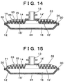
- Figs. 14 and 15 are cross-sectional views of the filter according to the embodiment 8 of the invention.
- filter members are made from a non-woven fabric and a mesh screen 34 is stuck on outer surfaces of the filter members.
- the embodiment 8 is identical with the embodiment 1.
- the mixture of a raw fiber and an adhesive fiber that is surface-coated with a low-boiling resin is preferably used as a non-woven fabric from which the filter members are made.
- a non-woven fabric made from such substances is used, sufficient durability is not always guaranteed.
- a reinforcing material and the mesh screen 34 having a filtering function are stuck on the surface of the non-woven fabric.
- the convexo-concaves 15, 16 are formed, and the upper and lower filter members 11, 12 are made and superposed on each other such that the convexo-concaves 15, 16 intersect with each other while being offset from each other by 90°.
- the inner leading ends 15', 16' of the convexo-concaves, i.e., the abutment portions of the filter members 11, 12 as well as the peripheral portions 30 are connected by thermal welding or the like.
- the mesh screen 34 may be a synthetic resin that has been coarsely woven for the sake of porosity or a thin flat plate having a multitude of apertures.
- the convexo-concave-less band-shaped passage 33 is formed in the longitudinal direction of the upper filter member 11 as is the case with the embodiment 1.
- the filter members are made from a non-woven fabric, and the mesh screen 34 is connected only with the outer surface of the lower filter member 12.
- the convexo-concaves 15, 16 are formed in the upper and lower filter members 11, 12 and superposed on each other while being offset from each other by 90° as is the case with the embodiment 1.
- the filter members 11, 12 as well as the peripheral portions 30 are connected by thermal welding or the like.
- the mesh screen 34 is superposed on the outer surface of the lower filter member 12 so that the mesh screen 34 is also connected simultaneously with the thermal welding of the peripheral portions 30.
- the convexo-concave band-shaped passage 33 is formed in the longitudinal direction of the upper filter member 11 as is the case with the embodiment 1.
- Such a construction makes it possible to suppress abrasion especially on the outer surface of the lower filter member 12 abutting on the bottom wall of the fuel tank and increase durability thereof.
- the filter of the invention is composed of a filter member forming at least two opposed faces, an inner space surrounded by the filter member for accumulation of a liquid, and a coupling member establishing communication between the inner space and the outside to deliver the liquid in the inner space to the outside.
- the liquid is removed of foreign matters by passing through the filter member and is discharged via the coupling member.
- a plurality of convexo-concaves are provided on at least one face of the filter member.
- the leading ends of the convexo-concaves on the one face of the filter member are formed generally linearly in a plan view. Because a sufficient inner space can be formed and the filtration area can be increased due to this construction, the intake efficiency of the fuel pump can be enhanced.
- linear leading ends may radially stretch around the coupling member. According to this construction, because fuel and air in the inner space flow smoothly toward the coupling member and especially because air does not dwell inside, the intake efficiency of the fuel pump can further be enhanced.
- the convexo-concaves of the filter member may be dimples, and the leading ends of the dimples may be jointed with the other inner surface of the filter member or may be jointed with each other.
- the dimples are made for example by pressing protrusions onto the surfaces of flat-shaped filter member, whereby the manufacture thereof can be facilitated in comparison with the filter member that is bent to form convexo-concaves.
- two filter members may be connected or one filter member may be folded back and connected. This construction makes it possible to easily manufacture the filter and reduce the costs thereof.
- the filter member may be made from filter paper, a non-woven fabric, or both a non-woven fabric with a mesh screen. This construction makes it possible to reduce the weight of the filter, facilitate the manufacture thereof, and reduce the costs thereof.
- the mesh screen may be stuck on the surface of the filter member that has not yet been provided with convexo-concaves so that the filter will be formed, or may be connected simultaneously with the connection of the filter member.
- This construction makes it possible to enhance durability of the filter.
- the mesh screen also has the function of filtration, the function of filtration can be improved as a whole.
- the mesh screen covers the outer periphery of the filter member pressed onto the bottom wall of the fuel tank, abrasion of the pressed portions can be suppressed.
- the non-woven fabric may be the mixture of a raw fiber and an adhesive fiber. Because the rigidity of the filter member can be enhanced due to this construction, durability and processability of the filter can further be enhanced.
- the upper filter member may be provided with the coupling member. This construction ensures flexibility in the height direction of the filter member and allows the entire lower filter member to abut on the bottom wall of the fuel tank. Therefore, even if there is a little fuel remaining in the tank, the fuel can be pumped up reliably.
- the coupling member may be provided on a lateral face of the filter member. According to this construction, since the coupling member can be mounted on the filter member simultaneously with the welding thereof, the coupling member can be mounted on the filter member with ease.
- a passage for preventing accumulation of air may be formed in the filter member. According to this construction, because fuel and air in the inner space flow smoothly toward the coupling member and especially because air does not dwell inside, the intake efficiency of the fuel pump can further be enhanced.
- the lower filter member may be provided with buffer agents. Due to this construction, the lower filter member does not come into direct contact with the bottom wall of the fuel tank. Therefore, the lower filter member 12 can be prevented from being abraded or damaged and durability thereof can be increased.
Landscapes
- Engineering & Computer Science (AREA)
- Chemical & Material Sciences (AREA)
- Combustion & Propulsion (AREA)
- Mechanical Engineering (AREA)
- General Engineering & Computer Science (AREA)
- Chemical Kinetics & Catalysis (AREA)
- Filtration Of Liquid (AREA)
- Filtering Materials (AREA)
- General Details Of Gearings (AREA)
- Lubrication Details And Ventilation Of Internal Combustion Engines (AREA)
Applications Claiming Priority (2)
| Application Number | Priority Date | Filing Date | Title |
|---|---|---|---|
| JP2000217980 | 2000-07-18 | ||
| JP2000217980A JP2002028408A (ja) | 2000-07-18 | 2000-07-18 | 濾過器 |
Publications (3)
| Publication Number | Publication Date |
|---|---|
| EP1174170A2 true EP1174170A2 (de) | 2002-01-23 |
| EP1174170A3 EP1174170A3 (de) | 2003-01-02 |
| EP1174170B1 EP1174170B1 (de) | 2007-09-12 |
Family
ID=18713005
Family Applications (1)
| Application Number | Title | Priority Date | Filing Date |
|---|---|---|---|
| EP01117298A Expired - Lifetime EP1174170B1 (de) | 2000-07-18 | 2001-07-17 | Filter |
Country Status (6)
| Country | Link |
|---|---|
| US (1) | US6582599B2 (de) |
| EP (1) | EP1174170B1 (de) |
| JP (1) | JP2002028408A (de) |
| KR (1) | KR100774232B1 (de) |
| CN (1) | CN1201846C (de) |
| DE (1) | DE60130409T2 (de) |
Cited By (5)
| Publication number | Priority date | Publication date | Assignee | Title |
|---|---|---|---|---|
| EP1306119A3 (de) * | 2001-10-29 | 2003-05-07 | Kyosan Denki Co., Ltd. | Im Tank eingebauter Brennstofffilter |
| WO2005009588A1 (de) * | 2003-07-22 | 2005-02-03 | Robert Bosch Gmbh | Kraftstofffilter |
| DE102006027032A1 (de) * | 2006-06-08 | 2007-12-13 | Carl Freudenberg Kg | Taschenförmiges Filterelement |
| WO2016050649A1 (en) * | 2014-09-30 | 2016-04-07 | Eaton Technologies Ip Gmbh & Co. Kg | Filter element and filter unit |
| WO2017076769A1 (de) * | 2015-11-06 | 2017-05-11 | Robert Bosch Gmbh | Filtermodul sowie spritzgussform und verfahren zum herstellen eines filtermoduls |
Families Citing this family (24)
| Publication number | Priority date | Publication date | Assignee | Title |
|---|---|---|---|---|
| JP2004218607A (ja) * | 2003-01-17 | 2004-08-05 | Nifco Inc | 燃料用フィルタ装置 |
| JP4233406B2 (ja) * | 2003-07-10 | 2009-03-04 | 株式会社ニフコ | 燃料用フィルタ装置 |
| JP4219850B2 (ja) * | 2004-04-23 | 2009-02-04 | 愛三工業株式会社 | 燃料供給装置及びサクションフィルタ |
| US20060081520A1 (en) * | 2004-10-15 | 2006-04-20 | Lord Richard B | Pump and strainer for a pool cover |
| RU2281144C1 (ru) * | 2005-01-11 | 2006-08-10 | ЗАО "Кондор-Эко" | Фильтр |
| DE102005061604B4 (de) * | 2005-12-22 | 2013-09-19 | Webasto Ag | Kraftstoffentnahmesystem für ein Zusatzheizgerät, Zusatzheizgerät und Kraftfahrzeug mit einem solchen Kraftstoffentnahmesystem |
| KR100885002B1 (ko) * | 2007-06-19 | 2009-02-27 | (주) 코리아 인바이텍 | 용수여과기의 부식 방지용 여과스크린 |
| JP2009018306A (ja) * | 2008-08-22 | 2009-01-29 | Nifco Inc | 燃料用フィルタ装置 |
| JP4456168B1 (ja) * | 2008-11-05 | 2010-04-28 | シャープ株式会社 | フィルター及びそれを備えた空気調節装置 |
| DE102009052123A1 (de) * | 2009-11-05 | 2011-05-12 | Mann + Hummel Gmbh | Filterelement, Filtereinrichtung und Verfahren zum Herstellen eines Filterelements |
| JP5893854B2 (ja) * | 2011-06-02 | 2016-03-23 | トヨタ自動車株式会社 | 燃料供給装置 |
| US8372278B1 (en) * | 2012-03-21 | 2013-02-12 | GM Global Technology Operations LLC | Liquid fuel strainer assembly |
| BR112015022667B1 (pt) | 2013-03-14 | 2021-11-16 | Imerys Minerals Limited | Estrutura compósita e processo para sua preparação |
| WO2015179800A1 (en) * | 2014-05-22 | 2015-11-26 | Kuss Filtration Inc. | Forming filtration media for maintaining flow passage through a sock style filter |
| WO2016114132A1 (ja) * | 2015-01-15 | 2016-07-21 | 株式会社デンソー | サクションフィルタ及び燃料供給装置 |
| JP6520680B2 (ja) * | 2015-01-15 | 2019-05-29 | 株式会社デンソー | サクションフィルタ及び燃料供給装置 |
| WO2017017894A1 (ja) * | 2015-07-29 | 2017-02-02 | 株式会社デンソー | サクションフィルタ及び燃料供給装置 |
| JP6265200B2 (ja) * | 2015-07-29 | 2018-01-24 | 株式会社デンソー | サクションフィルタ及び燃料供給装置 |
| JP6319281B2 (ja) | 2015-09-03 | 2018-05-09 | 株式会社デンソー | サクションフィルタ及び燃料供給装置 |
| US20170080361A1 (en) * | 2015-09-18 | 2017-03-23 | Delavan Inc | Strainers |
| JP6380363B2 (ja) * | 2015-12-17 | 2018-08-29 | 株式会社デンソー | 燃料ポンプユニット |
| KR102178858B1 (ko) * | 2019-09-25 | 2020-11-13 | 주식회사 코아비스 | 연료펌프용 스트레이너 |
| US12320087B2 (en) * | 2021-07-14 | 2025-06-03 | The United States Of America As Represented By The Secretary Of Agriculture | Submerged liquid intake strainers |
| CN114109678B (zh) * | 2021-11-04 | 2023-04-18 | 轻骑集团江门光速摩托车有限公司 | 一种立式燃油过滤器 |
Family Cites Families (23)
| Publication number | Priority date | Publication date | Assignee | Title |
|---|---|---|---|---|
| US2569243A (en) * | 1945-12-15 | 1951-09-25 | Purolator Products Inc | Filter |
| US2726184A (en) * | 1952-11-01 | 1955-12-06 | Purolator Products Inc | Method of providing seals for filters |
| BE631987A (de) * | 1962-05-07 | |||
| US3480149A (en) * | 1967-03-08 | 1969-11-25 | Gen Motors Corp | Flat casing filter device |
| GB1303629A (de) * | 1969-02-08 | 1973-01-17 | ||
| US3747772A (en) * | 1971-05-21 | 1973-07-24 | Parker Hannifin Corp | Filter |
| US3867294A (en) * | 1973-05-09 | 1975-02-18 | Pall Corp | Cylindrical filter elements with improved side seam seal |
| US4033881A (en) * | 1975-01-06 | 1977-07-05 | Pall Corporation | Multilayer paper sheet filter cartridges |
| US4410427A (en) * | 1981-11-02 | 1983-10-18 | Donaldson Company, Inc. | Fluid filtering device |
| US4452619A (en) * | 1982-06-18 | 1984-06-05 | Donaldson Company, Inc. | Pleated filter element having integral pleat spacers |
| US4600511A (en) * | 1984-08-20 | 1986-07-15 | Allomatic Industries, Inc. | Two-layer fluid filter with spacer |
| US4804466A (en) * | 1985-08-08 | 1989-02-14 | Allomatic Industries, Inc. | Fluid filter with internal spacer |
| US4701197A (en) * | 1986-10-07 | 1987-10-20 | Allied Corp. | Molded panel filter |
| US4869816A (en) * | 1987-11-24 | 1989-09-26 | Magna International (Canada) Inc. | Transmission fluid filter joint |
| US5055187A (en) | 1988-05-27 | 1991-10-08 | Kyosan Denki Kabushiki Kaisha | Fuel filter incorporated in a fuel tank |
| KR0125196Y1 (ko) * | 1992-07-15 | 1998-09-15 | 이또오 히로미 | 전동 연료펌프의 필터 |
| US5630940A (en) * | 1993-04-01 | 1997-05-20 | Minnesota Mining And Manufacturing Company | Filter device for the filtration of fluids |
| US5584988A (en) * | 1993-11-11 | 1996-12-17 | Nissan Motor Co., Ltd. | Filter for in-tank fuel pump |
| JP3068743B2 (ja) * | 1994-03-24 | 2000-07-24 | 本田技研工業株式会社 | フィルター装置 |
| US5527569A (en) * | 1994-08-22 | 1996-06-18 | W. L. Gore & Associates, Inc. | Conductive filter laminate |
| EP0743445B1 (de) * | 1995-05-17 | 1998-09-09 | General Motors Corporation | Kraftstoffsieb |
| DE29609750U1 (de) * | 1996-06-04 | 1996-11-28 | Filtertek, S.A., Plailly | Kraftstoff-Filter |
| KR100321381B1 (ko) * | 1997-10-02 | 2002-08-21 | 가부시키가이샤 니프코 | 연료펌프의필터장치 |
-
2000
- 2000-07-18 JP JP2000217980A patent/JP2002028408A/ja active Pending
-
2001
- 2001-07-17 DE DE60130409T patent/DE60130409T2/de not_active Expired - Fee Related
- 2001-07-17 EP EP01117298A patent/EP1174170B1/de not_active Expired - Lifetime
- 2001-07-18 CN CNB011229187A patent/CN1201846C/zh not_active Expired - Fee Related
- 2001-07-18 KR KR1020010043095A patent/KR100774232B1/ko not_active Expired - Fee Related
- 2001-07-18 US US09/906,687 patent/US6582599B2/en not_active Expired - Fee Related
Cited By (8)
| Publication number | Priority date | Publication date | Assignee | Title |
|---|---|---|---|---|
| EP1306119A3 (de) * | 2001-10-29 | 2003-05-07 | Kyosan Denki Co., Ltd. | Im Tank eingebauter Brennstofffilter |
| WO2005009588A1 (de) * | 2003-07-22 | 2005-02-03 | Robert Bosch Gmbh | Kraftstofffilter |
| US8017009B2 (en) | 2003-07-22 | 2011-09-13 | Robert Bosch Gmbh | Fuel filter |
| DE102006027032A1 (de) * | 2006-06-08 | 2007-12-13 | Carl Freudenberg Kg | Taschenförmiges Filterelement |
| WO2016050649A1 (en) * | 2014-09-30 | 2016-04-07 | Eaton Technologies Ip Gmbh & Co. Kg | Filter element and filter unit |
| US10335716B2 (en) | 2014-09-30 | 2019-07-02 | Eaton Intelligent Power Limited | Filter element and filter unit |
| AU2015327098B2 (en) * | 2014-09-30 | 2019-11-21 | Eaton Intelligent Power Limited | Filter element and filter unit |
| WO2017076769A1 (de) * | 2015-11-06 | 2017-05-11 | Robert Bosch Gmbh | Filtermodul sowie spritzgussform und verfahren zum herstellen eines filtermoduls |
Also Published As
| Publication number | Publication date |
|---|---|
| DE60130409T2 (de) | 2008-06-12 |
| CN1201846C (zh) | 2005-05-18 |
| CN1334133A (zh) | 2002-02-06 |
| EP1174170B1 (de) | 2007-09-12 |
| KR100774232B1 (ko) | 2007-11-07 |
| DE60130409D1 (de) | 2007-10-25 |
| US20020017485A1 (en) | 2002-02-14 |
| US6582599B2 (en) | 2003-06-24 |
| EP1174170A3 (de) | 2003-01-02 |
| JP2002028408A (ja) | 2002-01-29 |
| KR20020008060A (ko) | 2002-01-29 |
Similar Documents
| Publication | Publication Date | Title |
|---|---|---|
| US6582599B2 (en) | Filter | |
| EP0713421B1 (de) | Filter zum filtrieren eines fluids | |
| US5679122A (en) | Filter for the filtration of a fluid flow | |
| EP0901571B1 (de) | Brennstoffilter | |
| AU709175B2 (en) | Filter element for air cleaner | |
| US7845500B2 (en) | Oil filter unit | |
| JPS5844006B2 (ja) | 変速装置用流体フイルタおよびその製法 | |
| JP2000246026A (ja) | 押出メッシュ付き深層媒体式槽内燃料フィルタ | |
| US5702237A (en) | In tank fuel pump filter | |
| US6706183B2 (en) | Filter | |
| KR20030035979A (ko) | 연료용 여과기 | |
| JPS5938005B2 (ja) | 変速機用流体フイルタ | |
| JPH11200974A (ja) | 燃料フィルタおよびそれを用いたインタンク式燃料ポンプ | |
| US20060169632A1 (en) | Filter element | |
| US20210086114A1 (en) | Strainer for fuel pump | |
| US6440305B1 (en) | Fuel filter | |
| CN113056320B (zh) | 液体过滤器 | |
| JP2011092904A (ja) | フィルタ | |
| KR101469511B1 (ko) | 높은 가요성을 가진 자동차 연료펌프용 연료필터 | |
| JP2006144669A (ja) | フィルタ装置及び燃料タンクユニット | |
| JP2003117315A (ja) | 濾過器 | |
| CN211343185U (zh) | 车用燃油滤网 | |
| CA1274191A (en) | Fluid filter with pleated filter medium | |
| US20060138041A1 (en) | Filter for liquids, especially transmission oil in automatic transmissions of motor vehicles | |
| JP2004003391A (ja) | 燃料タンク内における濾過器の構造 |
Legal Events
| Date | Code | Title | Description |
|---|---|---|---|
| PUAI | Public reference made under article 153(3) epc to a published international application that has entered the european phase |
Free format text: ORIGINAL CODE: 0009012 |
|
| AK | Designated contracting states |
Kind code of ref document: A2 Designated state(s): AT BE CH CY DE DK ES FI FR GB GR IE IT LI LU MC NL PT SE TR |
|
| AX | Request for extension of the european patent |
Free format text: AL;LT;LV;MK;RO;SI |
|
| PUAL | Search report despatched |
Free format text: ORIGINAL CODE: 0009013 |
|
| AK | Designated contracting states |
Kind code of ref document: A3 Designated state(s): AT BE CH CY DE DK ES FI FR GB GR IE IT LI LU MC NL PT SE TR |
|
| AX | Request for extension of the european patent |
Free format text: AL;LT;LV;MK;RO;SI |
|
| 17P | Request for examination filed |
Effective date: 20030702 |
|
| R17P | Request for examination filed (corrected) |
Effective date: 20030701 |
|
| AKX | Designation fees paid |
Designated state(s): DE FR GB |
|
| GRAP | Despatch of communication of intention to grant a patent |
Free format text: ORIGINAL CODE: EPIDOSNIGR1 |
|
| GRAS | Grant fee paid |
Free format text: ORIGINAL CODE: EPIDOSNIGR3 |
|
| RIN1 | Information on inventor provided before grant (corrected) |
Inventor name: HIDEO, KAMO,C/O KYOSAN DENKI CO., LTD. Inventor name: TAKASHI, ARAI,C/O KYOSAN DENKI CO., LTD. Inventor name: KOUICHI, ITO,C/O KYOSAN DENKI CO., LTD. |
|
| RAP1 | Party data changed (applicant data changed or rights of an application transferred) |
Owner name: KYOSAN DENKI CO., LTD. |
|
| GRAA | (expected) grant |
Free format text: ORIGINAL CODE: 0009210 |
|
| RIN1 | Information on inventor provided before grant (corrected) |
Inventor name: HIDEO, KAMO,C/O KYOSAN DENKI CO., LTD. Inventor name: TAKASHI, ARAI,C/O KYOSAN DENKI CO., LTD. Inventor name: KOUICHI, ITO,C/O KYOSAN DENKI CO., LTD. |
|
| AK | Designated contracting states |
Kind code of ref document: B1 Designated state(s): DE FR GB |
|
| REG | Reference to a national code |
Ref country code: GB Ref legal event code: FG4D |
|
| REF | Corresponds to: |
Ref document number: 60130409 Country of ref document: DE Date of ref document: 20071025 Kind code of ref document: P |
|
| ET | Fr: translation filed | ||
| PLBE | No opposition filed within time limit |
Free format text: ORIGINAL CODE: 0009261 |
|
| STAA | Information on the status of an ep patent application or granted ep patent |
Free format text: STATUS: NO OPPOSITION FILED WITHIN TIME LIMIT |
|
| 26N | No opposition filed |
Effective date: 20080613 |
|
| PGFP | Annual fee paid to national office [announced via postgrant information from national office to epo] |
Ref country code: FR Payment date: 20080718 Year of fee payment: 8 |
|
| PGFP | Annual fee paid to national office [announced via postgrant information from national office to epo] |
Ref country code: GB Payment date: 20080723 Year of fee payment: 8 |
|
| PGFP | Annual fee paid to national office [announced via postgrant information from national office to epo] |
Ref country code: DE Payment date: 20080925 Year of fee payment: 8 |
|
| GBPC | Gb: european patent ceased through non-payment of renewal fee |
Effective date: 20090717 |
|
| REG | Reference to a national code |
Ref country code: FR Ref legal event code: ST Effective date: 20100331 |
|
| PG25 | Lapsed in a contracting state [announced via postgrant information from national office to epo] |
Ref country code: FR Free format text: LAPSE BECAUSE OF NON-PAYMENT OF DUE FEES Effective date: 20090731 |
|
| PG25 | Lapsed in a contracting state [announced via postgrant information from national office to epo] |
Ref country code: GB Free format text: LAPSE BECAUSE OF NON-PAYMENT OF DUE FEES Effective date: 20090717 |
|
| PG25 | Lapsed in a contracting state [announced via postgrant information from national office to epo] |
Ref country code: DE Free format text: LAPSE BECAUSE OF NON-PAYMENT OF DUE FEES Effective date: 20100202 |