EP1173944B1 - Procede pour la formation et la determination d'une sequence de signaux, procede de synchronisation, unite emettrice et unite receptrice - Google Patents
Procede pour la formation et la determination d'une sequence de signaux, procede de synchronisation, unite emettrice et unite receptrice Download PDFInfo
- Publication number
- EP1173944B1 EP1173944B1 EP00916836A EP00916836A EP1173944B1 EP 1173944 B1 EP1173944 B1 EP 1173944B1 EP 00916836 A EP00916836 A EP 00916836A EP 00916836 A EP00916836 A EP 00916836A EP 1173944 B1 EP1173944 B1 EP 1173944B1
- Authority
- EP
- European Patent Office
- Prior art keywords
- signal sequence
- sequence
- partial
- signal
- length
- Prior art date
- Legal status (The legal status is an assumption and is not a legal conclusion. Google has not performed a legal analysis and makes no representation as to the accuracy of the status listed.)
- Expired - Lifetime
Links
Images


Classifications
-
- H—ELECTRICITY
- H04—ELECTRIC COMMUNICATION TECHNIQUE
- H04L—TRANSMISSION OF DIGITAL INFORMATION, e.g. TELEGRAPHIC COMMUNICATION
- H04L7/00—Arrangements for synchronising receiver with transmitter
-
- H—ELECTRICITY
- H04—ELECTRIC COMMUNICATION TECHNIQUE
- H04L—TRANSMISSION OF DIGITAL INFORMATION, e.g. TELEGRAPHIC COMMUNICATION
- H04L7/00—Arrangements for synchronising receiver with transmitter
- H04L7/04—Speed or phase control by synchronisation signals
- H04L7/041—Speed or phase control by synchronisation signals using special codes as synchronising signal
-
- H—ELECTRICITY
- H04—ELECTRIC COMMUNICATION TECHNIQUE
- H04B—TRANSMISSION
- H04B1/00—Details of transmission systems, not covered by a single one of groups H04B3/00 - H04B13/00; Details of transmission systems not characterised by the medium used for transmission
- H04B1/69—Spread spectrum techniques
- H04B1/707—Spread spectrum techniques using direct sequence modulation
- H04B1/7073—Synchronisation aspects
-
- H—ELECTRICITY
- H04—ELECTRIC COMMUNICATION TECHNIQUE
- H04B—TRANSMISSION
- H04B1/00—Details of transmission systems, not covered by a single one of groups H04B3/00 - H04B13/00; Details of transmission systems not characterised by the medium used for transmission
- H04B1/69—Spread spectrum techniques
- H04B1/707—Spread spectrum techniques using direct sequence modulation
- H04B1/709—Correlator structure
- H04B1/7093—Matched filter type
-
- H—ELECTRICITY
- H04—ELECTRIC COMMUNICATION TECHNIQUE
- H04B—TRANSMISSION
- H04B7/00—Radio transmission systems, i.e. using radiation field
- H04B7/24—Radio transmission systems, i.e. using radiation field for communication between two or more posts
- H04B7/26—Radio transmission systems, i.e. using radiation field for communication between two or more posts at least one of which is mobile
- H04B7/2662—Arrangements for Wireless System Synchronisation
-
- H—ELECTRICITY
- H04—ELECTRIC COMMUNICATION TECHNIQUE
- H04J—MULTIPLEX COMMUNICATION
- H04J13/00—Code division multiplex systems
- H04J13/0007—Code type
- H04J13/0011—Complementary
- H04J13/0014—Golay
Definitions
- the invention relates to a method for synchronizing a Base station with a mobile station, a base station and a mobile station.
- synchronization bursts Synchronization radio blocks
- the received signal continuously over a specified Time to correlate with a given signal sequence and the correlation sum over the time duration of the predetermined Signal sequence to form.
- the range of the received signal corresponds to the searched Signal.
- the synchronization signal from the base station a digital mobile radio system is for example a Signal sequence upstream as a so-called training sequence, in the manner just described in the mobile station Detected correlation with the stored signal sequence or is determined. So can the mobile stations with the base station be synchronized.
- the correlation sum is calculated as follows: where E (i) is a received signal sequence derived from the received signal and K (i) is the predetermined signal sequence, where i is from 0 to n-1.
- the correlation sum Sm is successively calculated for a plurality of time-shifted signal sequences E (i) obtained from the received signal, and then the maximum value of Sm is determined. If k consecutive correlation sums are to be calculated, the computational effort is k * n operations, with one multiplication and addition being counted together as one operation.
- the calculation of the correlation sums is therefore very expensive and requires, especially in real-time applications like Voice communication or video telephony or in CDMA systems, powerful and therefore expensive processors in the calculation have a high power consumption.
- the invention is based on the object, method for synchronization a base station with a mobile station, a Base station and a mobile station indicate that a reliable and low-cost synchronization of a base station with a mobile station.
- the invention is based initially on the idea.
- Golay sequence Golay sequence
- the invention is based on the finding that by the use of two equally long signal subsequences one fast and cost-effective calculation of correlation sums is possible.
- Gold code generally has worse autocorrelation properties. It has, for example, higher secondary maxima and one higher effective value of secondary minima.
- a specific development of the invention provides that the permutation P 1 , P 2 , P 3 , P 4 and unit size W 1 , W 2 , W 3 , W 4 used to form the signal subsequence are the following set of permutation unit size pairs (P 1 P 2 P 3 P 4 , W 1 W 2 W 3 W 4 ;): 3201, + 1-1 + 1 + 1; 3201, -1-1-1 + 1; 3201, -1-1 + 1-1; 3201, + 1-1-1-1; and / or that the permutation (P 1 P 2 P 3 P 4 ) used to form the second signal subsequence is 3201.
- the permutation (P 1 P 2 P 3 P 4 ) used to form the second signal subsequence is 3201.
- received signal sequence is also understood a signal sequence, for example by demodulation, filtering, Derotation, scaling or analog / digital conversion from one received signal was derived.
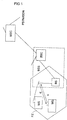
- FIG 1 is a cellular mobile network, such as the GSM (Global System for Mobile Communication) system represented by a variety of mobile exchanges MSC exists, which are networked together, respectively establish access to a PSTN / ISDN landline. Further these mobile exchanges are MSC with at least each connected to a base station controller BSC, which also by a data processing system may be formed.
- GSM Global System for Mobile Communication
- BSC base station controller
- a similar Architecture is also found in a UMTS (Universal Mobile Telecommunication System).
- Each base station controller BSC is in turn with at least a base station BS connected.
- a base station BS is a radio station that has a radio interface Radio connection to other radio stations, so-called mobile stations MS can build. Between the mobile stations MS and the base station BS assigned to these mobile stations MS can use radio signals information within radio channels f lying within frequency bands b, transmitted become.
- the range of the radio signals of a base station essentially define a radio cell FZ.
- Base stations BS and a base station controller BSC be combined into a base station system BSS.
- the Base station system BSS is also used for radio channel management or allocation, the data rate adjustment, the monitoring the radio transmission link, hand-over procedures, and in the case of a CDMA system for the allocation of those to be used Spreading code sets, responsible and transmits the necessary Signaling information to the mobile stations MS.
- FDD Frequency Division Duplex
- GSM Global System for Mobile communications
- uplink u Mobile station (transmitting unit) to base station (receiving unit)
- Downlink d base station (transmission unit) to the mobile station (Receiving unit)
- FDMA Frequency Division Multiple Access
- transmission unit also communication unit, transmitting unit, Receiving unit, communication terminal, radio station, mobile station or base station.
- transmission unit also communication unit, transmitting unit, Receiving unit, communication terminal, radio station, mobile station or base station.
- Receiving unit communication terminal, radio station, mobile station or base station.
- Terms and examples often refer to one GSM mobile radio system; they are by no means limited to but by the description of one Skilled also easy on others, possibly future, Mobile radio systems, such as CDMA systems, in particular wide-band CDMA systems be imaged.
- data can be transferred via a Radio interface efficiently transmitted, separated and one or more specific compounds or the corresponding one Be assigned to participants.
- This can be a time division multiple access TDMA, a frequency division multiple access FDMA, a code division multiple access CDMA or a combination of several of these
- the frequency band b is split into a plurality of frequency channels f disassembled; these frequency channels are accessed by time division multiple access TDMA divided into time slots ts.
- TDMA time division multiple access
- the within one Time slot ts and a frequency channel f transmit Signals can be modulated by connection individual data Spreading codes, so-called CDMA codes cc are separated.
- the resulting physical channels become one defined scheme associated with logical channels.
- logical Channels basically distinguish two types: Signaling channels (or control channels) for the transmission of Signaling information (or control information) and Traffic Channels (Traffic Channel TCH) for transmission of Payload.
- the following is an example of a method for synchronization a mobile station MS with a base station BS explains: During a first step of the initial base station search or cell search (initial cell search procedure) the mobile station uses the primary synchronization channel (primary synchronization channel SCH (PSC)) to a Timeslot synchronization with the strongest base station too to reach. This can be done by a matched filter (matched filter) or a corresponding circuit can be ensured the primary synchronization code cp, that of all Base stations is sent out, is adjusted. It will from all base stations BS the same primary synchronization code cp of length 256 sent out.
- PSC primary synchronization channel
- the mobile station determines by correlation from a receive sequence the received signal sequences K (i) according to a principle that in Figures 6 to 11 and related description is explained. It will be at the output of a matched filter (matched filter) for each received signal sequence each located within the reception range of the mobile station Base station peaks output. The detection of the position the strongest peak allows the determination of the timing the strongest base station modulo the slot length. Around To ensure greater reliability, the output can the matched filter over the number of time slots accumulated non-coherently. So the mobile station is running a correlation over a signal sequence of length 256 chips as a matched-filter operation.
- the synchronization code cp is corresponding to a signal sequence K (i) according to a principle as in FIG. 5 and associated ones Description explained, formed or may be formed be or is available in such a way.
- the signal sequence K (i) or the synchronization code cp of length 256 is off two signal sub-sequences K1 (j), K2 (k), each of length 16 comprise, formed or may be formed. These Signal subsequences form a signal subsequence pair (K1 (j) K2 (k)).
- a signal sequence K (i) which can be obtained in this way can also be used “hierarchical signal sequence” or “hierarchical correlation sequence” to be named.
- a signal subsequence can also be “short Correlation sequence "or” constituent sequence ".
- W n can therefore assume the values + 1, -1, + i or -i or, in particular, assume the values +1 or -1 for the generation of binary Golay sequences.
- W n is also referred to as a unit size.
- the set of quantities D n used for a Golay sequence, which can be calculated from the permutation P n is also called a delay matrix; the set of chosen weights W n is also called a weight matrix.
- This sequence can be used as one of the signal subsequences, such as K1 (j).
- the autocorrelation function of one by two signal subsequences formed signal sequence K (i) has in contrast to a in conventional methods used orthogonal gold code in the general worse autocorrelation properties. she has, for example, higher secondary maxima and a higher effective value the minor minima.
- UMTS link-level simulations show that when using such signal sequences K (i) in the PSC for slot synchronization at a frequency offset (Frequency error) between transmitter and receiver of Synchronization error as opposed to using an orthogonal Gold codes is generally higher.
- K (i) or synchronization codes cp becomes the calculation effort for the calculation of the correlation sums, ie for the determination the signal sequence K (i) in the receiving mobile station MS for the purpose of synchronization, significantly reduced without one simultaneous increase of the synchronization error in purchase to have to take. Also, the use of expensive quartz be dispensed with in the receiver for frequency stabilization.
- the UMTS system can signal subsequence pairs be determined, which is at frequency error 0 kHz and 5 kHz and 10 kHz in terms of synchronization error, surprisingly behave just as well as a conventional one orthogonal gold code that is not hierarchical, and known for the synchronization very good properties having.
- At least one Signal subsequence one with respect to the secondary maxima of the autocorrelation function also optimized for frequency errors Golay sequence, especially the length 16.
- the permutation P), P 2 , P 3 , P 4 and binary unit size W 1 , W used to form the signal subsequence 2 , W 3 , W 4 is taken from the following set of permutation unit size pairs (P 1 P 2 P 3 P 4 , W 1 W 2 W 3 W 4 ;): 3201, + 1-1 + 1 + 1; 3201, -1-1 + 1 + 1; 3201, + 1-1-1 + 1; 3201, + 1-1 + 1-1; 3201; -1-1 + 1-1; 3201; -1-1 + 1-1; 3201, + 1-1-1-1; 3201, + 1-1-1-1; 3201, -1-1-1-1; 1023, + 1 + 1-1 + 1; 1023, -1 + 1-1 + 1; 1023, + 1-1-1 + 1; 1023, -1-1-1 + 1; 1023, + 1 + 1-1-1; 1023, + 1 + 1-1-1; 1023, + 1 + 1-1-1; 1023, + 1 + 1-1-1; 1023,
- the permutations P 1 , P 2 , P 3 , P 4 and binary unit size W 1 used to form the signal subsequence, W 2 , W 3 , W 4 is taken from the following set of permutation unit size pairs (P 1 P 2 P 3 P 4 , W 1 W 2 W 3 W 4 ;): 3201, + 1-1 + 1 + 1; 3201, -1-1-1 + 1; 3201, -1-1 + 1-1; 3201, + 1-1-1-1, and the permutation (P 1 P 2 P 3 P 4 ) used to form the second signal subsequence is 3201.
- the Golay Tech also by specifying the delay matrix and the weight matrix.
- FIG. 2 shows a radio station which is a mobile station MS can, consisting of a control unit or interface unit MMI, a control device STE, a processing device VE, a power supply SVE, a receiving device EE and possibly a transmitting device SE.
- the control device STE consists essentially of a programmatic microcontroller MC, writing and reading can access memory modules SPE.
- the microcontroller MC controls and controls all essential elements and functions of the radio station.
- the processing device VE can also by a digital Signal processor DSP be formed, also on Memory blocks SPE can access. By the processing device VE can also add and multiply be realized.
- SPE is the program data used to control the radio station and the communication process, in particular the signaling procedures, be needed and during processing Information generated by signals stored. Furthermore can be signal sequences K (i), which for correlation purposes and intermediate results of correlation sum calculations get saved.
- the under the Invention lying signal sequences K (i) can thus in the mobile station and / or the base station to be stored. It It is also possible that one or more of the above listed Permutation unit size pairs or signal subsequences derived therefrom or signal subsequence pairs (K1 (j); K2 (k)) in the Mobile station and / or the base station are stored.
- a signal sequence K (i) from a signal subsequence pair (K1 (j); K2 (k)) and / or a signal subsequence of a permutation unit size pair is formed.
- a signal sequence K (i) stored be in fixed or variable intervals for synchronization purposes is sent out.
- the storage of the signal sequences or the signal subsequences can also by storing appropriate information in any coded form and by means of Storage, such as volatile and / or non-volatile Memory modules or by appropriately configured Adder or multiplier inputs or equivalent realized similar hardware designs be.
- the high-frequency part HF may consist of the transmitting device SE, with a modulator and an amplifier V and a receiving device EE with a demodulator and also one Amplifier.
- analog / digital conversion the analog Audio signals and the analogue of the receiving device EE originating signals converted into digital signals and from the digital Signal processor DSP processed. After processing If necessary, the digital signals are converted by digital / analogue conversion in analog audio signals or other output signals and analog signals to be supplied to the transmitter SE are converted. For this purpose, if necessary, a modulation or demodulation carried out.
- the transmitting device SE and the receiving device EE is via the synthesizer SYN the frequency of a voltage controlled Oszilators VCO supplied.
- the voltage-controlled Oscillator VCO can also be the system clock for clocking Processor facilities of the radio station are generated.
- a mobile radio system is an antenna device ANT provided.
- GSM Global System for Mobile Communication
- GSM Global System for Mobile Communication
- the radio station can also be a base station BS act.
- the speaker element and the Microphone element of the control unit MMI through a connection to a mobile network, for example via a base station controller BSC or a switching device MSC replaced.
- the base station BS has a corresponding Variety of transmitting or receiving devices.
- FIG. 3 shows a received signal sequence E (1) in which it is located also by a signal sequence derived from a received signal can act, the length w is shown.
- pairwise multiplication of the elements of the signal sequence with corresponding elements of the received signal sequence and the subsequent summation can also be described in vector notation as the formation of a scalar product, as long as the elements of the signal sequence and the elements of the received signal sequence are combined to form a vector of a Cartesian coordinate system:
- the maximum are sought, the maximum of the correlation sums S with a predetermined threshold value are compared, and thus determined be whether in the received signal E (1) the predetermined Signal sequence K (i) is included and if so, where in the received signal E (1) it is, and so two radio stations together be synchronized or data to which an individual Spreading code modulated in the form of a signal sequence K (i) was detected.
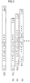
- FIG. 5 shows the formation of a signal sequence K (i) which is based on two signal subsequences K2 (k) of length n2 and K1 (j) of length n1.
- the signal subsequence K2 (k) is repeated n1 times, and thereby modulated by the signal subsequence K1 (j).
- sequence f2 that out the repeated, sequentially mapped signal subsequences K2 (k), and a sequence f1, which is stretched by a Signal subsequence K1 (j) over the sequence f2 is mapped.
- Sequence f1 By multiplying the elements of the sequence f2 with the corresponding elements of the sequence f2 illustrated Sequence f1 produces the new signal sequence K (i) of length n.
- This Generation of a signal sequence K (i) is still in the picture below once with an example of two binary signal subsequences the length 4 shown.
- the invention is not limited to signal subsequences of Length 4 or signal sequences of length 16 limited. Also is the invention is not limited to the mathematical description used above limited.
- the content is the following representation for Signal subsequences of length 16 or signal sequences of length 256 the mathematical representation used above and is therefore also included in the invention:
- K2 ⁇ a, a, a, -a, -a, a, -a, -a, a, a, a, -a, a, -a, a, -a, a, -a, a, -a, a, a, -a, a, a, -a, a, a, a, -a, a, a, a>
- Signal sequences K (i) formed in this way can be simplified Calculation of correlation sums of these signal sequences K (i) be used with received signal sequences E (1).
- the thus formed Signal sequence of length 256 for example, for synchronization purposes as primary synchronization code cp the Length 256 will be sent out.
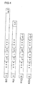
- FIGS. 6 to 8 A schematic representation of such a simplified and thus also faster and more cost-effective calculation of correlation sums S is shown in FIGS. 6 to 8, which will be discussed below.
- a partial correlation sum TS (z) is formed.
- the correlation sum of the second signal sub-sequence K2 (k) is formed with the corresponding section of the received signal sequence E (1).
- the second signal subsequence K2 ⁇ k ⁇ is displaced by one element as illustrated and the correlation sum is also formed with the corresponding element of the received signal sequence E (1) etc.
- the nth element of the partial correlation sum sequence TS (n1 * n2-1) is correspondingly calculated after n-1 shifts of the second signal subsequence K2 (k) in relation to the received signal sequence E (1).
- the resulting partial correlation sum sequence TS (z) is in Upper area of Figure 7 shown. From this sub-correlation sum sequence Now every n2th element is selected and with the corresponding element of the first signal subsequence K1 (j) multiplied in pairs.
- the first correlation sum S0 is generated by the scalar product of these two vectors.
- FIG. 7 shows in the lower area the corresponding calculation of further correlation sums S1 and S2 by the selection n2-ter by 1 or 2 to the right of the elements which are the first elements selected:
- either the complete first Partial correlation sum sequence TS (z) over the entire received signal sequence E (1) are calculated and then the individual Correlation sums or only when needed to calculate a new correlation sum the corresponding additionally required Partial correlation totals are calculated.
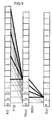
- FIG. 8 again shows the two-step method for calculating correlation sums S, this time using of the example of two binary shown in FIG Signal sequences of length 4.
- a first step the partial correlation sums TS (z) of the second signal subsequence K2 (k) + - ++ with corresponding ones Sections of the received signal sequence E (1) calculated, and then in a second step every fourth element of the so generated Partial correlation sum sequence TS (z) selected with the corresponding element of the first signal subsequence K1 (j) +++ multiplied and summed up to the correlation sequence S0.
- the thick drawn lines represent the new to be performed Calculation steps for the calculation of a further correlation sum S1, in the event that the remaining Partial correlation sums TS already calculated and stored were.
- This embodiment variant can be as efficient as possible in terms of memory be performed when first every n2-th partial correlation sum is calculated. For this, the samples are buffered.
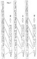
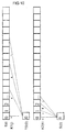
- Figures 9 to 10 represent another embodiment for the simplified calculation of correlation sums S by the already mentioned example of two binary signal subsequences of length 4 ago.
- FIG. 10 again shows the calculation of a first correlation sum S0 at the first every 4th element of the received signal sequence E (1) is selected, these elements with appropriate Elements of the first signal subsequence K1 (j) +++ - multiplied and by summing up the partial results the Partial correlation sum TS (0) is calculated.
- a second Step will be the first four consecutive elements the partial correlation sum sequence TS (z) with the corresponding ones Elements of the second signal subsequence K2 (k) + - ++ multiplied and the resulting partial results for the correlation sum S0 added up.
- Another embodiment of the invention makes from the regular design principle of the signal sequence K (i) conditional regular (almost periodic) structure of the aperiodic Autocorrelation function of this signal sequence use.
- To accelerated search for the Signal sequence in the received signal sequence you can check the regularity take advantage of the position of the maxima. Once a secondary maxima was found, one can, due to the periodicity, the location predict the other maxima, i. you calculate the correlation sum only in these places. In this way you can quickly detect the main maximum. Indeed It may be at the supposed secondary maximum only to a random (due to the amount of noise) increased value act. In this case one becomes at the potential places of the expected main maximums actually find no maximum. Therefore In this case, the hypothesis is rejected and the calculation conventionally continued.
- embodiments of the invention are for calculation scalar products, correlation sums and / or subcorrelation sums Efficient Golay correlators used.
- Figure 11 shows an efficient hierarchical correlator for signal sequences, with Golay sequences as constituent sequences K1, K2 X, Y of length nx or ny are used.
- the correlator consists of two consecutive Matched Filters (Figure 11 a), each as Efficient Golay correlators are formed.
- Figure 11 b) shows the matched Filter for the sequence X and
- Figure 11 c) shows the matched filter for the episode Y.
- the correlation of a Golay sequence of length 2 N can now be carried out efficiently as follows:
- n runs from 1 to N:
- R a (N) (k) W * n * R b (N-1) (k) + R a (N-1) (k D n )
- R b (N) (k) W * n * R b (N-1) (k) - R a (N-1) (k D n ) wherein W * n the complex conjugate designated by W n. If the weights W are real, W * n is identical to W n .
- R a (N) (k) is then the correlation sum to be calculated.
- x 8-1 15 complex adders.
- the present invention is not based on radio transmission systems but can also be used when using other transmission methods e.g. acoustic method (ultrasound), in particular for the purposes of sonography, or optical Method, for example, the infrared measurement according Lidar principles be used.
- acoustic method ultrasound
- optical Method for example, the infrared measurement according Lidar principles be used.
- Another application is the study of changes in the spectral composition of backscattered signals.
Claims (14)
- Procédé de synchronisation entre une station de base (BS) et une station mobile (MS),dans lequel une suite de signaux K(i) de longueur 256 est émise par la station de base (BS), laquelle peut être obtenue du fait qu'une deuxième suite partielle de signaux K2(k) de longueur n2 = 16 est répétée n1 = 16 fois tout en subissant une modulation avec la première suite partielle de signaux K1(j) de longueur n1 = 16, avec:au moins l'une des suites partielles de signaux étant une séquence de Golay Xn(k) de longueur nx=n1=16, laquelle est constituable par la relation suivante:
n = 1, 2, ..., NX
Dn = 2 P n
avec
nx = 16 = 2NX
NX=4
δ (k): fonction delta de Kronecker,la permutation P1, P2, P3, P4, utilisée pour constituer une suite partielle de signaux, et la grandeur unitaire W1, W2, W3, W4 étant tirées de l'ensemble suivant de paires de permutation et de grandeurs unitaires (P1 P2 P3 P4, W1 W2 W3 W4;):
3201, +1-1+1+1; 3201, -1-1+1+1; 3201, +1-1-1+1; 3201, -1-1-1+1; 3201, +1-1+1-1; 3201, -1-1+1-1; 3201, +1-1-1-1; 3201, -1-1-1-1; 1023, +1+1-1+1; 1023, -1+1-1+1; 1023, +1-1-1+1; 1023, -1-1-1+1; 1023, +1+1-1-1; 1023, -1+1-1-1; 1023, +1-1-1-1; 1023, -1-1-1-1 etdans lequel la suite de signaux K(i) est reçue par une station mobile et subit un traitement à des fins de synchronisation. - Procédé selon la revendication 1,
dans lequel la suite de signaux K(i) peut être obtenue selon la loi de formation suivante par répétition modulée d'une suite partielle de signaux a composée de 16 éléments:
K = <a, a, a, -a, -a, a, -a, -a, a, a, a, -a, a, -a, a, a>. - Procédé selon la revendication 1,
la suite partielle de signaux K1(j) étant une séquence de Golay qui est définie par la matrice de retard D = [8, 4, 1, 2] et la matrice de poids W = [1, -1, 1, 1]. - Procédé selon la revendication 1,
la permutation P1, P2, P3, P4, utilisée pour constituer la première suite partielle de signaux, et la grandeur unitaire W1, W2, W3, W4 étant tirées de l'ensemble suivant de paires de permutation et de grandeurs unitaires (P1 P2 P3 P4, W1 W2 W3 W4;): 3201, +1-1+1+1; 3201, -1-1-1+1; 3201, -1-1+1-1; 3201, +1-1-1-1; et la permutation (P1, P2, P3, P4) utilisée pour constituer la deuxième suite partielle de signaux étant égale à 3201. - Procédé selon l'une des revendications précédentes,
dans lequel la suite de signaux K(i) est reçue en tant que partie d'une suite de signaux de réception E(1) par la station mobile (MS) et subit un traitement subséquent à des fins de synchronisation. - Procédé selon l'une des revendications précédentes,
dans lequel la suite de signaux K(i) est déterminée par la station mobile (MS), tout en étant qu'il est fait appel, dans la station mobile, à des connaissances sur les première et deuxième suites partielles de signaux K1(j) K2(k). - Procédé selon l'une des revendications précédentes,dans lequel des sommes de corrélation S de la suite de signaux K(i) sont déterminées dans la station mobile (MS) avec des parties correspondantes de la suite de signaux de réception E(1),une suite de sommes de corrélation partielle TS(z) de la suite partielle de signaux K2(k) étant calculée avec des parties correspondantes de la suite de signaux de réception E(1) et n1 éléments de la suite des sommes de corrélation partielle TS(z) étant sélectionnés pour le calcul d'une somme de corrélation S et étant multipliés par la suite partielle de signaux K1(j) au sens d'un produit scalaire.
- Procédé selon la revendication 7, dans lequel, pour le calcul d'une somme de corrélation S, n1 respectivement n2ièmes éléments de la suite de sommes de corrélation partielle TS(z) sont sélectionnés.
- Procédé selon l'une des revendications 1 à 6,dans lequel des sommes de corrélation S de la suite de signaux K(i) sont déterminées dans la station mobile (MS) avec des parties correspondantes de la suite de signaux de réception E(1),une suite de sommes de corrélation partielle TS(z) de la suite partielle de signaux K1(j) étant calculée avec des éléments sélectionnés de la suite de signaux de réception E(1) et n2 éléments de la suite des sommes de corrélation partielle TS(z) étant multipliés, pour le calcul d'une somme de corrélation S, par la suite partielle de signaux K2(k) au sens d'un produit scalaire.
- Procédé selon la revendication 9, dans lequel,
pour le calcul d'une somme de corrélation partielle TS, n1 respectivement n2ièmes éléments de la suite de signaux de réception E(1) sont sélectionnés. - Procédé selon l'une des revendications 7 à 11, dans lequel
des sommes de corrélation partielle calculées TS sont mises en mémoire et sont utilisées pour le calcul d'une autre somme de corrélation S. - Procédé selon l'une des revendications précédentes, dans lequel
on utilise, dans la station mobile (MS), un efficient Golay correlator (EGC) au moins en partie pour la détermination de la suite de signaux, en particulier pour le calcul d'au moins une somme de corrélation. - Station de base (BS)comprenant des moyens (SPE) de mise en mémoire resp. de constitution d'une suite de signaux K(i), laquelle peut être obtenue du fait qu'une deuxième suite partielle de signaux K2(k) de longueur n2 = 16 est répétée n1 = 16 fois tout en subissant une modulation avec la première suite partielle de signaux K1(j) de longueur n1 = 16, avec:au moins l'une des suites partielles de signaux étant une séquence de Golay Xn(k) de longueur nx=n1=16, laquelle est constituable par la relation suivante:
n = 1, 2, -, NX
Dn = 2 Pn
avec
nx = 16 = 2NX
NX=4
δ (k): fonction delta de Kronecker,la permutation P1, P2, P3, P4, utilisée pour constituer une suite partielle de signaux, et la grandeur unitaire W1, W2, W3, W4 étant tirées de l'ensemble suivant de paires de permutation et de grandeurs unitaires (P1 P2 P3 P4, W1 W2 W3 W4;):
3201, +1-1+1+1; 3201, -1-1+1+1; 3201, +1-1-1+1; 3201, -1-1-1+1; 3201, +1-1+1-1; 3201, -1-1+1-1; 3201, +1-1-1-1; 3201, -1-1-1-1; 1023, +1+1-1+1; 1023, -1+1-1+1; 1023, +1-1-1+1; 1023, -1-1-1+1; 1023, +1+1-1-1; 1023, -1+1-1-1; 1023, +1-1-1-1; 1023, -1-1-1-1 etavec des moyens pour émettre cette suite de signaux K(i) aux fins de la synchronisation sur une unité réceptrice (MS). - Station mobile (MS)aménagée de manière telle que, aux fins de la synchronisation entre une station de base (BS) et la station mobile (MS), elle détermine une suite de synchronisation K(i), laquelle peut être obtenue du fait qu'une deuxième suite partielle de signaux K2(k) de longueur n2 = 16 est répétée n1 = 16 fois tout en subissant une modulation avec la première suite partielle de signaux K1(j) de longueur n1 = 16, avec:au moins l'une des suites partielles de signaux étant une séquence de Golay Xn(k) de longueur nx=n1=16, laquelle est constituable par la relation suivante:
n = 1, 2, ..., NX
Dn = 2 P n
avec
nx = 16 = 2NX
NX=4
δ (k): fonction delta de Kronecker,la permutation P1, P2, P3, P4, utilisée pour constituer une suite partielle de signaux, et la grandeur unitaire W1, W2, W3, W4 étant tirées de l'ensemble suivant de paires de permutation et de grandeurs unitaires (P1 P2 P3 P4, W1 W2 W3 W4;):
3201, +1-1+1+1; 3201, -1-1+1+1; 3201, +1-1-1+1; 3201, -1-1-1+1; 3201, +1-1+1-1; 3201, -1-1+1-1; 3201, +1-1-1-1; 3201, -1-1-1-1; 1023, +1+1-1+1; 1023, -1+1-1+1; 1023, +1 -1-1+1; 1023, -1-1-1+1; 1023, +1+1-1-1; 1023, -1+1-1-1; 1023, +1-1-1-1; 1023, -1-1-1-1;.
Priority Applications (1)
| Application Number | Priority Date | Filing Date | Title |
|---|---|---|---|
| EP00916836A EP1173944B1 (fr) | 1999-04-29 | 2000-02-15 | Procede pour la formation et la determination d'une sequence de signaux, procede de synchronisation, unite emettrice et unite receptrice |
Applications Claiming Priority (6)
| Application Number | Priority Date | Filing Date | Title |
|---|---|---|---|
| DE19919545 | 1999-04-29 | ||
| DE19919545A DE19919545B4 (de) | 1999-04-29 | 1999-04-29 | Verfahren zur Bildung einer Signalfolge |
| EP99109791 | 1999-05-18 | ||
| EP99109791 | 1999-05-18 | ||
| PCT/EP2000/001231 WO2000067404A1 (fr) | 1999-04-29 | 2000-02-15 | Procede pour la formation et la determination d'une sequence de signaux, procede de synchronisation, unite emettrice et unite receptrice |
| EP00916836A EP1173944B1 (fr) | 1999-04-29 | 2000-02-15 | Procede pour la formation et la determination d'une sequence de signaux, procede de synchronisation, unite emettrice et unite receptrice |
Publications (2)
| Publication Number | Publication Date |
|---|---|
| EP1173944A1 EP1173944A1 (fr) | 2002-01-23 |
| EP1173944B1 true EP1173944B1 (fr) | 2005-02-09 |
Family
ID=26053133
Family Applications (2)
| Application Number | Title | Priority Date | Filing Date |
|---|---|---|---|
| EP00916836A Expired - Lifetime EP1173944B1 (fr) | 1999-04-29 | 2000-02-15 | Procede pour la formation et la determination d'une sequence de signaux, procede de synchronisation, unite emettrice et unite receptrice |
| EP00909187A Expired - Lifetime EP1173943B1 (fr) | 1999-04-29 | 2000-02-16 | Procede pour former et pour determiner une sequence de synchronisation, procede de synchronisation, unite d'emission et unite de reception |
Family Applications After (1)
| Application Number | Title | Priority Date | Filing Date |
|---|---|---|---|
| EP00909187A Expired - Lifetime EP1173943B1 (fr) | 1999-04-29 | 2000-02-16 | Procede pour former et pour determiner une sequence de synchronisation, procede de synchronisation, unite d'emission et unite de reception |
Country Status (11)
| Country | Link |
|---|---|
| US (2) | US7062002B1 (fr) |
| EP (2) | EP1173944B1 (fr) |
| JP (2) | JP4342109B2 (fr) |
| KR (2) | KR100669570B1 (fr) |
| CN (2) | CN100521589C (fr) |
| AU (1) | AU777074B2 (fr) |
| BR (1) | BRPI0010601B1 (fr) |
| DE (2) | DE50009481D1 (fr) |
| ES (1) | ES2233356T3 (fr) |
| HU (2) | HUP0200968A2 (fr) |
| WO (2) | WO2000067404A1 (fr) |
Families Citing this family (50)
| Publication number | Priority date | Publication date | Assignee | Title |
|---|---|---|---|---|
| DE19953895A1 (de) * | 1999-11-10 | 2001-05-17 | Bosch Gmbh Robert | Verfahren zur Korrelation von zeitdiskreten Signalabschnitten |
| DE19961557A1 (de) * | 1999-12-20 | 2001-07-05 | Infineon Technologies Ag | Verfahren und Einrichtung zum Synchronisieren eines Mobilfunkempfängers mit einer Zeitschlitzstruktur eines empfangenen Funksignals |
| ES2164613B1 (es) * | 2000-08-16 | 2003-05-16 | Fuente Vicente Diaz | Metodo, transmisor y receptor para comunicacion digital de espectro ensanchado mediante modulacion de secuencias complementarias golay. |
| US20020150149A1 (en) * | 2000-09-29 | 2002-10-17 | Yoshihiro Tanno | Code detection circuit and code detection method |
| GB0024530D0 (en) * | 2000-10-06 | 2000-11-22 | Roke Manor Research | Use of multiple offsets with concatenated periodically extended complementary sequences |
| DE10124223A1 (de) * | 2001-05-18 | 2002-11-21 | Philips Corp Intellectual Pty | Verfahren und Einrichtung zur Synchronisation eines Funksenders mit einem Funkempfänger |
| DE10125013A1 (de) * | 2001-05-22 | 2002-11-28 | Siemens Ag | Verfahren zur Synchronisation von Basisstationen in einem Funk-Kommunikationssystem |
| US7092469B1 (en) | 2001-09-26 | 2006-08-15 | Nokia Corporation | Synchronization signal detector and method of detection of synchronization signal |
| KR100461545B1 (ko) * | 2001-10-20 | 2004-12-16 | 한국전자통신연구원 | 동기 채널의 동기코드 생성 및 검출 방법 |
| TW200727605A (en) * | 2002-09-12 | 2007-07-16 | Interdigital Tech Corp | Mitigation of interference in cell search by wireless transmit and receive units |
| KR100905572B1 (ko) * | 2002-12-03 | 2009-07-02 | 삼성전자주식회사 | 직교 주파수 분할 다중 방식을 사용하는 통신시스템에서 프리앰블 시퀀스 생성 장치 및 방법 |
| CN1283059C (zh) * | 2003-01-23 | 2006-11-01 | 上海贝尔阿尔卡特股份有限公司 | 一种载频同步的方法和装置 |
| EP1443669B1 (fr) | 2003-01-31 | 2017-05-03 | France Brevets | Dispositif pour synchronisation et identification de code |
| KR100770912B1 (ko) * | 2003-06-16 | 2007-10-26 | 삼성전자주식회사 | 직교 주파수 분할 다중 방식을 사용하는 통신 시스템에서프리앰블 시퀀스 생성 장치 및 방법 |
| WO2005074166A1 (fr) | 2004-01-29 | 2005-08-11 | Neocific, Inc. | Procedes et appareil de superpositon de signaux multi-porteuses et a spectre etale a sequence directe dans un systeme de transmission sans fil a bande large |
| CN101854188B (zh) | 2004-01-29 | 2013-03-13 | 桥扬科技有限公司 | 用于多载波、多小区无线通信网络的方法和装置 |
| WO2005109705A1 (fr) | 2004-05-01 | 2005-11-17 | Neocific, Inc. | Procedes et appareil destines a la communication avec duplexage a repartition dans le temps |
| CN1943152B (zh) | 2004-02-13 | 2011-07-27 | 桥扬科技有限公司 | 用于具有自适应发射和反馈的多载波通信系统的方法和设备 |
| US7532661B2 (en) * | 2004-04-19 | 2009-05-12 | Texas Instruments Incorporated | Additional hierarchical preamble for support of FDMA channel in a multi-band OFDM system |
| CN101356517B (zh) * | 2005-09-21 | 2010-06-23 | Nxp股份有限公司 | 总线电路 |
| US8429502B2 (en) * | 2005-11-16 | 2013-04-23 | Qualcomm Incorporated | Frame format for millimeter-wave systems |
| US8583995B2 (en) * | 2005-11-16 | 2013-11-12 | Qualcomm Incorporated | Multi-mode processor |
| US8910027B2 (en) * | 2005-11-16 | 2014-12-09 | Qualcomm Incorporated | Golay-code generation |
| WO2007066292A2 (fr) * | 2005-12-08 | 2007-06-14 | Koninklijke Philips Electronics N.V. | Systeme, appareil et procede pour un schema de synchronisation robuste destine aux sytemes de communication numerique |
| KR100656826B1 (ko) * | 2005-12-23 | 2006-12-13 | 주식회사 케이티 | 준동기 부호분할 다원접속 시스템의 낮은 상관구역 수열군생성 장치 및 방법 |
| JP5023539B2 (ja) * | 2006-04-11 | 2012-09-12 | 富士通セミコンダクター株式会社 | 半導体装置及び信号処理方法 |
| CN101192881A (zh) * | 2006-11-30 | 2008-06-04 | 昂达博思公司 | 用于快速上行链路空中接口同步的系统和方法 |
| CN101197590B (zh) * | 2006-12-04 | 2011-08-17 | 海能达通信股份有限公司 | 一种在无线通信中实现位同步数字化的方法及其系统 |
| JP5031037B2 (ja) * | 2006-12-19 | 2012-09-19 | エルジー エレクトロニクス インコーポレイティド | 効率的な検出のためのシーケンス生成方法及びこれを用いた信号送受信方法 |
| GB2458418B (en) | 2006-12-19 | 2011-08-03 | Lg Electronics Inc | Sequence generating method for efficient detection and method for transmitting and receiving signals using the same |
| US8363692B2 (en) * | 2007-02-05 | 2013-01-29 | Lg Electronics Inc. | Method for generating 2 or more sequence set, and method for generating sequence for the same |
| KR101414610B1 (ko) * | 2007-02-05 | 2014-07-04 | 엘지전자 주식회사 | 2개 이상의 시퀀스 세트 생성 방법 및 이를 위한 시퀀스생성 방법 |
| KR100922970B1 (ko) * | 2007-02-08 | 2009-10-22 | 삼성전자주식회사 | 통신 시스템에서의 훈련 시퀀스 코드의 생성/변조 방법 및 이를 이용한 데이터 송신 장치 |
| KR101467751B1 (ko) * | 2007-04-24 | 2014-12-03 | 엘지전자 주식회사 | 이동 통신 시스템에서 시퀀스 생성 방법 및 시퀀스 기반의신호 송신 방법 |
| WO2008130206A1 (fr) * | 2007-04-24 | 2008-10-30 | Lg Electronics Inc. | Procédé pour générer une séquence et de procédé pour émettre un signal sur la base de la séquence dans un système de communication |
| JP5113242B2 (ja) * | 2007-05-17 | 2013-01-09 | エルジー エレクトロニクス インコーポレイティド | 無線通信システムにおいて同期信号を伝送する方法 |
| DE102007028732A1 (de) * | 2007-06-21 | 2008-12-24 | Continental Automotive Gmbh | Mehrfache Spreizung/Entspreizung von Spreizspektrumsignalen durch mehrfache Spreizfolgen |
| KR100938756B1 (ko) | 2007-07-06 | 2010-01-26 | 엘지전자 주식회사 | 무선통신 시스템에서 셀 탐색 과정을 수행하는 방법 |
| US8472497B2 (en) * | 2007-10-10 | 2013-06-25 | Qualcomm Incorporated | Millimeter wave beaconing with directional antennas |
| US8856628B2 (en) * | 2007-10-10 | 2014-10-07 | Qualcomm Incorporated | Method and apparatus for generation and usage of extended golay codes |
| RU2479123C2 (ru) * | 2007-12-21 | 2013-04-10 | Телефонактиеболагет Лм Эрикссон (Пабл) | Mbsfn dob-поиск сот и генерирование кодов синхронизации |
| KR100911307B1 (ko) | 2008-03-17 | 2009-08-11 | 엘지전자 주식회사 | 기준신호 전송 방법 |
| WO2009116769A1 (fr) | 2008-03-17 | 2009-09-24 | Lg Electronics Inc. | Procédé de transmission de signal de référence et émetteur l'utilisant |
| US8107443B2 (en) * | 2009-02-10 | 2012-01-31 | Mediatek Inc. | Method of performing cell search for a wireless communications system |
| US8908792B2 (en) * | 2009-06-23 | 2014-12-09 | Intel Corporation | Apparatus and methods using an efficient Golay correlator running at 1.5 the sampling rate in wireless communication systems |
| US10257325B2 (en) | 2015-02-05 | 2019-04-09 | Samsung Electronics Co., Ltd. | System, apparatus, and method for configuring preamble and synchronizing frame |
| AU2015385427B2 (en) | 2015-03-06 | 2018-06-14 | Telefonaktiebolaget Lm Ericsson (Publ) | Beam forming using an antenna arrangement |
| KR20170020001A (ko) * | 2015-08-13 | 2017-02-22 | 삼성전자주식회사 | 통신 시스템에서 신호 송수신 장치 및 방법 |
| WO2017190777A1 (fr) * | 2016-05-04 | 2017-11-09 | Telefonaktiebolaget Lm Ericsson (Publ) | Formation de faisceau au moyen d'un agencement d'antennes |
| US10708751B2 (en) * | 2016-08-11 | 2020-07-07 | Qualcomm Incorporated | Detection of technologies for coexistence |
Family Cites Families (15)
| Publication number | Priority date | Publication date | Assignee | Title |
|---|---|---|---|---|
| EP0663121A4 (fr) | 1992-10-01 | 1997-07-23 | Motorola Inc | Recepteur d'appel selectif pouvant demander une information a un systeme de communications et procede. |
| JPH07297805A (ja) * | 1994-04-28 | 1995-11-10 | Toshiba Corp | スペクトラム拡散符号の同期回路および同期方法 |
| US5717713A (en) * | 1994-11-18 | 1998-02-10 | Stanford Telecommunications, Inc. | Technique to permit rapid acquisition and alert channel signalling for base station-to-user link of an orthogonal CDMA (OCDMA) communication system |
| WO1996039749A1 (fr) * | 1995-06-05 | 1996-12-12 | Omnipoint Corporation | Commande de reglage de synchronisation servant a realiser des telecommunications en duplex a repartition dans le temps |
| US5764630A (en) * | 1996-03-25 | 1998-06-09 | Stanford Telecommunications, Inc. | Forward link carrier recovery in an OCDMA spread spectrum communication system without a pilot tone |
| US5751774A (en) * | 1996-04-04 | 1998-05-12 | Lucent Technologies Inc. | Transmission system for digital audio broadcasting |
| US5748686A (en) * | 1996-04-04 | 1998-05-05 | Globespan Technologies, Inc. | System and method producing improved frame synchronization in a digital communication system |
| US5805646A (en) * | 1996-10-08 | 1998-09-08 | Ericsson Inc. | Synchronization method, and associated circuitry, for improved synchronization of a receiver with a transmitter using early-late testing during coarse synchronization |
| US6181729B1 (en) * | 1997-12-19 | 2001-01-30 | Supergold Communication Limited | Spread spectrum communication |
| US6256304B1 (en) * | 1998-03-31 | 2001-07-03 | Nokia Mobile Phones, Limited | Mobile station using synchronization word order information for improved channel acquisition |
| WO2000014915A2 (fr) * | 1998-09-08 | 2000-03-16 | Siemens Aktiengesellschaft | Procede de formation ou de determination d'une sequence de signaux, unite d'emission et unite de reception |
| JP3411836B2 (ja) * | 1998-10-30 | 2003-06-03 | 松下電器産業株式会社 | 同期捕捉装置及び同期捕捉方法 |
| US6873647B1 (en) * | 1999-02-26 | 2005-03-29 | Qualcomm Incorporated | Method and system for reducing synchronization time in a CDMA wireless communication system |
| US6567482B1 (en) * | 1999-03-05 | 2003-05-20 | Telefonaktiebolaget Lm Ericsson (Publ) | Method and apparatus for efficient synchronization in spread spectrum communications |
| CA2276971A1 (fr) * | 1999-07-06 | 2001-01-06 | Wen Tong | Synchroniseur initial faisant appel au code de golay pour un canal d'acces dans des systemes de communications cellulaires |
-
2000
- 2000-02-15 ES ES00916836T patent/ES2233356T3/es not_active Expired - Lifetime
- 2000-02-15 EP EP00916836A patent/EP1173944B1/fr not_active Expired - Lifetime
- 2000-02-15 DE DE50009481T patent/DE50009481D1/de not_active Expired - Lifetime
- 2000-02-15 JP JP2000616148A patent/JP4342109B2/ja not_active Expired - Lifetime
- 2000-02-15 KR KR1020017013856A patent/KR100669570B1/ko active IP Right Grant
- 2000-02-15 HU HU0200968A patent/HUP0200968A2/hu unknown
- 2000-02-15 US US10/018,312 patent/US7062002B1/en not_active Expired - Lifetime
- 2000-02-15 BR BRPI0010601A patent/BRPI0010601B1/pt active IP Right Grant
- 2000-02-15 CN CNB008068801A patent/CN100521589C/zh not_active Expired - Lifetime
- 2000-02-15 WO PCT/EP2000/001231 patent/WO2000067404A1/fr active IP Right Grant
- 2000-02-15 AU AU38043/00A patent/AU777074B2/en not_active Expired
- 2000-02-16 HU HU0200967A patent/HUP0200967A2/hu unknown
- 2000-02-16 EP EP00909187A patent/EP1173943B1/fr not_active Expired - Lifetime
- 2000-02-16 US US10/018,436 patent/US7010071B1/en not_active Expired - Lifetime
- 2000-02-16 WO PCT/EP2000/001263 patent/WO2000067405A1/fr active IP Right Grant
- 2000-02-16 KR KR1020017013859A patent/KR100669568B1/ko active IP Right Grant
- 2000-02-16 CN CNB008068895A patent/CN100459468C/zh not_active Expired - Lifetime
- 2000-02-16 DE DE50012606T patent/DE50012606D1/de not_active Expired - Lifetime
- 2000-02-16 JP JP2000616149A patent/JP4650978B2/ja not_active Expired - Lifetime
Also Published As
| Publication number | Publication date |
|---|---|
| JP4342109B2 (ja) | 2009-10-14 |
| KR20020013857A (ko) | 2002-02-21 |
| EP1173944A1 (fr) | 2002-01-23 |
| US7010071B1 (en) | 2006-03-07 |
| KR20020013858A (ko) | 2002-02-21 |
| HUP0200968A2 (en) | 2002-07-29 |
| DE50009481D1 (de) | 2005-03-17 |
| BRPI0010601B1 (pt) | 2016-01-19 |
| EP1173943A1 (fr) | 2002-01-23 |
| JP4650978B2 (ja) | 2011-03-16 |
| BR0010601A (pt) | 2002-02-05 |
| US7062002B1 (en) | 2006-06-13 |
| CN100459468C (zh) | 2009-02-04 |
| AU777074B2 (en) | 2004-09-30 |
| KR100669570B1 (ko) | 2007-01-15 |
| AU3804300A (en) | 2000-11-17 |
| HUP0200967A2 (en) | 2002-07-29 |
| DE50012606D1 (de) | 2006-05-24 |
| KR100669568B1 (ko) | 2007-01-15 |
| CN1349690A (zh) | 2002-05-15 |
| JP2002543741A (ja) | 2002-12-17 |
| JP2002543742A (ja) | 2002-12-17 |
| EP1173943B1 (fr) | 2006-04-19 |
| CN100521589C (zh) | 2009-07-29 |
| WO2000067404A1 (fr) | 2000-11-09 |
| WO2000067405A1 (fr) | 2000-11-09 |
| CN1349691A (zh) | 2002-05-15 |
| ES2233356T3 (es) | 2005-06-16 |
Similar Documents
| Publication | Publication Date | Title |
|---|---|---|
| EP1173944B1 (fr) | Procede pour la formation et la determination d'une sequence de signaux, procede de synchronisation, unite emettrice et unite receptrice | |
| EP1112633B1 (fr) | Procede de formation ou de determination d'une sequence de signaux, unite d'emission et unite de reception | |
| DE60125058T2 (de) | Verfahren zur Synchonisierung von Basisstationen in einem Telekommunikationssystem | |
| DE69936455T2 (de) | Kommunikationsverfahren und -vorrichtungen, die auf orthogonalen hadamard-basierten sequenzen mit ausgewählten korrelationseigenschaften beruhen | |
| EP1006670B1 (fr) | Réseau sans fil | |
| EP1825631B1 (fr) | Dispositif de synchronisation et dispositif pour produire un signal de synchronisation | |
| DE60319433T2 (de) | Verfahren und vorrichtung zur erhaltung der synchronisation für tdd drahtlose kommunikation | |
| DE69635370T2 (de) | Cdma datenübertragungsverfahren, sender und empfänger mit benutzung eines supersymbols zur interferenzeliminierung | |
| EP0938782B1 (fr) | Procede et dispositif de transmission | |
| EP3610595B1 (fr) | Emetteur et recepteur et procedes correspondants | |
| DE3047942A1 (de) | Verfahren zum schalten eines empfaengers und korrelators | |
| DE10001854A1 (de) | Verfahren und Vorrichtung zur Ermittlung der Trägerfrequenz von Basisstationen im mobilen Empfänger eines mit W-CDMA arbeitenden zellularen Mobilfunksystems | |
| EP2689535B1 (fr) | Méthode er décodeur pour désétaler des signaux de données étalés par des séquences de walsh | |
| DE69632915T2 (de) | Verfahren zum steuern eines empfängers, und empfänger | |
| DE19919545B4 (de) | Verfahren zur Bildung einer Signalfolge | |
| EP0878064B1 (fr) | Procede de transmission a modulation de code et systeme de transmission fonctionnant d'apres ce procede | |
| EP1238478B1 (fr) | Procede pour la synchronisation d'un signal de reception amcr | |
| DE60124595T2 (de) | Hochleistungszeitschlitzsyncronisation für die anfangszellensuche eines w-cdma systems mit reduziertem hardware | |
| DE102016202875B4 (de) | Verfahren zum Übertragen von Daten | |
| DE19907083A1 (de) | Verfahren zur Bildung bzw. Ermittlung einer Signalfolge, Verfahren zur Synchronisation, Sendeeinheit und Empfangseinheit | |
| DE60312292T2 (de) | Verfahren und Empfänger zur Burstdetektion | |
| DE602004012483T2 (de) | Verfahren und Gerät zum Erzeugen einer Präambel mittels einer chaotischen Folge | |
| WO2001035543A2 (fr) | Procede de synchronisation d'une transmission de signaux en sens ascendant dans un systeme de radiotelecommunication | |
| DE102005035203B4 (de) | Verfahren zum Schätzen einer Kanalimpulsantwort eines Funkkanals sowie Funkstation | |
| DE3013392A1 (de) | Verfahren zur synchronisation periodischer signale |
Legal Events
| Date | Code | Title | Description |
|---|---|---|---|
| PUAI | Public reference made under article 153(3) epc to a published international application that has entered the european phase |
Free format text: ORIGINAL CODE: 0009012 |
|
| 17P | Request for examination filed |
Effective date: 20010924 |
|
| AK | Designated contracting states |
Kind code of ref document: A1 Designated state(s): AT BE CH CY DE DK ES FI FR GB GR IE IT LI LU MC NL PT SE |
|
| 17Q | First examination report despatched |
Effective date: 20040218 |
|
| RBV | Designated contracting states (corrected) |
Designated state(s): DE ES FR GB IT |
|
| GRAP | Despatch of communication of intention to grant a patent |
Free format text: ORIGINAL CODE: EPIDOSNIGR1 |
|
| GRAS | Grant fee paid |
Free format text: ORIGINAL CODE: EPIDOSNIGR3 |
|
| GRAA | (expected) grant |
Free format text: ORIGINAL CODE: 0009210 |
|
| AK | Designated contracting states |
Kind code of ref document: B1 Designated state(s): DE ES FR GB IT |
|
| REG | Reference to a national code |
Ref country code: GB Ref legal event code: FG4D Free format text: NOT ENGLISH |
|
| REG | Reference to a national code |
Ref country code: IE Ref legal event code: FG4D Free format text: GERMAN |
|
| REF | Corresponds to: |
Ref document number: 50009481 Country of ref document: DE Date of ref document: 20050317 Kind code of ref document: P |
|
| GBT | Gb: translation of ep patent filed (gb section 77(6)(a)/1977) |
Effective date: 20050320 |
|
| REG | Reference to a national code |
Ref country code: ES Ref legal event code: FG2A Ref document number: 2233356 Country of ref document: ES Kind code of ref document: T3 |
|
| PLBE | No opposition filed within time limit |
Free format text: ORIGINAL CODE: 0009261 |
|
| STAA | Information on the status of an ep patent application or granted ep patent |
Free format text: STATUS: NO OPPOSITION FILED WITHIN TIME LIMIT |
|
| ET | Fr: translation filed | ||
| 26N | No opposition filed |
Effective date: 20051110 |
|
| PGRI | Patent reinstated in contracting state [announced from national office to epo] |
Ref country code: IT Effective date: 20110501 |
|
| PG25 | Lapsed in a contracting state [announced via postgrant information from national office to epo] |
Ref country code: IT Free format text: LAPSE BECAUSE OF NON-PAYMENT OF DUE FEES Effective date: 20110215 |
|
| REG | Reference to a national code |
Ref country code: FR Ref legal event code: PLFP Year of fee payment: 17 |
|
| REG | Reference to a national code |
Ref country code: FR Ref legal event code: PLFP Year of fee payment: 18 |
|
| REG | Reference to a national code |
Ref country code: FR Ref legal event code: PLFP Year of fee payment: 19 |
|
| PGFP | Annual fee paid to national office [announced via postgrant information from national office to epo] |
Ref country code: IT Payment date: 20190226 Year of fee payment: 20 Ref country code: GB Payment date: 20190213 Year of fee payment: 20 |
|
| PGFP | Annual fee paid to national office [announced via postgrant information from national office to epo] |
Ref country code: FR Payment date: 20190208 Year of fee payment: 20 |
|
| PGFP | Annual fee paid to national office [announced via postgrant information from national office to epo] |
Ref country code: ES Payment date: 20190527 Year of fee payment: 20 Ref country code: DE Payment date: 20190416 Year of fee payment: 20 |
|
| REG | Reference to a national code |
Ref country code: DE Ref legal event code: R071 Ref document number: 50009481 Country of ref document: DE |
|
| REG | Reference to a national code |
Ref country code: GB Ref legal event code: PE20 Expiry date: 20200214 |
|
| PG25 | Lapsed in a contracting state [announced via postgrant information from national office to epo] |
Ref country code: GB Free format text: LAPSE BECAUSE OF EXPIRATION OF PROTECTION Effective date: 20200214 |
|
| REG | Reference to a national code |
Ref country code: ES Ref legal event code: FD2A Effective date: 20220126 |
|
| PG25 | Lapsed in a contracting state [announced via postgrant information from national office to epo] |
Ref country code: ES Free format text: LAPSE BECAUSE OF EXPIRATION OF PROTECTION Effective date: 20200216 |