EP1173918B1 - Elektromotor, insbesondere zum heben und senken von scheiben bei kraftfahrzeugen - Google Patents
Elektromotor, insbesondere zum heben und senken von scheiben bei kraftfahrzeugen Download PDFInfo
- Publication number
- EP1173918B1 EP1173918B1 EP00990556A EP00990556A EP1173918B1 EP 1173918 B1 EP1173918 B1 EP 1173918B1 EP 00990556 A EP00990556 A EP 00990556A EP 00990556 A EP00990556 A EP 00990556A EP 1173918 B1 EP1173918 B1 EP 1173918B1
- Authority
- EP
- European Patent Office
- Prior art keywords
- electric motor
- circuit board
- motor according
- printed circuit
- commutator
- Prior art date
- Legal status (The legal status is an assumption and is not a legal conclusion. Google has not performed a legal analysis and makes no representation as to the accuracy of the status listed.)
- Expired - Lifetime
Links
Images


Classifications
-
- H—ELECTRICITY
- H02—GENERATION; CONVERSION OR DISTRIBUTION OF ELECTRIC POWER
- H02K—DYNAMO-ELECTRIC MACHINES
- H02K7/00—Arrangements for handling mechanical energy structurally associated with dynamo-electric machines, e.g. structural association with mechanical driving motors or auxiliary dynamo-electric machines
- H02K7/10—Structural association with clutches, brakes, gears, pulleys or mechanical starters
- H02K7/116—Structural association with clutches, brakes, gears, pulleys or mechanical starters with gears
-
- H—ELECTRICITY
- H02—GENERATION; CONVERSION OR DISTRIBUTION OF ELECTRIC POWER
- H02K—DYNAMO-ELECTRIC MACHINES
- H02K5/00—Casings; Enclosures; Supports
- H02K5/04—Casings or enclosures characterised by the shape, form or construction thereof
- H02K5/22—Auxiliary parts of casings not covered by groups H02K5/06-H02K5/20, e.g. shaped to form connection boxes or terminal boxes
- H02K5/225—Terminal boxes or connection arrangements
-
- H—ELECTRICITY
- H02—GENERATION; CONVERSION OR DISTRIBUTION OF ELECTRIC POWER
- H02K—DYNAMO-ELECTRIC MACHINES
- H02K23/00—DC commutator motors or generators having mechanical commutator; Universal AC/DC commutator motors
- H02K23/66—Structural association with auxiliary electric devices influencing the characteristic of, or controlling, the machine, e.g. with impedances or switches
-
- H—ELECTRICITY
- H02—GENERATION; CONVERSION OR DISTRIBUTION OF ELECTRIC POWER
- H02K—DYNAMO-ELECTRIC MACHINES
- H02K5/00—Casings; Enclosures; Supports
- H02K5/04—Casings or enclosures characterised by the shape, form or construction thereof
- H02K5/14—Means for supporting or protecting brushes or brush holders
- H02K5/143—Means for supporting or protecting brushes or brush holders for cooperation with commutators
- H02K5/148—Slidably supported brushes
-
- H—ELECTRICITY
- H02—GENERATION; CONVERSION OR DISTRIBUTION OF ELECTRIC POWER
- H02K—DYNAMO-ELECTRIC MACHINES
- H02K7/00—Arrangements for handling mechanical energy structurally associated with dynamo-electric machines, e.g. structural association with mechanical driving motors or auxiliary dynamo-electric machines
- H02K7/10—Structural association with clutches, brakes, gears, pulleys or mechanical starters
- H02K7/116—Structural association with clutches, brakes, gears, pulleys or mechanical starters with gears
- H02K7/1163—Structural association with clutches, brakes, gears, pulleys or mechanical starters with gears where at least two gears have non-parallel axes without having orbital motion
- H02K7/1166—Structural association with clutches, brakes, gears, pulleys or mechanical starters with gears where at least two gears have non-parallel axes without having orbital motion comprising worm and worm-wheel
-
- H—ELECTRICITY
- H02—GENERATION; CONVERSION OR DISTRIBUTION OF ELECTRIC POWER
- H02K—DYNAMO-ELECTRIC MACHINES
- H02K11/00—Structural association of dynamo-electric machines with electric components or with devices for shielding, monitoring or protection
- H02K11/02—Structural association of dynamo-electric machines with electric components or with devices for shielding, monitoring or protection for suppression of electromagnetic interference
- H02K11/026—Suppressors associated with brushes, brush holders or their supports
-
- H—ELECTRICITY
- H02—GENERATION; CONVERSION OR DISTRIBUTION OF ELECTRIC POWER
- H02K—DYNAMO-ELECTRIC MACHINES
- H02K11/00—Structural association of dynamo-electric machines with electric components or with devices for shielding, monitoring or protection
- H02K11/04—Structural association of dynamo-electric machines with electric components or with devices for shielding, monitoring or protection for rectification
- H02K11/049—Rectifiers associated with stationary parts, e.g. stator cores
- H02K11/05—Rectifiers associated with casings, enclosures or brackets
-
- H—ELECTRICITY
- H02—GENERATION; CONVERSION OR DISTRIBUTION OF ELECTRIC POWER
- H02K—DYNAMO-ELECTRIC MACHINES
- H02K2211/00—Specific aspects not provided for in the other groups of this subclass relating to measuring or protective devices or electric components
- H02K2211/03—Machines characterised by circuit boards, e.g. pcb
-
- H—ELECTRICITY
- H02—GENERATION; CONVERSION OR DISTRIBUTION OF ELECTRIC POWER
- H02K—DYNAMO-ELECTRIC MACHINES
- H02K5/00—Casings; Enclosures; Supports
- H02K5/04—Casings or enclosures characterised by the shape, form or construction thereof
- H02K5/16—Means for supporting bearings, e.g. insulating supports or means for fitting bearings in the bearing-shields
- H02K5/167—Means for supporting bearings, e.g. insulating supports or means for fitting bearings in the bearing-shields using sliding-contact or spherical cap bearings
- H02K5/1672—Means for supporting bearings, e.g. insulating supports or means for fitting bearings in the bearing-shields using sliding-contact or spherical cap bearings radially supporting the rotary shaft at both ends of the rotor
-
- H—ELECTRICITY
- H02—GENERATION; CONVERSION OR DISTRIBUTION OF ELECTRIC POWER
- H02K—DYNAMO-ELECTRIC MACHINES
- H02K7/00—Arrangements for handling mechanical energy structurally associated with dynamo-electric machines, e.g. structural association with mechanical driving motors or auxiliary dynamo-electric machines
- H02K7/08—Structural association with bearings
- H02K7/081—Structural association with bearings specially adapted for worm gear drives
Definitions
- the invention relates to an electric motor, in particular for raising and lowering the windows of a motor vehicle according to the preamble of the independent claim.
- Numerous electric motors are already known for this purpose, for example from EP 0 474 904 B1.
- the electric motor shown in this patent shows a transmission and an integrated control electronics with a printed circuit board on which the brushes of the electric motor are arranged. Since the distance between the pole housing and the gearbox housing in which the commutator of the electric motor is arranged is very short, the printed circuit board has an extension which guides the brushes of the electric motor to the commutator seated on the armature shaft. This form is cumbersome and costly for production-technical as well as assembly technical point of view, especially when also Hall sensors in the armature shaft must be arranged to control a gear position.
- DE-A1-19805185 discloses an electric motor according to the preamble of claim 1.
- the electric motor according to the invention with the characterizing features of the main claim has the advantage that it is small and flat and also manages with a simple, substantially rectangular-shaped circuit board.
- the brush holder can be connected directly and mechanically to the electrical circuit via a printed circuit board via a connector.
- a groove in the brush holder which serves to receive the substantially rectangular printed circuit board, proves to be a further advantage, since in this way the circuit board can be accurately positioned. Due to this low tolerance, the connections for the plug and for the brushes can be routed directly to the PCB.
- suppressor components which are typically to be arranged close to the brushes, can be applied directly to the printed circuit board.
- the printed circuit board is equipped with an ASIC with an integrated Hall sensor, it is advantageously possible to save some of the components and thus also costs
- the printed circuit board extends at least over the length of the commutator, in particular overhanging it two or more times. So is enough space to accommodate the electronic Components of the control electronics, in particular in dependence on the required power.
- the brush holder carries a segment extending along an armature shaft, which is formed at least as part of a bearing receptacle at the end, then the armature shaft is stably retained in the commutator region and in particular the distance between a donor magnet arranged on the armature shaft and a Hall sensor arranged on the printed circuit board becomes constant held.
- connection bridges are arcuate or bridge-shaped connection bridges between the printed circuit board and the plug.
- connection bridges are insensitive to the train and pressure that occur in the vibrations of the vehicle as a result of inertia. This ensures a good contact of the plug.
- the suppression components are fastened in holding members on the brush holder, then it is particularly advantageous to fix the circuit board by means of the fixed suppression components. In this way, there is a quick and easy installation of the circuit board.
- circuit board is held on segments which also have a bearing receptacle for the armature shaft.
- the distance between a sensor magnet arranged on the armature shaft and a Hall sensor arranged on the printed circuit board is kept constant even with strong vibrations.
- a significant advantage is also achieved in that the circuit board, in particular as a plug-in module, can be inserted into the transmission housing. As a result, the control electronics can be easily changed.
- a plug-in module with an integrated connector can be used, whereby the contact of the connector is substantially simplified. This is especially true when the contacting of the brushes is provided via clamping electrodes.
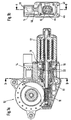
- FIGs 1a and 1b an electric motor is shown in which a substantially rectangular printed circuit board 14 is disposed between a transmission housing 10 with a gear 11 and a pole housing 12.
- the pole housing 12 has been shortened so far that a seated on an armature shaft 15 commutator 16 projects beyond the pole housing 12.
- a brush holder 18, which is held by the pole housing 12 and the gear housing 10, carries brushes 22, which are in engagement with the commutator 16.
- FIG. 2 shows the brush holder 18 with the printed circuit board 14 in detail.
- the brush holder 18 has substantially three areas. One, held by the pole housing 12 and the gear housing 10, substantially round plastic ring 20 which is flattened on two opposite sides, a run parallel to the flattened sides out web 26, and a connector 28 which is supported by the web 26.
- the inner recess of the plastic ring 20 is provided with the reference numeral 21 in the following.
- the plug-in direction of the connector plug 28 is perpendicular to the web 26 and parallel to the axis of the armature shaft 15.
- the plugged into the brush holder 18 printed circuit board 14 extends from the plastic ring 20 via the web 26 to the connector 28 of the brush holder 18.
- all three areas , the plastic ring 20, the web 26 and the connector 28 has a continuous groove 27 ( Figure 6), in which the circuit board 14 is pocketed inserted.
- the circuit board 14 is seated so firmly in the brush holder 18 and extends in a plane parallel to the armature shaft 15 between the gear 11 and pole housing 12th
- the armature shaft 15 which carries the commutator 16.
- the inner recess 21 of the plastic ring 20 sit two opposite segments 29 of a tall cylinder ring, coaxial with the plastic ring 20.
- the foot brush holder 31 are arranged.
- the segments 29, ie at the end remote from the plastic ring 20 they form a bearing receptacle 32 for a spherical bearing which supports the armature shaft 15.
- the brushes 22 are arranged on the brush supports 31 such that they consist of recesses in protrude the segments 29 in the direction of the commutator 16, in particular by means not shown springs are pressed against the commutator 16.
- the suppressor 34 are arranged in the immediate vicinity of the brush 22 and the suppressor 34. These rest on retaining members 30 arranged on the brush holder 18, extend parallel to the brush holder 18 and are in direct contact with the printed circuit board 14.
- the circuit board 14 can be brought very close to the armature shaft 17 in that the brush holder 31 are arranged in the region of the segments 29.
- the suppression components 34 are arranged directly on the printed circuit board 14. As shown in the drawing, in particular, the coils or capacitors, which act as suppressors 34, protrude perpendicularly from the plane of the circuit board 14.
- the circuit board 14 can be fitted in a process with components of the control electronics and suppressor 34, whereby a subsequent soldering of the suppression 34 is omitted.
- a magnetic encoder 35 is additionally arranged between the commutator 16 and the bearing cup 37, which together with a arranged on the circuit board 14 Hall sensor 36 allows a position determination of the transmission 11.
- the magnetic encoder 35 consists of a hollow cylinder, for example, a hollow cylinder pressed onto the armature shaft 15 and having different polarities paired in several segments.
- a Hall sensor 36 is arranged on the circuit board 14 ASIC having an integrated Hall sensor. Of course, single or double-Hall sensors are also possible.
- the connecting bridges 38 can be connected to the printed circuit board 14, for example via a soldering process or via press-in techniques.
- gear housing 10 and brush holder 18 also have various fasteners such as teeth 40 for easy attachment of the gear housing 10.
- seals 48 may be arranged, which are molded for example by a multi-component injection process or are also designed as a separate sealing member.
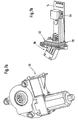
- FIG. 3 shows an electric motor with brush holder 18 and pole housing 12.
- the bearing cap 37 is arranged in the bearing receptacle 32 at the upper end of the segments 29.
- the magnetic encoder 35 is positioned.
- the armature shaft 15 itself is mounted so that it bounces at its armature-distal end and is provided on the armature side with a sliding or roller bearing.
- FIG. 4 shows an electric motor with brush holder 18, pole housing 12 and gear housing 10.
- Pol housing 12 and gear housing 10 are connected with three fastening elements at three connection points 46.
- the transmission housing 10 has clips 42 for connection to the teeth 40 of the brush holder 18.
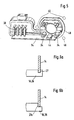
- Figure 5 shows a variation of the brush holder 18 with the connecting bridges 38, and the positions of the connecting points 46 of the pole housing 12 with the Gear housing 10. These are arranged in the form of an approximately isosceles triangle.
- an ASIC 44 is arranged with integrated Hall sensor.
- the suppression components 34 are arranged here in a cylinder-like shape of the brush holder 18 parallel to the armature shaft 15.
- FIG. 6 a shows a detail of a section through the web 26.
- the web 26 of the brush holder 18 has a groove 27 into which the circuit board 14 is inserted.
- FIG. 6b a variation is shown, in which the web 26 has, instead of the groove 27, a stop 27a for locking the printed circuit board 14.
- FIG. 7 a shows a variation of an electric motor according to the invention.
- the brush holder 18 is not visible here and has no web 26 with connector 28. Instead, the gear housing 10 has a lateral opening 50 into which a rectangular printed circuit board 14 can be inserted with the control electronics.
- the connector 28 is attached to one side via a connecting flange 52 to the circuit board 14.
- the printed circuit board 14 here has clamping electrodes 54 which are brought into engagement with corresponding mating contacts, for example on the brush holder 18, when the printed circuit board 14 is inserted into the opening 50 (FIG. 7a).
- this can for example by means of a groove, not shown here and / or corresponding stops in the transmission housing 10 in the correct position are pushed, or fixed in the intended position.
- the connecting flange 52 closes the gear housing via corresponding flange seals 56.
- the flange can be performed for example as a screw or clip connection.
Landscapes
- Engineering & Computer Science (AREA)
- Power Engineering (AREA)
- Motor Or Generator Frames (AREA)
- Connection Of Motors, Electrical Generators, Mechanical Devices, And The Like (AREA)
- Motor Or Generator Current Collectors (AREA)
- Window Of Vehicle (AREA)
Applications Claiming Priority (3)
| Application Number | Priority Date | Filing Date | Title |
|---|---|---|---|
| DE10007696 | 2000-02-19 | ||
| DE10007696A DE10007696A1 (de) | 2000-02-19 | 2000-02-19 | Elektromotoren, insbesondere zum Heben und Senken von Scheiben bei Kraftfahrzeugen |
| PCT/DE2000/004551 WO2001061828A1 (de) | 2000-02-19 | 2000-12-20 | Elektromotor, insbesondere zum heben und senken von scheiben bei kraftfahrzeugen |
Publications (2)
| Publication Number | Publication Date |
|---|---|
| EP1173918A1 EP1173918A1 (de) | 2002-01-23 |
| EP1173918B1 true EP1173918B1 (de) | 2007-06-06 |
Family
ID=7631607
Family Applications (1)
| Application Number | Title | Priority Date | Filing Date |
|---|---|---|---|
| EP00990556A Expired - Lifetime EP1173918B1 (de) | 2000-02-19 | 2000-12-20 | Elektromotor, insbesondere zum heben und senken von scheiben bei kraftfahrzeugen |
Country Status (7)
| Country | Link |
|---|---|
| US (1) | US6759783B2 (enExample) |
| EP (1) | EP1173918B1 (enExample) |
| JP (1) | JP4681195B2 (enExample) |
| KR (1) | KR100809306B1 (enExample) |
| DE (2) | DE10007696A1 (enExample) |
| ES (1) | ES2284553T3 (enExample) |
| WO (1) | WO2001061828A1 (enExample) |
Cited By (1)
| Publication number | Priority date | Publication date | Assignee | Title |
|---|---|---|---|---|
| CN106411041A (zh) * | 2015-06-17 | 2017-02-15 | 布洛泽汽车部件制造沃尔兹堡有限公司 | 驱动单元 |
Families Citing this family (52)
| Publication number | Priority date | Publication date | Assignee | Title |
|---|---|---|---|---|
| DE19924631A1 (de) * | 1999-05-29 | 2000-11-30 | Bosch Gmbh Robert | Kommutatormotor |
| DE10006350A1 (de) * | 2000-02-12 | 2001-08-16 | Bosch Gmbh Robert | Elektrischer Antrieb, insbesondere für Kraftfahrzeuge |
| US6756711B2 (en) | 2000-12-27 | 2004-06-29 | Asmo Co., Ltd. | Motor having control circuit board for controlling its rotation |
| DE10207004A1 (de) * | 2002-02-19 | 2003-08-28 | Bosch Gmbh Robert | Antriebsvorrichtung |
| AU2003255141A1 (en) | 2002-08-30 | 2004-03-29 | Asmo Co., Ltd. | Motor |
| JP3934523B2 (ja) * | 2002-10-08 | 2007-06-20 | アスモ株式会社 | モータ |
| JP3940059B2 (ja) * | 2002-10-22 | 2007-07-04 | アスモ株式会社 | モータ |
| DE102004012355A1 (de) * | 2003-03-18 | 2004-09-30 | Continental Teves Ag & Co. Ohg | Betätigungseinheit für eine elektromechanisch betätigbare Scheibenbremse |
| DE10318062A1 (de) * | 2003-04-17 | 2004-11-11 | Robert Bosch Gmbh | Getriebe-Antriebseinheit mit Elektronik-Schnittstelle |
| DE10331238A1 (de) * | 2003-07-10 | 2005-02-03 | Robert Bosch Gmbh | Elektromotor mit mehrteiliger Leiterplatte |
| US7187095B2 (en) * | 2004-02-24 | 2007-03-06 | Asmo Co., Ltd. | Motor, control circuit member and manufacturing method of motor |
| DE102004034029A1 (de) * | 2004-07-13 | 2006-02-09 | Robert Bosch Gmbh | Elektrische Antriebseinheit mit mindestens zwei elektrischen Bauteilträgern, sowie Verfahren zum Herstellen einer solchen |
| TWI276269B (en) | 2004-08-18 | 2007-03-11 | Delta Electronics Inc | Connector module |
| CN1747255A (zh) * | 2004-09-06 | 2006-03-15 | 台达电子工业股份有限公司 | 连结器模块 |
| US7640826B2 (en) * | 2004-10-21 | 2010-01-05 | Continental Automotive Canada, Inc. | Actuator apparatus incorporating a controller |
| US7681474B2 (en) * | 2004-10-21 | 2010-03-23 | Continental Automotive Systems Us, Inc. | System for adjusting the pedals of a vehicle |
| DE102004057463A1 (de) | 2004-11-29 | 2006-06-01 | Robert Bosch Gmbh | Elektrische Maschine mit in das Gehäuse integrierten Leiterbahnen |
| JP4539383B2 (ja) * | 2005-03-14 | 2010-09-08 | トヨタ自動車株式会社 | 動力伝達装置のコントロールユニット取付構造 |
| DE102005012619A1 (de) * | 2005-03-18 | 2006-09-28 | Bühler Motor GmbH | Elektrischer Antrieb |
| JP4701980B2 (ja) * | 2005-10-13 | 2011-06-15 | 日本精工株式会社 | 電動パワーステアリング装置 |
| DE102005057398A1 (de) * | 2005-11-30 | 2007-05-31 | Robert Bosch Gmbh | Bürstenträger-Bauteil mit Masse-Kontaktblech |
| DE102005059051A1 (de) * | 2005-12-08 | 2007-06-14 | Kiekert Ag | Kompakter Schwenkantrieb für Fahrzeugklappen |
| FR2897484A1 (fr) * | 2006-02-15 | 2007-08-17 | Arvinmeritor Light Vehicle Sys | Dispositif d'entrainement, ouvrant de vehicule automobile et procede de realisation d'une ligne equipotentielle dans un dispositif d'entrainement |
| DE102007005572A1 (de) * | 2007-02-05 | 2008-08-07 | Robert Bosch Gmbh | Elektrischer Antrieb |
| TW200835118A (en) * | 2007-02-12 | 2008-08-16 | Delta Electronics Inc | Motor and stator structure thereof |
| JP5096939B2 (ja) * | 2008-01-21 | 2012-12-12 | 日本電産サンキョー株式会社 | モータ装置 |
| US7800252B2 (en) * | 2008-06-27 | 2010-09-21 | Igo, Inc. | Load condition controlled wall plate outlet system |
| JP5352353B2 (ja) | 2009-06-17 | 2013-11-27 | アスモ株式会社 | モータ |
| DE102009027610A1 (de) * | 2009-07-10 | 2011-01-13 | Robert Bosch Gmbh | Verstellantrieb, insbesondere Fensterheberantrieb |
| CN102044934B (zh) * | 2009-10-21 | 2014-10-22 | 德昌电机(深圳)有限公司 | 电机驱动组件 |
| CN102118078A (zh) * | 2009-12-30 | 2011-07-06 | 德昌电机(深圳)有限公司 | 电机驱动组件 |
| DE102010002511A1 (de) | 2010-03-02 | 2011-09-08 | Robert Bosch Gmbh | Verstellantrieb, insbesondere Fensterheberantrieb |
| JP5852846B2 (ja) | 2010-12-28 | 2016-02-03 | アスモ株式会社 | モータ |
| US8901800B2 (en) | 2010-12-28 | 2014-12-02 | Asmo Co., Ltd. | Motor |
| WO2013065736A1 (ja) * | 2011-11-04 | 2013-05-10 | 株式会社ミツバ | 電動モータ装置及びその組み立て方法 |
| DE102012216946A1 (de) | 2012-09-21 | 2014-03-27 | Robert Bosch Gmbh | Bürstenträger für einen Elektromotor, Elektromotor sowie Antriebsaggregat |
| JP6219028B2 (ja) * | 2012-10-29 | 2017-10-25 | アスモ株式会社 | 制御回路付きモータ |
| US9114798B1 (en) | 2012-12-12 | 2015-08-25 | Hydro-Gear Limited Partnership | Electric actuator for drive apparatus |
| DE102013202857A1 (de) * | 2013-02-21 | 2014-08-21 | Robert Bosch Gmbh | Bürstenträger für einen Elektromotor und Getriebe-Antriebseinheit mit einem Bürstenträger |
| JP6262457B2 (ja) * | 2013-07-11 | 2018-01-17 | 株式会社ミツバ | 電動モータ |
| CN108418378B (zh) | 2013-07-11 | 2020-04-17 | 株式会社美姿把 | 带减速机构的电动机 |
| JP6082680B2 (ja) * | 2013-09-18 | 2017-02-15 | アスモ株式会社 | モータ |
| DE102014201182A1 (de) * | 2014-01-23 | 2015-07-23 | Robert Bosch Gmbh | Antriebseinrichtung für eine Scheibenwischeinrichtung |
| DE102014225357B4 (de) * | 2014-12-10 | 2022-09-08 | Robert Bosch Gmbh | Getriebe-Antriebseinrichtung |
| KR102408251B1 (ko) * | 2015-10-01 | 2022-06-13 | 엘지이노텍 주식회사 | 파킹 브레이크 액츄에이터 |
| DE102015122095A1 (de) * | 2015-12-17 | 2017-06-22 | Valeo Systèmes d'Essuyage | Anschlusseinheit für einen Wischermotor für Scheibenwischanlagen und Wischermotor |
| CN109302001B (zh) * | 2017-07-25 | 2022-05-31 | 德昌电机(深圳)有限公司 | 驱动装置、致动器及车辆摇窗机构 |
| JP6442031B2 (ja) * | 2017-12-13 | 2018-12-19 | 株式会社ミツバ | 電動モータ |
| DE102019102536A1 (de) * | 2019-02-01 | 2020-08-06 | Nidec Motors & Actuators (Germany) Gmbh | Verstellantrieb aufweisend eine Bürstenkartenanordnung mit integrierter Leiterplatte |
| DE202019103356U1 (de) * | 2019-06-14 | 2020-09-15 | Dewertokin Gmbh | Entstörter Linearantrieb |
| CN113394922B (zh) * | 2020-03-13 | 2022-06-14 | 中车永济电机有限公司 | 永磁电机调整方法、装置、设备以及存储介质 |
| DE102021132129A1 (de) * | 2021-12-07 | 2023-06-07 | Kiekert Aktiengesellschaft | Stellantrieb für kraftfahrzeugtechnische Anwendungen |
Family Cites Families (19)
| Publication number | Priority date | Publication date | Assignee | Title |
|---|---|---|---|---|
| DE4005709A1 (de) * | 1990-02-23 | 1991-09-05 | Bosch Gmbh Robert | Elektromotorischer antrieb |
| DE59006639D1 (de) | 1990-09-12 | 1994-09-01 | Siemens Ag | Kommutator-Getriebe-Antriebseinheit, insbesondere Fensterheberantrieb für ein Kraftfahrzeug, und Verfahren zu deren Herstellung. |
| GB2270568A (en) * | 1992-09-15 | 1994-03-16 | Crane Electronics | Torque transducer having a slipring and brush assembly |
| DE4233156A1 (de) | 1992-10-02 | 1994-04-07 | Bosch Gmbh Robert | Elektromotorischer Antrieb |
| ES2066624T5 (es) * | 1993-03-31 | 2001-11-01 | Siemens Ag | Unidad de accionamiento con engranaje y motor de conmutador, en especial accionamiento para elevalunas de vehiculos de motor. |
| DE4315404A1 (de) * | 1993-05-08 | 1994-11-10 | Bosch Gmbh Robert | Elektromotorischer Antrieb zum Verstellen von Ausstattungsteilen eines Kraftfahrzeuges |
| US5942819A (en) * | 1996-03-15 | 1999-08-24 | Alcoa Fujikura Ltd. | Motor brush assembly with noise suppression |
| JP3622362B2 (ja) | 1996-09-19 | 2005-02-23 | 株式会社デンソー | 電動式パワーステアリング装置 |
| DE19710015A1 (de) * | 1997-03-12 | 1998-09-17 | Bosch Gmbh Robert | Motor mit Drehzahlabgriff über einen Hall-Sensor |
| DE19710014A1 (de) * | 1997-03-12 | 1998-09-17 | Bosch Gmbh Robert | Kommutatormotor |
| US6252938B1 (en) * | 1997-06-19 | 2001-06-26 | Creatv Microtech, Inc. | Two-dimensional, anti-scatter grid and collimator designs, and its motion, fabrication and assembly |
| DE19727118A1 (de) * | 1997-06-26 | 1999-01-28 | Bosch Gmbh Robert | Elektrische Antriebseinheit |
| GB9715338D0 (en) | 1997-07-21 | 1997-09-24 | Amp Holland | A unit for controlling electrical motors |
| JPH1198768A (ja) * | 1997-09-16 | 1999-04-09 | Asmo Co Ltd | モータ |
| DE19805185A1 (de) * | 1998-02-10 | 1999-08-12 | Bosch Gmbh Robert | Antriebsvorrichtung, insbesondere zum Verstellen eines Schiebedachs eines Fahrzeugs |
| DE19858233A1 (de) * | 1998-12-17 | 2000-06-29 | Bosch Gmbh Robert | Elektrischer Getriebemotor für Fahrzeugaggregate |
| DE19963158A1 (de) * | 1999-12-24 | 2001-06-28 | Valeo Auto Electric Gmbh | Getriebemotor, insbesondere Wischergetriebemotor für ein Fahrzeug |
| US6481550B2 (en) * | 2000-07-25 | 2002-11-19 | Asmo Co., Ltd. | Motor having clutch provided with stopper |
| US6525938B1 (en) * | 2002-01-02 | 2003-02-25 | Yen Sun Technology Corp. | Circuit board fixing structure of heatsink fan |
-
2000
- 2000-02-19 DE DE10007696A patent/DE10007696A1/de not_active Withdrawn
- 2000-12-20 WO PCT/DE2000/004551 patent/WO2001061828A1/de not_active Ceased
- 2000-12-20 DE DE50014388T patent/DE50014388D1/de not_active Expired - Lifetime
- 2000-12-20 EP EP00990556A patent/EP1173918B1/de not_active Expired - Lifetime
- 2000-12-20 KR KR1020017013271A patent/KR100809306B1/ko not_active Expired - Fee Related
- 2000-12-20 ES ES00990556T patent/ES2284553T3/es not_active Expired - Lifetime
- 2000-12-20 JP JP2001560512A patent/JP4681195B2/ja not_active Expired - Fee Related
- 2000-12-20 US US10/030,872 patent/US6759783B2/en not_active Expired - Lifetime
Cited By (1)
| Publication number | Priority date | Publication date | Assignee | Title |
|---|---|---|---|---|
| CN106411041A (zh) * | 2015-06-17 | 2017-02-15 | 布洛泽汽车部件制造沃尔兹堡有限公司 | 驱动单元 |
Also Published As
| Publication number | Publication date |
|---|---|
| DE10007696A1 (de) | 2001-08-23 |
| JP2003523708A (ja) | 2003-08-05 |
| DE50014388D1 (de) | 2007-07-19 |
| KR100809306B1 (ko) | 2008-03-04 |
| EP1173918A1 (de) | 2002-01-23 |
| WO2001061828A1 (de) | 2001-08-23 |
| JP4681195B2 (ja) | 2011-05-11 |
| ES2284553T3 (es) | 2007-11-16 |
| KR20010112942A (ko) | 2001-12-22 |
| US20020149283A1 (en) | 2002-10-17 |
| US6759783B2 (en) | 2004-07-06 |
Similar Documents
| Publication | Publication Date | Title |
|---|---|---|
| EP1173918B1 (de) | Elektromotor, insbesondere zum heben und senken von scheiben bei kraftfahrzeugen | |
| EP0993696B1 (de) | Antriebsvorrichtung, insbesondere zum verstellen eines schiebedachs eines fahrzeugs | |
| EP1171680B1 (de) | Motorgehäuse und poltopf, insbesondere für fensterheber- oder schiebedachmotoren | |
| EP1095443A1 (de) | Stellantrieb mit einem elektromotor und mit einer steuerelektronik | |
| DE19858233A1 (de) | Elektrischer Getriebemotor für Fahrzeugaggregate | |
| DE102014212135B4 (de) | Getriebe-Antriebseinrichtung und Verfahren zur Montage einer Getriebe-Antriebseinrichtung | |
| DE69209710T2 (de) | Befestigungsvorrichtung einer Drosselspule für Kleinstmotoren | |
| DE102012213234A1 (de) | Verstellantrieb | |
| DE9013006U1 (de) | Kommutator-Getriebe-Antriebseinheit, insbesondere Fensterheberantrieb für ein Kraftfahrzeug | |
| DE10010439C2 (de) | Stellantrieb bzw. Verfahren zur Montage eines Stellantriebs | |
| DE102012104259B4 (de) | Gleichstrommotor zum Antrieb von Aggregaten eines Kraftfahrzeugs | |
| DE3432856C2 (enExample) | ||
| DE10249683B4 (de) | Kontaktklemme zur elektr. Kontaktierung eines Gegenkontaktes, insb. für den Einsatz bei elektrischen Kraftfahrzeugkomponenten, wie bspw. Fensterhebersystemen o. dgl. | |
| DE3035414C2 (de) | Elektrischer Kleinmotor mit einem kastenförmigen Gehäuserahmen | |
| DE102010009805B4 (de) | Steckbrücke | |
| DE10118387A1 (de) | Getriebe, insbesondere Schneckengetriebe | |
| EP0655173B1 (de) | Vorrichtung zur verbindung eines motors mit wenigstens zwei elektrischen leiterbahnen | |
| DE3618177A1 (de) | Halterung fuer einen elektromotor, insbesondere fuer ein geblaese | |
| DE4116100A1 (de) | Motor-getriebeeinheit, insbesondere fuer eine scheibenwischeranlage | |
| EP1247314A1 (de) | Mit einer platine abgewinkelt mechanisch fixierbare und elektrisch kontaktierbare steckereinheit | |
| DE102008053036A1 (de) | Antriebsbaugruppe für die motorische Verstellung eines Verstellelements in einem Kraftfahrzeug | |
| DE102004036419B4 (de) | Elektromotorischer Hilfsantrieb | |
| WO2019086066A1 (de) | Steckverbinder | |
| DE19858231A1 (de) | Elektrische Antriebseinheit für Fahrzeugaggregate | |
| EP1935077A1 (de) | Elektromotor mit hammerbürsten |
Legal Events
| Date | Code | Title | Description |
|---|---|---|---|
| PUAI | Public reference made under article 153(3) epc to a published international application that has entered the european phase |
Free format text: ORIGINAL CODE: 0009012 |
|
| AK | Designated contracting states |
Kind code of ref document: A1 Designated state(s): AT BE CH CY DE DK ES FI FR GB GR IE IT LI LU MC NL PT SE TR |
|
| AX | Request for extension of the european patent |
Free format text: AL;LT;LV;MK;RO;SI |
|
| 17P | Request for examination filed |
Effective date: 20020225 |
|
| RBV | Designated contracting states (corrected) |
Designated state(s): DE ES FR GB IT |
|
| 17Q | First examination report despatched |
Effective date: 20060706 |
|
| GRAP | Despatch of communication of intention to grant a patent |
Free format text: ORIGINAL CODE: EPIDOSNIGR1 |
|
| GRAS | Grant fee paid |
Free format text: ORIGINAL CODE: EPIDOSNIGR3 |
|
| GRAA | (expected) grant |
Free format text: ORIGINAL CODE: 0009210 |
|
| AK | Designated contracting states |
Kind code of ref document: B1 Designated state(s): DE ES FR GB IT |
|
| REG | Reference to a national code |
Ref country code: GB Ref legal event code: FG4D Free format text: NOT ENGLISH |
|
| REF | Corresponds to: |
Ref document number: 50014388 Country of ref document: DE Date of ref document: 20070719 Kind code of ref document: P |
|
| ET | Fr: translation filed | ||
| REG | Reference to a national code |
Ref country code: ES Ref legal event code: FG2A Ref document number: 2284553 Country of ref document: ES Kind code of ref document: T3 |
|
| GBV | Gb: ep patent (uk) treated as always having been void in accordance with gb section 77(7)/1977 [no translation filed] |
Effective date: 20070606 |
|
| PLBE | No opposition filed within time limit |
Free format text: ORIGINAL CODE: 0009261 |
|
| STAA | Information on the status of an ep patent application or granted ep patent |
Free format text: STATUS: NO OPPOSITION FILED WITHIN TIME LIMIT |
|
| PG25 | Lapsed in a contracting state [announced via postgrant information from national office to epo] |
Ref country code: GB Free format text: LAPSE BECAUSE OF FAILURE TO SUBMIT A TRANSLATION OF THE DESCRIPTION OR TO PAY THE FEE WITHIN THE PRESCRIBED TIME-LIMIT Effective date: 20070606 |
|
| 26N | No opposition filed |
Effective date: 20080307 |
|
| REG | Reference to a national code |
Ref country code: FR Ref legal event code: PLFP Year of fee payment: 16 |
|
| REG | Reference to a national code |
Ref country code: FR Ref legal event code: PLFP Year of fee payment: 17 |
|
| PGFP | Annual fee paid to national office [announced via postgrant information from national office to epo] |
Ref country code: IT Payment date: 20161220 Year of fee payment: 17 Ref country code: FR Payment date: 20161221 Year of fee payment: 17 Ref country code: ES Payment date: 20161221 Year of fee payment: 17 |
|
| PGFP | Annual fee paid to national office [announced via postgrant information from national office to epo] |
Ref country code: DE Payment date: 20170224 Year of fee payment: 17 |
|
| REG | Reference to a national code |
Ref country code: DE Ref legal event code: R119 Ref document number: 50014388 Country of ref document: DE |
|
| REG | Reference to a national code |
Ref country code: FR Ref legal event code: ST Effective date: 20180831 |
|
| PG25 | Lapsed in a contracting state [announced via postgrant information from national office to epo] |
Ref country code: IT Free format text: LAPSE BECAUSE OF NON-PAYMENT OF DUE FEES Effective date: 20171220 Ref country code: FR Free format text: LAPSE BECAUSE OF NON-PAYMENT OF DUE FEES Effective date: 20180102 Ref country code: DE Free format text: LAPSE BECAUSE OF NON-PAYMENT OF DUE FEES Effective date: 20180703 |
|
| REG | Reference to a national code |
Ref country code: ES Ref legal event code: FD2A Effective date: 20190703 |
|
| PG25 | Lapsed in a contracting state [announced via postgrant information from national office to epo] |
Ref country code: ES Free format text: LAPSE BECAUSE OF NON-PAYMENT OF DUE FEES Effective date: 20171221 |