EP1173009A1 - Bildaufnahmevorrichtung und tragbares Telefon dieselbe einbeziehend - Google Patents
Bildaufnahmevorrichtung und tragbares Telefon dieselbe einbeziehend Download PDFInfo
- Publication number
- EP1173009A1 EP1173009A1 EP01114596A EP01114596A EP1173009A1 EP 1173009 A1 EP1173009 A1 EP 1173009A1 EP 01114596 A EP01114596 A EP 01114596A EP 01114596 A EP01114596 A EP 01114596A EP 1173009 A1 EP1173009 A1 EP 1173009A1
- Authority
- EP
- European Patent Office
- Prior art keywords
- light
- image pick
- image
- receiving surface
- lens mount
- Prior art date
- Legal status (The legal status is an assumption and is not a legal conclusion. Google has not performed a legal analysis and makes no representation as to the accuracy of the status listed.)
- Withdrawn
Links
Images


Classifications
-
- H—ELECTRICITY
- H04—ELECTRIC COMMUNICATION TECHNIQUE
- H04N—PICTORIAL COMMUNICATION, e.g. TELEVISION
- H04N7/00—Television systems
- H04N7/14—Systems for two-way working
- H04N7/141—Systems for two-way working between two video terminals, e.g. videophone
- H04N7/142—Constructional details of the terminal equipment, e.g. arrangements of the camera and the display
-
- H—ELECTRICITY
- H04—ELECTRIC COMMUNICATION TECHNIQUE
- H04N—PICTORIAL COMMUNICATION, e.g. TELEVISION
- H04N23/00—Cameras or camera modules comprising electronic image sensors; Control thereof
-
- H—ELECTRICITY
- H04—ELECTRIC COMMUNICATION TECHNIQUE
- H04N—PICTORIAL COMMUNICATION, e.g. TELEVISION
- H04N23/00—Cameras or camera modules comprising electronic image sensors; Control thereof
- H04N23/50—Constructional details
- H04N23/55—Optical parts specially adapted for electronic image sensors; Mounting thereof
-
- H—ELECTRICITY
- H04—ELECTRIC COMMUNICATION TECHNIQUE
- H04N—PICTORIAL COMMUNICATION, e.g. TELEVISION
- H04N23/00—Cameras or camera modules comprising electronic image sensors; Control thereof
- H04N23/58—Means for changing the camera field of view without moving the camera body, e.g. nutating or panning of optics or image sensors
-
- H—ELECTRICITY
- H04—ELECTRIC COMMUNICATION TECHNIQUE
- H04N—PICTORIAL COMMUNICATION, e.g. TELEVISION
- H04N7/00—Television systems
- H04N7/14—Systems for two-way working
- H04N7/141—Systems for two-way working between two video terminals, e.g. videophone
- H04N7/142—Constructional details of the terminal equipment, e.g. arrangements of the camera and the display
- H04N2007/145—Handheld terminals
Definitions
- the present invention relates to an image pick-up apparatus for picking up object information from different directions on a light-receiving surface of one image pick-up device with a plurality of image forming lenses, and a portable telephone utilizing the image pick-up apparatus.
- the conventional image pick-up apparatuses of the above-mentioned type include, for instance, those having a structure shown in Figs. 25A and 25B.
- Fig. 25A shows a front view and a side view of the conventional image pick-up apparatus
- Fig. 25B is a phantom diagram of the side view.
- the image pick-up apparatus includes an image forming lens 2, lens-barrels 101 and 102, and a package 13.
- Package 13 is box-like and its interior has a cavity structure, and an image pick-up device 3 having a light-receiving surface 3a is mounted in the cavity portion.
- image pick-up device 3 is electrically connected to a circuit pattern portion integrally provided to package 13 by wire bonding packaging and the like, not shown, and further, a space in which image pick-up device 3 is disposed is sealed with a translucent plate 4.
- Lens-barrel 102 is fixed to package 13 using an adhesive or the like, not shown, and is assembled with lens-barrel 101 by a screw portion, not shown. Lens-barrels 101 and 102 are formed such that focus adjustment of image forming lens 2 can be performed using the screw portion, not shown.
- object information is condensed by image forming lens 2 and image is formed on light-receiving surface 3a portion on image pick-up device 3.
- the information of an object formed as image on light-receiving surface 3a is subjected to a photoelectric conversion and is output as an electrical signal.
- the conventional image pick-up apparatus is configured in the above-described manner so that, in the case of a digital camera and the like, there is a need to position a monitor portion, which shows the picked-up image, on the opposite surface from the direction which the image pick-up apparatus faces in order to allow the user to confirm the condition in which the picked-up image is picked up within a monitor frame.
- possible uses include transmitting and receiving a picked-up image on a communication link of the portable telephones, and two kinds of usage are possible: picking up an image of a self-portrait and transferring data thereof; and picking up an image of an object in the surroundings, for instance, an object in the opposite direction, and transferring data thereof.
- Portable equipment as represented by portable telephones is daily subjected to extremely bad conditions of use such as dropping of the equipment and application of pressure which do not normally occur with electrical equipment. It is, therefore, not desirable to provide a mechanical operating portion such as a rotational portion on a location that is exposed on the outside from the viewpoint of structural strength.
- the equipment provided with the image pick-up apparatus itself must be directed toward the object upon performing image pick-up of the opposite direction. Under this circumstance, however, the condition of the picked-up image shown on a display portion of the portable telephone cannot be confirmed so that it is difficult, for instance, to make an adjustment to locate the object in the central portion of a screen.
- an image pick-up apparatus which allows image pick-up of object information from two different directions using one image pick-up device, a beam reflecting component such as a prism mirror, and two image forming lenses, and which performs image pick-up of one of the two directions by reflecting an optical path with the prism mirror.
- an external shutter or the like switch the direction of image pick-up to either one of the two directions, or that the object information from the two directions be separated inside the image pick-up apparatus by providing a structure such as a divider plate for separating the light regions of the respective object information such that the object information from two different directions do not interfere with one another while object information from both directions are constantly being picked up.
- One object of the present invention is to provide an image pick-up apparatus that is capable of picking up images from different directions using one image pick-up device while eliminating the need to switch the image pick-up directions with an external mechanism, and a further object is to provide a portable telephone incorporating such an apparatus.
- an image pick-up apparatus includes an image pick-up device having a light-receiving surface, a first image forming lens for forming as an image on the light-receiving surface a first light entering from a first direction toward the light-receiving surface, a second image forming lens for forming as an image on the light-receiving surface a second light entering from a second direction different from the first direction toward the light-receiving surface, an optical member for changing a direction of travel of at least one of the first light and the second light to a direction perpendicular to the light-receiving surface, and a lens mount for holding the optical member and having the first and second image forming lenses mounted thereto.
- the first image forming lens preferably forms an image on a first light region of the light-receiving surface
- the second image forming lens preferably forms an image on a second light region of the light-receiving surface
- a light region separating member is provided between the first and second light regions.
- the light region separating member preferably is continuously formed with the lens mount.
- a translucent plate for blocking at least one of infrared light and ultraviolet light preferably is provided on the light-receiving surface, and the light region separating member is fixed to the translucent plate.
- the light region separating member preferably is molded integrally with the lens mount.
- the translucent plate preferably is divided so as to sandwich the light region separating member therebetween.
- the first and second image forming lenses preferably are disposed such that the first and second light regions are located diagonally on the light-receiving surface.
- a translucent plate for blocking at least one of infrared light and ultraviolet light preferably is provided on the light-receiving surface, and the translucent plate is incorporated into the lens mount by abutting the translucent plate against an abutting portion provided on the lens mount.
- the lens mount preferably is formed of a material having a light blocking characteristic.
- the lens mount preferably forms a sealed structure for inhibiting intrusion of foreign substance onto the light-receiving surface from outside together with the first and second image forming lenses.
- a translucent plate for blocking at least one of infrared light and ultraviolet light preferably is provided on the light-receiving surface, the lens mount has a reservoir portion for an adhesive, and the translucent plate is fixed to the lens mount by providing an adhesive to the reservoir portion.
- the lens mount preferably includes a taper portion, and the taper portion is formed such that it separates optical paths from the first and second image forming lenses in a vicinity of the light-receiving surface and that it has an opening that becomes larger toward the light-receiving surface.
- the image pick-up device preferably is abutted against and fixed to the lens mount, and a reference plane for allowing at least one of the first and second image forming lenses to form an image on the light-receiving surface is formed in a portion where the image pick-up device abuts against the lens mount.
- the lens mount preferably has a box-like depressed portion on a bottom surface, the image pick-up device is fixed within the depressed portion, and a gap of the depressed portion is filled with sealing resin.
- the lens mount and the image pick-up device preferably are connected via a frame-like component, and the frame-like component has a divider portion for dividing optical paths from the first and second image forming lenses and has a translucent plate for blocking at least one of infrared light and ultraviolet light in each of the optical paths divided by the divider portion.
- an abutting surface for allowing parallel disposition of the translucent plate and the image pick-up device is preferably formed on the frame-like component.
- the frame-like component preferably has a positioning stopper, and the lens mount has a portion that is stopped by the stopper.
- a portable telephone according to the present invention incorporates one of the above-described image pick-up devices.
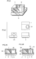
- Figs. 1 and 2 are a perspective view of an image pick-up apparatus according to the present invention and a development diagram of an exterior portion thereof.
- the image pick-up apparatus includes a lens mount 1, an image forming lens 2 incorporated into lens mount 1, image forming lenses 201, 202 for picking up images from different directions, and an image pick-up device 3.
- Figs. 3A and 3B are cross sectional block diagrams of the image pick-up apparatus according to the present invention.
- the image pick-up apparatus includes lens mount 1, image pick-up device 3, a prism mirror 6, an image forming lens 201 for picking up an image in a direction of the normal to image pick-up device 3, an image forming lens 202 for picking up an image in a horizontal direction to image pick-up device 3 via prism mirror 6, a light-receiving surface 3a formed on image pick-up device 3, a translucent plate 4, and a divider plate 5 for separating light regions of optical information from different directions obtained from image forming lens 201 and image forming lens 202.
- Fig. 3B shows an optical path 701 in a direction of the normal from image forming lens 201 and an optical path 702 from a horizontal direction from image forming lens 202.
- object information from the horizontal direction is reflected by prism mirror 6 and is formed as image on light-receiving surface 3a on image pick-up device 3.
- luminous flux of optical path 701 and luminous flux of optical path 702 do not interfere with one another since divider plate 5 separates the light regions.
- possible methods of electrical connection between an electrical circuit portion and image pick-up device 3 include wire bonding method, flip chip bonding method, and the like.
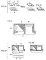
- FIGS. 4A, 4B, and 4C are explanatory diagrams related to the description of a step of inserting divider plate 5 in between translucent plates 401 and 402 formed by two-part division and disposing them on light-receiving surface 3a of image pick-up device 3.
- translucent plates 401 and 402 are formed by division and divider plate 5 is sandwiched between translucent plates 401 and 402 formed by division.
- the image pick-up apparatus of the present invention When the image pick-up apparatus of the present invention is mounted on such equipment as a portable telephone, it is desirable that a mechanical external shutter mechanism is not provided in view of a structural strength requirement of such equipment. Therefore, switching of image forming lenses with an external shutter is not performed, and object information via image forming lenses 201 and 202 are constantly formed as images on image pick-up device 3.
- switching between optical information to be shown on a liquid crystal monitor of the portable telephone is effected by a software, and the optical information is selected through a user key operation and the like.
- divider plate 5 separates the light regions and which is capable of image pick-up from at least two directions using one image pick-up device 3 and at least two image forming lenses 201 and 202 has been described. Since a light beam does not enter into a region in which divider plate 5 overlaps with light-receiving surface 3a of image pick-up device 3, this region cannot be used as an effective light-receiving region so that it is desirable that the thickness of divider plate 5 is as thin as possible. If, however, divider plate 5 is formed as a minute, thin component, the arrangement shown in Figs. 4A, 4B and 4C would, in turn, suffer degradation in productivity. Fig.
- FIG. 5 is a cross sectional block diagram related to the description of an arrangement of a lens mount incorporating image forming lenses 201 and 202 in the image pick-up apparatus according to the present invention.
- a divider plate portion 501 is integrally formed by connecting divider plate 5 shown in Fig. 4 with lens mount 1. It is possible to mold divider plate portion 501 to have a thickness that is as thin as 0.1 mm to 0.2 mm.
- Figs. 6A and 6B are cross sectional block diagrams showing image pick-up device 3 of the image pick-up apparatus according to the present invention prior mounting image pick-up device 3 on a lens mount and after mounting image pick-up device 3 on the lens mount, respectively. As shown in Figs. 6A and 6B in order, image pick-up device 3 is assembled by disposing translucent plates 401 and 402 formed by division which correspond to optical paths by image forming lenses 201 and 202 such that they sandwich divider plate portion 501 of lens mount 1.
- divider plate portion 501 which is a light region separating member is integrally molded with lens mount 1 so that assembly, for instance, of a two-direction image pick-up apparatus becomes easy and productivity can be improved.
- lens mount 1 is a molded part, and as long as its molding material has a light blocking characteristic, has low thermal expansion coefficient, is shock-resistant, has low hygroscopicity, and has a magnetic shielding function and the like, the image pick-up apparatus can be operated with stable performance even in the operating environment of portable equipment when lens mount 1 is mounted on such equipment as a portable telephone.
- translucent plate 4 can be a component having optical characteristics that allows blocking of an infrared light range or ultraviolet rays, or that allows improved light transmittance. In this way, since a need for separate provision of such optical functional components can be eliminated, the number of components and the production manhours can be reduced, while at the same time, the image pick-up apparatus can be built in a smaller scale while having the functions of such optical characteristics.
- Figs. 7A, 7B, and 7C are, respectively, a perspective view showing the image pick-up apparatus according to the second embodiment, a perspective view showing a lens mount 1 and an image pick-up device 3 being disassembled, and respective front views showing the disassembled lens mount 1 and image pick-up device 3.
- Figs. 8A and 8B show, respectively, a front view, side view, and a back view of lens mount 1, and an enlarged view of the back view.
- Figs. 9A and 9B each show a back view of lens mount 1 and a front view of image pick-up device 3.
- Figs. 7A, 7B, and 7C are, respectively, a perspective view showing the image pick-up apparatus according to the second embodiment, a perspective view showing a lens mount 1 and an image pick-up device 3 being disassembled, and respective front views showing the disassembled lens mount 1 and image pick-up device 3.
- Figs. 8A and 8B show, respectively, a front view, side view, and
- Image circles 801 and 802 are image circles of object information formed as images by image forming lens 201 and an image forming lens, not shown, respectively.
- Image circle 801 corresponds to image forming lens 201
- image circle 802 corresponds to an image forming lens 202.
- a portion 501 shown as a diagonally shaded portion in Figs. 8B, 9A, and 9B corresponds to a divider portion integrally formed with lens mount 1.
- image forming lenses 201 and 202 are disposed such that image circles 801 and 802 are located diagonally on light-receiving surface 3a of image pick-up device 3. Since, in Fig. 9B, image forming lenses 201 and 202 are disposed such that image circles 801 and 802 on light-receiving surface 3a of image pick-up device 3 are located linearly, divider portion 501 of lens mount 1 need to be formed over a longer range than that shown in Fig. 9A.
- divider portion 501 that is a light region separating member is integrally molded with lens mount 1.
- divider portion 501 is required to be formed as a thin-walled structure so that formation of divider portion 501 by molding becomes difficult when the range of the structure is long.
- image forming lenses 201 and 202 are disposed such that two image circles are located diagonally on light-receiving surface 3a of image pick-up device 3 so that the range of the divider portion required to have a thin-walled structure can be made to be of a minute length, and productivity can be improved when the divider portion is integrally molded with the lens mount.
- Figs. 10A and 10B are, respectively, a back view of a lens mount 1 of an image pick-up apparatus according to the third embodiment and an explanatory diagram showing translucent plates 401 and 402 incorporated into lens mount 1.
- Figs. 11A and 11B are a phantom diagram and a cross sectional view of lens mount 1, seen from different sides, respectively.
- the same reference characters as those appearing in the first and second embodiments indicate the same or corresponding parts in Figs. 10 and 11 so that the descriptions thereof will not be repeated.
- Fig. 10A shows an abutting portion 1a for improving the accuracy of parallelism with which translucent plates 401 and 402 are incorporated into lens mount 1.
- translucent plates 401 and 402 are incorporated into lens mount 1 by being abutted against abutting portions 1a, translucent plates 401 and 402 can be positioned perpendicular to an optical path 701 with high accuracy, as shown in Fig. 11B.
- translucent plates 401 and 402 are disposed out of perpendicular to optical path 701, in the optical path from image forming lens 201 to image pick-up device 3, the condition of light becomes non-uniform over the entire region of the optical path owing to the relationship between the space and a translucent plate portion having different refractive indices of light, thereby causing nonuniformity of resolution in an image pick-up apparatus in some cases.
- a translucent plate is not oblique in relation to the optical path but is disposed accurately orthogonal to the optical path so that stable performance and easy assembly of the image pick-up apparatus can be achieved.
- Figs. 12A and 12B are back views of a lens mount 1 of the image pick-up apparatus according to the fourth embodiment
- Fig. 13 is a phantom diagram of lens mount 1, seen from a side.
- the same reference characters as those appearing in the third embodiment indicate the same or corresponding parts in Figs. 12A, 12B, and 13 so that the descriptions thereof will not be repeated.
- a reservoir portion 1b is a portion for collecting the adhesive for fixing by adhesion to lens mount 1 translucent plates 401 and 402 which are disposed on lens mount 1.
- Fig. 12B is an explanatory diagram showing translucent plates 401 and 402 disposed on lens mount 1 and adhered thereto with an adhesive 9.
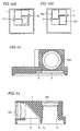
- Fig. 14 is a cross sectional block diagram of a lens mount 1 of the image pick-up apparatus according to the fifth embodiment, seen from a side.
- the same reference characters as those in the embodiments previously described indicate the same or corresponding parts in Fig. 14 so that the descriptions thereof will not be repeated.
- An internal structure of lens mount 1 is formed to have a taper portion 1c, as shown in Fig. 14.
- Taper portion 1c is formed on a divider portion that extends toward the vicinity of a light-receiving surface such that the light region of the light-receiving surface is divided into two parts.
- taper portion 1c is formed such that an opening toward image forming lens 201 becomes small while an opening toward the image pick-up device becomes large, whereas, in the optical path where light entering from image forming lens 202 is refracted on a prism mirror 6 such that the light enters in a direction orthogonal to the image pick-up device and leads up to the image pick-up device, taper portion 1c is formed such that an opening toward image forming lens 202 becomes small while an opening toward the image pick-up device becomes large.
- taper portion 1c is formed inside lens mount 1 so that, when molding lens mount 1, lens mount 1 which is a molded part can be easily released from a molding die, thereby allowing for easy molding of the divider portion which is a thin portion.
- taper portion 1c is formed inside lens mount 1, it becomes possible to form the inner wall portion of lens mount 1 to have a "rough surface" using the molding die so that diffuse reflection of light within lens mount 1 as well as degradation in quality such as flare of the image pick-up apparatus can be prevented.
- Figs. 15 is a cross sectional view of the image pick-up apparatus according to the sixth embodiment, seen from a side.
- Fig. 16 is a phantom view seen from the right side of Fig. 15.
- lens holders 10 are used in combination with image forming lenses 201 and 202.
- a screw portion 1d provided on a lens mount 1 and a screw portion 10a provided on a lens holder 10 are shown.
- a reference portion 1e is utilized to assemble lens mount 1 and an image pick-up device 3 by abutting lens mount 1 against image pick-up device 3.
- reference portion 1e of lens mount 1 is abutted against a portion other than light-receiving surface 3a of image pick-up device 3 for assembly so that lens mount 1 and image pick-up device 3 can be assembled with good relative positional accuracy in a direction of height with image pick-up device 3.
- image forming lens 202 is incorporated while effecting focus adjustment by screwing screw portion 10a provided on image forming lens holder 10 into screw portion 1d provided on lens mount 1.
- a focus adjustment mechanism of image forming lens 201 in a direction of the normal is eliminated.
- screw portion 10a is not provided to lens holder 10 of image forming lens 201, and a corresponding screw portion is not provided to lens mount 1.
- Image forming lens 201 and lens mount 1 are integrated by adhesion in advance using adhesive 9. Since reference portion 1e of lens mount 1 and image pick-up device 3 are abutted against one another and assembled as described above, the focal point of image forming lens 201 is determined by the molding accuracy of lens mount 1.
- a focal length of a lens can be made to be 5 mm or below, and molding variation of a lens mount in the image pick-up apparatus with a lens focal length of 5 mm can be made to be ⁇ 0.01 mm or below.
- the focal length of lens can be of sufficient accuracy even when adhesion variation of image forming lens 201 and lens mount 1 is taken into account.
- focus adjustment of image forming lens 201 becomes unnecessary in the image pick-up apparatus according to the sixth embodiment so that production of the image pick-up apparatus is facilitated.
- the adjustment in a direction of a focal point is described as unnecessary only for image forming lens 201 in the direction of the normal, focus adjustment in a horizontal direction can also be dispensed with.
- adjustment of image forming lenses 201 and 202 may be performed, and adjustment mechanism for both image forming lenses 201 and 202 may be retained.
- the relative positional relationship between lens mount 1 and image pick-up device 3 is made stable owing to the structure of abutting lens mount 1 and image pick-up device 3 against one another so that an adjustment range of image forming lenses 201 and 202 can be narrowed, which effectively reduces the time required for the adjustment.
- Fig. 17 is a phantom view, seen from a side, of the image pick-up apparatus according to the seventh embodiment.
- Fig. 18 is a phantom view of a lens mount 1 portion in Fig. 17, seen from a side.
- Fig. 18 shows two sidewall portions 1f provided to lens mount 1, although the two sides, not shown, orthogonal to sidewall portions 1f are formed in a similar manner.
- a cavity structure is formed by sidewall portions 1f formed on four sides seen from the bottom side of lens mount 1.
- sealing resin 11 is provided by potting or the like.
- Other parts denoted by the same reference characters as those in the embodiments previously described indicate the same or corresponding parts so that the descriptions thereof will not be repeated.
- a cavity is formed by sidewall portions 1f surrounding a bottom portion where image pick-up device 3 is disposed on lens mount 1, even when a liquid sealer for sealing image pick-up device 3 is provided, the liquid sealer can be prevented from flowing outward.
- provision of a sealer 11 for sealing image pick-up device 3 portion can be facilitated, which results in improved productivity.
- An overflow of sealing resin 11 can be prevented, and the quality in the external appearance of the image pick-up apparatus can be improved.
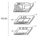
- Fig. 19 is a perspective view related to the description of the image pick-up apparatus according to the eighth embodiment.
- Fig. 20 is an exploded view related to the description of an arrangement of the image pick-up apparatus shown in Fig. 19.
- Figs. 19 and 20 show a lens mount 1, an image forming lens 2, an image pick-up device 3, a light-receiving surface 3a formed on image pick-up device 3, a frame-like component 12, and a divider portion 12a provided in a rib-like manner to frame-like component 12.
- Other parts denoted by the same reference characters as those in the embodiments previously described indicate the same or corresponding parts so that the descriptions thereof will not be repeated.
- two image forming lenses, not shown, are provided so as to allow two-direction image pick-up, and its operation principle is similar to as that of the above-described first embodiment.
- divider portion 12a which serves as a light region separating member that needs to be molded with a thin thickness is not integrally molded with lens mount 1 but is formed as a separate component on frame-like component 12 having a simple shape so that formation of divider portion 12a by molding is facilitated.
- Fig. 21A is a front view of frame-like component 12.
- Fig. 21B shows a cross sectional view taken along the line XXIB-XXIB in Fig. 21A and, below an arrow, a cross sectional block diagram representing image pick-up device 3 incorporated into frame-like component 12.
- an abutting surface 12b for incorporating a translucent plate 4 in an upper portion of frame-like component 12 and an abutting surface 12c for incorporating image pick-up device 3 in a lower portion of frame-like component 12 are formed on frame-like component 12.
- translucent plate 4 is formed by two translucent plates 401 and 402 formed by division, and incorporates divider portion 12a for light region separation in a so-called two-direction image pick-up by sandwiching divider portion 12a therebetween.
- translucent plates 401 and 402 disposed on frame-like component 12 and image pick-up device 3 disposed in a position opposite to translucent plates 401 and 402 are provided so that a surface portion including light-receiving surface 3a of image pick-up device 3 can be tightly sealed.
- an electrical connection member and a circuit board for operating image pick-up device 3 are not shown here, electrical connection is provided by wire bonding method, flip chip bonding method, and the like.
- configuration of divider portion 12a required for light region separation is facilitated while image pick-up device 3 can be sealed tightly so that improved reliability of the image pick-up apparatus itself can be achieved.
- a surface of image pick-up device 3 having light-receiving surface 3a and translucent plate 4 can be disposed with high accuracy of parallelism according to the molding accuracy of frame-like component 12, and variation in quality of the picked-up images due to variation in parallelism of translucent plate 4 having a different refractive index from air can be alleviated. Furthermore, it is possible to handle translucent plate 4 and image pick-up device 3 already being incorporated into frame-like component 12 on a production line so that the productivity improves.
- Fig. 23 is a cross sectional view of the image pick-up apparatus according to the ninth embodiment.
- Fig. 23 shows a protruded positioning portion 12d provided on frame-like component 12 and a depressed positioning portion 1g provided on lens mount 1.
- Other parts denoted by the same reference characters as those in the embodiments previously described indicate the same or corresponding parts so that the descriptions thereof will not be repeated.
- divider portion 12a which is a light region separating member provided to frame-like component 12 must be disposed with high accuracy in a central portion between image circles of two image forming lenses in a two-direction image pick-up apparatus
- divider portion can be easily registered with high accuracy by fitting together protruded positioning portion 12d provided on frame-like component 12 and depressed positioning portion 1g provided on lens mount 1 to assemble the image pick-up apparatus according to the ninth embodiment.
- a two-direction image pick-up apparatus that allows for mass production can be obtained by incorporating into a lens mount first and second image forming lenses for object information from different directions.
Applications Claiming Priority (2)
| Application Number | Priority Date | Filing Date | Title |
|---|---|---|---|
| JP2000187166A JP3848062B2 (ja) | 2000-06-22 | 2000-06-22 | 撮像装置及びこれを用いた携帯電話 |
| JP2000187166 | 2000-06-22 |
Publications (1)
| Publication Number | Publication Date |
|---|---|
| EP1173009A1 true EP1173009A1 (de) | 2002-01-16 |
Family
ID=18687190
Family Applications (1)
| Application Number | Title | Priority Date | Filing Date |
|---|---|---|---|
| EP01114596A Withdrawn EP1173009A1 (de) | 2000-06-22 | 2001-06-18 | Bildaufnahmevorrichtung und tragbares Telefon dieselbe einbeziehend |
Country Status (7)
| Country | Link |
|---|---|
| US (1) | US7030926B2 (de) |
| EP (1) | EP1173009A1 (de) |
| JP (1) | JP3848062B2 (de) |
| KR (1) | KR20020001553A (de) |
| CN (1) | CN1174649C (de) |
| NO (1) | NO20013171L (de) |
| TW (1) | TW578422B (de) |
Cited By (4)
| Publication number | Priority date | Publication date | Assignee | Title |
|---|---|---|---|---|
| DE10245085A1 (de) * | 2002-09-27 | 2004-04-01 | Automotive Distance Control Systems Gmbh | Optisches System für eine Kamera |
| US7499074B2 (en) | 2003-12-26 | 2009-03-03 | Lg Electronics Inc | Mobile communication device with enhanced image communication capability |
| GB2501688A (en) * | 2012-04-30 | 2013-11-06 | Flymount Ltd | Camera phone case for taking perpendicular pictures |
| US9065997B2 (en) | 2004-07-27 | 2015-06-23 | Lg Electronics Inc. | Image signal processing apparatus and method thereof in mobile communications terminal |
Families Citing this family (19)
| Publication number | Priority date | Publication date | Assignee | Title |
|---|---|---|---|---|
| JP2003060765A (ja) * | 2001-08-16 | 2003-02-28 | Nec Corp | カメラ付き携帯通信端末 |
| JP2003288161A (ja) | 2002-03-28 | 2003-10-10 | Nec Corp | 携帯機器 |
| JP3996498B2 (ja) | 2002-12-02 | 2007-10-24 | 株式会社オートネットワーク技術研究所 | カメラ装置及び車両周辺視認装置 |
| EP1471730A1 (de) * | 2003-03-31 | 2004-10-27 | Dialog Semiconductor GmbH | Miniaturkameramodul |
| US7619683B2 (en) * | 2003-08-29 | 2009-11-17 | Aptina Imaging Corporation | Apparatus including a dual camera module and method of using the same |
| JP4446773B2 (ja) * | 2004-03-26 | 2010-04-07 | 富士フイルム株式会社 | 撮影装置 |
| US20050264653A1 (en) * | 2004-05-27 | 2005-12-01 | Starkweather James A | Portable electronic device with adjustable image capture orientation and method therefore |
| EP1648181A1 (de) * | 2004-10-12 | 2006-04-19 | Dialog Semiconductor GmbH | Einzelbildabspeichervorrichtung |
| JP2007298873A (ja) | 2006-05-02 | 2007-11-15 | Pentax Corp | 樹脂製レンズの固定方法 |
| US7980773B2 (en) * | 2006-11-30 | 2011-07-19 | Hitachi Maxell, Ltd. | Camera module and imaging apparatus |
| JP5963421B2 (ja) * | 2011-11-17 | 2016-08-03 | オリンパス株式会社 | 固体撮像装置および撮像装置 |
| US9154677B2 (en) | 2012-09-20 | 2015-10-06 | Apple Inc. | Camera accessory for angled camera viewing |
| US10303910B2 (en) * | 2012-10-04 | 2019-05-28 | The Code Corporation | Apparatus comprising multiple sets of optics to facilitate capturing barcode and non-barcode images |
| US9153616B2 (en) * | 2012-12-26 | 2015-10-06 | Olympus Corporation | Solid-state imaging device and imaging device with circuit elements distributed on multiple substrates, method of controlling solid-state imaging device, and imaging device with circuit elements distributed on multiple substrates |
| JPWO2015133254A1 (ja) * | 2014-03-03 | 2017-04-06 | オリンパス株式会社 | 撮像装置、および内視鏡装置 |
| TWM523106U (zh) * | 2015-08-07 | 2016-06-01 | 高準精密工業股份有限公司 | 光學裝置 |
| CN107525805A (zh) * | 2016-06-20 | 2017-12-29 | 亿观生物科技股份有限公司 | 样本检测装置及样本检测系统 |
| CN107948478B (zh) * | 2017-12-06 | 2020-08-14 | 信利光电股份有限公司 | 一种潜望式变焦双摄像头模组及其加工方法 |
| US20210153725A1 (en) * | 2019-11-22 | 2021-05-27 | Lake Region Manufacturing, Inc. | Guidewire And Catheter System For In-Vivo Forward Viewing Of The Vasculature |
Citations (7)
| Publication number | Priority date | Publication date | Assignee | Title |
|---|---|---|---|---|
| JPS62224047A (ja) * | 1986-03-26 | 1987-10-02 | Hitachi Ltd | 固体撮像装置 |
| JPH01121725A (ja) * | 1987-11-05 | 1989-05-15 | Mitsubishi Electric Corp | 赤外線監視装置 |
| US4873572A (en) * | 1987-02-27 | 1989-10-10 | Olympus Optical Co., Ltd. | Electronic endoscope apparatus |
| WO1993011631A1 (en) * | 1991-12-06 | 1993-06-10 | Vlsi Vision Limited | Solid state sensor arrangement for video camera |
| EP0710039A2 (de) * | 1994-10-25 | 1996-05-01 | Kabushiki Kaisha Toshiba | Videokamera |
| US5644410A (en) * | 1993-03-19 | 1997-07-01 | Canon Kabushiki Kaisha | Image sensing apparatus |
| DE19736675A1 (de) * | 1997-08-22 | 1999-02-25 | Siemens Ag | Mobiles Bildtelefon |
Family Cites Families (17)
| Publication number | Priority date | Publication date | Assignee | Title |
|---|---|---|---|---|
| JPS6482860A (en) | 1987-09-25 | 1989-03-28 | Sony Corp | Method for forming reference surface of solid-state image pickup device fitting member |
| US5293243A (en) * | 1992-04-21 | 1994-03-08 | Degnan Donald E | Image splitter for security cameras |
| JPH07184102A (ja) | 1993-12-24 | 1995-07-21 | Sharp Corp | 撮像装置 |
| US6248133B1 (en) * | 1994-06-17 | 2001-06-19 | Matsushita Electric Industrial Co., Ltd. | Solid state imaging device and a method of driving the same |
| JPH0824353A (ja) | 1994-07-14 | 1996-01-30 | Yoshiaki Kinoshita | 階段の手摺へはめる転落防止器具 |
| JPH08181894A (ja) | 1994-10-25 | 1996-07-12 | Toshiba Corp | ビデオカメラ装置 |
| US5893037A (en) * | 1994-12-09 | 1999-04-06 | Eastman Kodak Company | Combined electronic/silver-halide image capture system with cellular transmission capability |
| JPH08205005A (ja) | 1995-01-31 | 1996-08-09 | Canon Inc | 撮像装置 |
| KR100360322B1 (ko) * | 1995-06-22 | 2003-03-28 | 나이루스 부힝 가부시키가이샤 | 다방향 촬영카메라장치 |
| JPH0983736A (ja) | 1995-09-20 | 1997-03-28 | Kyocera Corp | 光量検出部材およびこの光量検出部材を搭載した画像入力装置 |
| JP3547869B2 (ja) | 1995-11-07 | 2004-07-28 | コニカミノルタホールディングス株式会社 | 撮像装置 |
| GB9600804D0 (en) | 1996-01-17 | 1996-03-20 | Robb Garry D | Multiphone |
| JP2000004385A (ja) | 1998-06-16 | 2000-01-07 | Sony Corp | 多方向撮影装置 |
| JP2000004386A (ja) | 1998-06-16 | 2000-01-07 | Olympus Optical Co Ltd | 撮影レンズユニット |
| KR100390875B1 (ko) * | 1999-10-27 | 2003-07-10 | (주)해빛정보 | 위상 회절 격자형 광 저대역 통과필터 |
| KR20010046654A (ko) * | 1999-11-15 | 2001-06-15 | 최효승 | 단일 카메라 다방향 촬영장치 |
| KR100340938B1 (ko) * | 1999-11-17 | 2002-06-20 | 박병선 | 광 저 대역 통과 필터 일체형 고체 촬상 소자 |
-
2000
- 2000-06-22 JP JP2000187166A patent/JP3848062B2/ja not_active Expired - Fee Related
-
2001
- 2001-05-25 TW TW090112615A patent/TW578422B/zh not_active IP Right Cessation
- 2001-06-07 US US09/875,138 patent/US7030926B2/en not_active Expired - Fee Related
- 2001-06-18 EP EP01114596A patent/EP1173009A1/de not_active Withdrawn
- 2001-06-21 KR KR1020010035244A patent/KR20020001553A/ko active Search and Examination
- 2001-06-22 NO NO20013171A patent/NO20013171L/no not_active Application Discontinuation
- 2001-06-22 CN CNB011232862A patent/CN1174649C/zh not_active Expired - Fee Related
Patent Citations (7)
| Publication number | Priority date | Publication date | Assignee | Title |
|---|---|---|---|---|
| JPS62224047A (ja) * | 1986-03-26 | 1987-10-02 | Hitachi Ltd | 固体撮像装置 |
| US4873572A (en) * | 1987-02-27 | 1989-10-10 | Olympus Optical Co., Ltd. | Electronic endoscope apparatus |
| JPH01121725A (ja) * | 1987-11-05 | 1989-05-15 | Mitsubishi Electric Corp | 赤外線監視装置 |
| WO1993011631A1 (en) * | 1991-12-06 | 1993-06-10 | Vlsi Vision Limited | Solid state sensor arrangement for video camera |
| US5644410A (en) * | 1993-03-19 | 1997-07-01 | Canon Kabushiki Kaisha | Image sensing apparatus |
| EP0710039A2 (de) * | 1994-10-25 | 1996-05-01 | Kabushiki Kaisha Toshiba | Videokamera |
| DE19736675A1 (de) * | 1997-08-22 | 1999-02-25 | Siemens Ag | Mobiles Bildtelefon |
Non-Patent Citations (2)
| Title |
|---|
| PATENT ABSTRACTS OF JAPAN vol. 012, no. 089 (E - 592) 23 March 1988 (1988-03-23) * |
| PATENT ABSTRACTS OF JAPAN vol. 013, no. 361 (P - 917) 11 August 1989 (1989-08-11) * |
Cited By (6)
| Publication number | Priority date | Publication date | Assignee | Title |
|---|---|---|---|---|
| DE10245085A1 (de) * | 2002-09-27 | 2004-04-01 | Automotive Distance Control Systems Gmbh | Optisches System für eine Kamera |
| US7499074B2 (en) | 2003-12-26 | 2009-03-03 | Lg Electronics Inc | Mobile communication device with enhanced image communication capability |
| US8032177B2 (en) | 2003-12-26 | 2011-10-04 | Lg Electronics Inc. | Mobile communication device with enhanced image communication capability |
| US8115798B2 (en) | 2003-12-26 | 2012-02-14 | Lg Electronics Inc. | Mobile communication device with enhanced image communication capability |
| US9065997B2 (en) | 2004-07-27 | 2015-06-23 | Lg Electronics Inc. | Image signal processing apparatus and method thereof in mobile communications terminal |
| GB2501688A (en) * | 2012-04-30 | 2013-11-06 | Flymount Ltd | Camera phone case for taking perpendicular pictures |
Also Published As
| Publication number | Publication date |
|---|---|
| CN1331551A (zh) | 2002-01-16 |
| US7030926B2 (en) | 2006-04-18 |
| JP3848062B2 (ja) | 2006-11-22 |
| JP2002010117A (ja) | 2002-01-11 |
| NO20013171L (no) | 2001-12-24 |
| TW578422B (en) | 2004-03-01 |
| NO20013171D0 (no) | 2001-06-22 |
| CN1174649C (zh) | 2004-11-03 |
| US20020057344A1 (en) | 2002-05-16 |
| KR20020001553A (ko) | 2002-01-09 |
Similar Documents
| Publication | Publication Date | Title |
|---|---|---|
| US7030926B2 (en) | Image pick-up apparatus and portable telephone utilizing the same | |
| JP7061130B2 (ja) | 撮像モジュールおよびそのモールド感光アセンブリと製造方法、ならびに電子機器 | |
| KR20080049668A (ko) | 카메라 모듈 및 촬상장치 | |
| US7656452B2 (en) | Imaging device, portable terminal using the same, and image device producing method | |
| CN101193204B (zh) | 摄像模块及摄像装置 | |
| KR20050026492A (ko) | 카메라 모듈, 카메라 시스템 및 카메라 모듈 제조 방법 | |
| JP2004522346A (ja) | 集積回路技術による安価な電子カメラ | |
| KR20040004472A (ko) | 촬상장치 및 그 제조방법, 촬상어댑터장치, 신호처리장치및 신호처리방법, 및 정보처리장치 및 정보처리방법 | |
| US20100002107A1 (en) | Solid-state image pickup apparatus and manufacturing method thereof | |
| US20060044447A1 (en) | Electronic image pickup apparatus | |
| KR20050078209A (ko) | 광학 유닛 및 상기 광학 유닛을 구비한 촬상 장치 및 상기촬상 장치를 구비한 휴대 단말 | |
| JP2002350608A (ja) | 撮像レンズ、撮像装置、金型及び撮像レンズの成形方法 | |
| JP2004254259A (ja) | 撮像装置及び小型電子機器 | |
| CN116648901A (zh) | 摄像模组、制造方法以及移动终端 | |
| JP2004088181A (ja) | 小型撮像モジュール | |
| JP2008139593A (ja) | カメラモジュール及び撮像装置 | |
| JP2003324635A (ja) | 撮像素子ユニット | |
| JP4721136B2 (ja) | 撮像装置 | |
| JP2000040813A (ja) | 撮像装置とその製造方法 | |
| JPH1065132A (ja) | 半導体撮像装置 | |
| US20190253590A1 (en) | Camera Module | |
| JPH10335620A (ja) | 撮像装置 | |
| JP4277665B2 (ja) | 撮像装置及び該撮像装置を備えた携帯端末 | |
| KR20050026486A (ko) | 카메라 모듈, 카메라 모듈용 홀더, 카메라 시스템 및카메라 모듈 제조 방법 | |
| KR20050045839A (ko) | 촬상 장치 및 촬상 장치를 구비한 휴대 단말 |
Legal Events
| Date | Code | Title | Description |
|---|---|---|---|
| PUAI | Public reference made under article 153(3) epc to a published international application that has entered the european phase |
Free format text: ORIGINAL CODE: 0009012 |
|
| AK | Designated contracting states |
Kind code of ref document: A1 Designated state(s): DE FI FR GB IT SE Kind code of ref document: A1 Designated state(s): AT BE CH CY DE DK ES FI FR GB GR IE IT LI LU MC NL PT SE TR |
|
| AX | Request for extension of the european patent |
Free format text: AL;LT;LV;MK;RO;SI |
|
| 17P | Request for examination filed |
Effective date: 20020208 |
|
| AKX | Designation fees paid |
Free format text: DE FI FR GB IT SE |
|
| 17Q | First examination report despatched |
Effective date: 20031001 |
|
| RAP1 | Party data changed (applicant data changed or rights of an application transferred) |
Owner name: MITSUBISHI DENKI KABUSHIKI KAISHA |
|
| STAA | Information on the status of an ep patent application or granted ep patent |
Free format text: STATUS: THE APPLICATION HAS BEEN WITHDRAWN |
|
| 18W | Application withdrawn |
Effective date: 20060911 |