EP1170247B1 - Dispositif de distribution de liquide sous pression - Google Patents
Dispositif de distribution de liquide sous pression Download PDFInfo
- Publication number
- EP1170247B1 EP1170247B1 EP01202598A EP01202598A EP1170247B1 EP 1170247 B1 EP1170247 B1 EP 1170247B1 EP 01202598 A EP01202598 A EP 01202598A EP 01202598 A EP01202598 A EP 01202598A EP 1170247 B1 EP1170247 B1 EP 1170247B1
- Authority
- EP
- European Patent Office
- Prior art keywords
- compartment
- pressure
- propellant
- container
- bar
- Prior art date
- Legal status (The legal status is an assumption and is not a legal conclusion. Google has not performed a legal analysis and makes no representation as to the accuracy of the status listed.)
- Expired - Lifetime
Links
Images


Classifications
-
- B—PERFORMING OPERATIONS; TRANSPORTING
- B67—OPENING, CLOSING OR CLEANING BOTTLES, JARS OR SIMILAR CONTAINERS; LIQUID HANDLING
- B67D—DISPENSING, DELIVERING OR TRANSFERRING LIQUIDS, NOT OTHERWISE PROVIDED FOR
- B67D1/00—Apparatus or devices for dispensing beverages on draught
- B67D1/04—Apparatus utilising compressed air or other gas acting directly or indirectly on beverages in storage containers
-
- B—PERFORMING OPERATIONS; TRANSPORTING
- B67—OPENING, CLOSING OR CLEANING BOTTLES, JARS OR SIMILAR CONTAINERS; LIQUID HANDLING
- B67D—DISPENSING, DELIVERING OR TRANSFERRING LIQUIDS, NOT OTHERWISE PROVIDED FOR
- B67D1/00—Apparatus or devices for dispensing beverages on draught
- B67D1/08—Details
- B67D1/12—Flow or pressure control devices or systems, e.g. valves, gas pressure control, level control in storage containers
- B67D1/1252—Gas pressure control means, e.g. for maintaining proper carbonation
-
- B—PERFORMING OPERATIONS; TRANSPORTING
- B67—OPENING, CLOSING OR CLEANING BOTTLES, JARS OR SIMILAR CONTAINERS; LIQUID HANDLING
- B67D—DISPENSING, DELIVERING OR TRANSFERRING LIQUIDS, NOT OTHERWISE PROVIDED FOR
- B67D1/00—Apparatus or devices for dispensing beverages on draught
- B67D1/04—Apparatus utilising compressed air or other gas acting directly or indirectly on beverages in storage containers
- B67D1/0412—Apparatus utilising compressed air or other gas acting directly or indirectly on beverages in storage containers the whole dispensing unit being fixed to the container
- B67D1/0443—Apparatus utilising compressed air or other gas acting directly or indirectly on beverages in storage containers the whole dispensing unit being fixed to the container comprising a gas generator
-
- B—PERFORMING OPERATIONS; TRANSPORTING
- B65—CONVEYING; PACKING; STORING; HANDLING THIN OR FILAMENTARY MATERIAL
- B65D—CONTAINERS FOR STORAGE OR TRANSPORT OF ARTICLES OR MATERIALS, e.g. BAGS, BARRELS, BOTTLES, BOXES, CANS, CARTONS, CRATES, DRUMS, JARS, TANKS, HOPPERS, FORWARDING CONTAINERS; ACCESSORIES, CLOSURES, OR FITTINGS THEREFOR; PACKAGING ELEMENTS; PACKAGES
- B65D83/00—Containers or packages with special means for dispensing contents
- B65D83/14—Containers or packages with special means for dispensing contents for delivery of liquid or semi-liquid contents by internal gaseous pressure, i.e. aerosol containers comprising propellant for a product delivered by a propellant
- B65D83/60—Contents and propellant separated
- B65D83/66—Contents and propellant separated first separated, but finally mixed, e.g. in a dispensing head
- B65D83/663—Contents and propellant separated first separated, but finally mixed, e.g. in a dispensing head at least a portion of the propellant being separated from the product and incrementally released by means of a pressure regulator
Definitions
- the invention relates to a device for dispensing a fluid according to the preamble of claim 1.
- a device for dispensing a fluid is known from FR-A2 331 485.
- US 5,368,207 discloses a device comprising a pressure container in which a fluid to be dispensed can be stored in a first chamber, while a second chamber is included for storing and dispensing a propellant. Via pressure control means, the second chamber is in fluid communication with the first chamber. The pressure control means are arranged for passing the propellant from the second chamber into the first chamber at a specific, preset pressure. In such device, during use, the fluid is pressurized in the first chamber by means of the propellant and when suitable dispensing means are opened, the fluid is thus driven from the first chamber.
- This known device has as a drawback that the ratio between the volume of the first chamber and the volume of the second chamber is unfavorable.
- the second chamber must be relatively large in relation to the first chamber.
- the device as a whole has an unfavorable ratio between outside dimensions and effective content of the first chamber.
- FR-A-2 331 485 discloses a device for dispensing a fluid, comprising a container having a first and second compartment. In the first compartment a fluid to be dispensed can be introduced, in the second compartment the propellant. An opening is provided between the first and second compartment in which pressure control means are arranged for controlling the pressure of propellant flowing from the second into the first compartment. In this device fillers are provided in the second compartment for adsorbing and absorbing part of the propellant, in order to enable storage of a relatively large quantity of propellant under relatively low pressure.
- This known device is arranged for spraying furniture polish and the like. During use the pressure of the propellant is arbitrarily chosen.
- the object of the invention is to provide a device according to the introduction, wherein the drawbacks mentioned are avoided, while the advantages thereof are retained. To that end, a device according to the invention is characterized by the features of claim 1.
- a filler is included in the second compartment for associating at least a portion of the propellant, which portion can hence be introduced into the second compartment without the pressure therein being considerably increased.
- valve parts and containers In a device according to the invention, techniques known from the aerosol industry, such as valve parts and containers, can be utilized in an advantageous and surprising manner.
- a device according to the invention is characterized by the features of claim 3.
- the advantage achieved by using relatively pure carbon dioxide as propellant, with the fillers being substantially formed by activated carbon fibers, is that a particularly large volume of propellant can be introduced into a particularly small space at a suitable pressure, due to the large specific internal and external surface area of the activated carbon fibers.
- the advantage achieved by the relatively high purity is that the propellant can be brought directly into or above the beverage to be dispensed, so that the device may be of a simple construction.
- a desired equilibrium situation is thus always maintained in the head space of the first compartment, which has a positive effect on the quality of the beverage to be dispensed and prolongs the shelf life thereof.
- an excess pressure is preferably maintained in the head space of the storage compartment (first compartment) of between 0.65 bar and 1.0 bar (1.65-2.0 bar absolute) so as to obtain and maintain an equilibrium in the CO 2 content of about 4.6 g CO 2 per liter beer at a beer temperature of between 5°C and 10°C. From Table 1, for other carbonated beverages, the desired excess pressures for desired carbon dioxide contents can be read.
- activated carbon is preferably used, such as activated carbon of the type GF40 or R1Extra, both supplied by the firm Norit, Amersfoort, the Netherlands, as will be further indicated in the specification.
- a sufficient amount of CO 2 or a like propellant can be associated, while practically no excess carbon is present.
- a device according to the invention is characterized by the features of claim 4.
- beer can already be drawn in a suitable manner, i.e. at a proper tapping rate and with a right CO 2 content and a nice, full head of foam, at the equilibrium excess pressure of carbon dioxide.
- excess pressure relief means for the first and/or second compartment for letting off at least a portion of the pressure medium in a controlled manner when unduly high pressures occur.
- a valve may be arranged or local weakenings may be consciously provided, for instance at folded seams, attachments or the like.
- a device according to the invention is characterized by the features of claim 11.
- Including both the first and the second compartment in the container offers the advantage that a user need not perform any assembling operations before the device can be used. This adds to the ease of use, comfort and safety of the user. Moreover, assembling errors are thereby avoided, so that waste is prevented.
- the advantage achieved is that this filling operation can be performed up to any suitable moment, for instance after filling and after treatment of the fluid in the first compartment. This is advantageous in particular when such fluid in the container is to be exposed to substantial changes of temperature, such as, for instance, in a pasteurization pass.
- a device according to the invention is characterized by the features of claim 12.
- the second compartment which is accommodated in a preferably cartridge-shaped housing, can be coupled to the container and be brought into fluid communication with the first compartment. It is thus ensured that prior to use, the container is practically pressureless, or at least retains a relatively low pressure. Only after coupling to the second compartment can the desired increase of pressure be effected. Moreover, the first compartment and the second compartment can be treated separately, which is advantageous in terms of production and use. Indeed, the container with the first compartment can, for instance, be exposed to changes of temperature without the propellant in the second compartment being influenced thereby, while, moreover, the different parts can be manufactured, stored, transported, possibly reused or discharged separately. Further, the advantage thus achieved is that, if so desired, several containers can be brought and kept under pressure simultaneously or consecutively with the same second compartment.
- a device according to the invention is further characterized by the features of claim 13.
- a dip tube mounted on the first compartment offers the advantage that this assembly can be placed as a unit. This is advantageous in particular when the dispensing means are integrated into this assembly as well.
- the dip tube provides that the first compartment can be emptied completely, in a suitable manner. Installation of the assembly can preferably take place after the filling of the first compartment. In fact, it is observed that such assembly can also be supplied separately from the first compartment, such that it can be placed by a user directly prior to use. Moreover, such an assembly can be designed for refilling, at least for being used several times.
- the invention further relates to a method for keeping under pressure and dispensing a fluid, characterized by the features of claim 14.
- the advantage achieved is that by means of a relatively simple device, a relatively large amount of fluid can be dispensed without requiring extreme compression of the propellant and without requiring accommodating propellant in a chamber having a relatively large volume compared with the quantity of fluid to be dispensed.
- a device to be used with such a method may be of a relatively small, simple and light design, without this having an adverse effect on the ease of use and safety of the user.
- the invention further relates to a pressure cartridge for use in a device, assembly or method according to the invention, characterized by the features of claim 16.
- Such a pressure cartridge may, for instance, be designed as a relatively small container, suitable for bringing and maintaining a first compartment under pressure, but may also be designed as, for instance, a CO 2 cylinder for bringing and maintaining a number of first compartments or a barrel of a relatively large content under pressure.
- a pressure cartridge according to the invention may be filled with all types of fillers, depending on the propellant that is to be stored therein, yet as filler, activated carbon fibers are preferred, in combination with CO 2 , in view of the relatively universal applicability and possibilities of reuse thereof and the purity of the CO 2 , as a result of which it can be introduced directly into or above the beverage.
- pressure control means for maintaining, during use, a relatively constant excess pressure, offers the advantage that fluid can always be dispensed in a substantially equal manner.
- accommodating the pressure control means in the pressure cartridge offers the advantage that they can be reused and activated in a relatively simple manner, while they can moreover be used as closing means for the pressure cartridge, if so desired.
- the invention moreover relates to the use of a pressure cartridge according to the invention for dispensing a carbonated beverage, in particular beer.
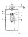
- Fig. 1 shows a device 1 according to the invention, comprising a container 2 in which an amount of beer 3 to be dispensed is included in a first compartment 4.
- the container 2 is a relatively thin-walled can of a relatively large content, for instance 3 or 5 liter.
- the container 2 is closed all round and has its top face provided with a central opening 6 accommodating dispensing means 7, which will be further described hereinbelow.
- Extending under the dispensing means 7 is a pressure control device 8, which will also be further described.
- diverting means 9 Connecting to the dispensing means 7 are diverting means 9 for discharging beer 3, via the dispensing means 7, from the container 2 to, for instance, a glass (not shown).
- a dip tube 10 extends from the dispensing means 7 to a position adjacent the bottom 11 of the container 2, so that the complete volume of beer 3 can be dispensed via the dispensing means 7 and the diverting means 9.
- the dispensing means 7 comprise a passage 12 to which, within the container 2, the dip tube 10 connects and to which, outside the container 2, the diverting means 9 connect.
- the dispensing means 7 further comprise a shut-off valve (not shown) which can be opened against spring pressure and which in a first position seals the dispensing means 7 and in a second position brings the dip tube 10 into fluid communication with the diverting means 9 or at least a duct 13 extending therein.
- a knob 14 is provided, which knob, upon a movement in the direction of the top face 5, moves the shut-off means towards the second position, while by said spring pressure, it is moved in the direction of the first position, for shutting off the device when not actuated.
- Such dispensing means 7 are already known per se and can be adapted or replaced in a known, suitable manner by a skilled person within the framework of the invention.
- the pressure control device 8 comprises a housing 15 having a second compartment 16. Provided adjacent the top end of the housing 15 are pressure control means 17 which will be further described hereinbelow. By suspension means 18, the housing 15 is suspended from the top face 5 or the dispensing means 7, such that a passage opening 19 of the pressure means 17 is positioned at some distance below the dispensing means 7, preferably above the liquid level.
- the pressure control device 8 and the dispensing means 7 are preferably interconnected in such a manner that they can be inserted through the central opening 6 in the top face 5, with the opening 6 being closed by the dispensing means 7 so as to be gastight and liquidtight.
- the pressure control device 8 can readily be placed, while it can moreover also be readily removed, at least in a workshop arranged therefor, for reuse or recycling.
- the filler 20 is designed as an amount of activated carbon fibers having a relatively large internal and external surface area, for adsorbing and/or absorbing therein and thereon a relatively large amount of CO 2 at an acceptable gas pressure within the second compartment 16.
- activated carbon in particular activated carbon fibers having a large specific surface area, preferably between 600 and 1400 m 2 /g and a high internal porosity, in particular more than 55% and preferably between 55 and 80%, is used as filler.
- the fibers preferably have a relatively large external specific surface area, for instance more than 2 dm 3 , more in particular more than 25 dm 3 .
- Such activated carbon fibers are commercially available.
- the use of such filler offers the advantage that the second compartment may be of relatively small design, while sufficient CO 2 can yet be associated.
- a second compartment having a content of about 40 ml may suffice, at a gas pressure in the second compartment of about 10 bar.
- a slightly larger second compartment and the same pressure have been opted for (hence a larger amount of propellant), to obtain a safety margin, so that the container is prevented from not being emptied completely.
- the ratio between the content of the first compartment and the content of the second compartment can for instance be chosen to be > 140:1, for instance 66:1.
- this ratio be greater than 5:1, more preferably greater than 15:1 and most preferably greater than 50:1. Accordingly, for the complete emptying of an above-described container having a content of about 5 l, approximately 18 l CO 2 gas is available, measured at a pressure of 1 bar. It will be directly understood that for any content of a first compartment and the desired excess pressure to be obtained therein, the desired volumes of CO 2 and filler can readily be determined, as well as the desired content of the second compartment, related to pressure and temperature. Further, it will be understood that other fillers can also be used, depending on, inter alia, the application opted for, in particular the propellant to be employed.
- CO 2 acid-treated clay, activated aluminum and bauxite, iron oxide, magnesium oxide, silica gel, and suitable liquids such as acetone and the like can be used.
- acid-treated clay, activated aluminum and bauxite, iron oxide, magnesium oxide, silica gel, and suitable liquids such as acetone and the like can be used.
- CO 2 offers the advantage that, in normal use, it does not have any adverse effect upon the user.
- CO 2 can be obtained relatively easily, for instance as waste product in industrial processes, which reuse is environmentally advantageous.
- the formula P.V./R.T. teaches that thus, at a beer temperature of 7°C in a first compartment of 5 l, about 4.850 1 beer can be maintained under a pressure of about 1.65 bar (0.65 bar excess pressure) and be dispensed therefrom with particularly good drawing properties, while a 100% safety margin is used. At least initially, the CO 2 gas provides a pressure of about 10 bar in the second container.
- the pressure control device 8 is for instance provided with pressure control means 17, which are shown in more detail in Fig. 3 and are known per se from, inter alia, US 5,368,207, which publication with regard to these pressure control means is considered to be incorporated herein by reference.
- pressure control means also known by the name of 'pressure generators', are supplied inter alia by the firm Stabilpress, Belgium.
- the pressure control means 17 comprise a cylindrical casing 20, closed at a first end by a bottom 21 and provided at its other end with a passage opening 19. During use, the passage 19 faces the first compartment 4 and is in open fluid communication therewith.
- a slightly hourglass-shaped piston body 22 Accommodated in the casing 20 is a slightly hourglass-shaped piston body 22, provided at either end with an O-ring or a like seal 23 abutting against the inside of the casing 20. Between the first end 24 of the piston body 22 and the bottom 21, a first chamber 25 is formed, whose size varies according to the axial displacement of the piston body 22 within the casing 20. At the level of the waist 26 of the piston body 22, a number of openings 27 are provided in the casing 20, which are in fluid communication with the second compartment 16.
- a circular groove 28 is included between the openings 27 and the passage 19, on the inside of the casing 20, such that when the O-ring fitted adjacent the second end 29 extends at the level of the groove 28, a slightly limited fluid connection is formed between the second compartment 16, via the openings 27, the space between the O-ring 23 and the groove 28 and the passage 19, to the first compartment 4. Gas of a relatively high pressure can then flow from the second compartment 16 and via this fluid connection into the first compartment 4, whereby the pressure in the first compartment 4 increases.
- a reference pressure is provided which approximately corresponds to the desired pressure in the first compartment 4. If necessary, spring means or the like may be accommodated in the first chamber to effect said reference pressure.
- the piston body 22 is axially displaced in the direction of the bottom 21, such that the reference pressure in the chamber 25 is realized, in which position the O-ring 23 adjacent the second end 29 seals the above-described fluid passage, since the O-ring 23 then abuts against the inside of the casing 20 between the openings 27 and the groove 28.
- a pressure control means as shown in Fig. 3 offers the advantage that it can be manufactured in a relatively simple manner and has an accurate action.
- excess pressure relief means are provided in the first and second compartments, for which purpose, for instance, generally known valves or the like can be employed.
- filtering means 30 are provided in the second compartment 16 for filtering, from the gas flow, particles of the fillers 20, in particular relatively small activated carbon particles, which could have an adverse effect on the quality of the product to be dispensed and, possibly, the health of the user. Moreover, blockages and damages are thus prevented.
- Such filtering means 30 can be constructed in various manners, for instance gauze-shaped, foam-like, textile, semipermeable polymers and the like.
- a device according to Fig. 1 can be employed as follows.
- a suitable amount of beer 3 is introduced into the first compartment 4, via the opening 6.
- the container 1 with the beer can be treated, for instance pasteurized, for which a temporary seal may be inserted into the opening 6, if necessary.
- the pressure control device 8, together with the dip tube 10 and the dispensing means 7, can be inserted into the container 2 via the opening 6, the dispensing means 7 being secured so as to close off the opening 6, for instance through sealing.
- the piston body 22 can be moved away from a sealing position, in which the second end 29 sealingly abuts against the passage 19, for pressurizing the first compartment 1.
- Filling is preferably effected at an excess pressure such that the pressure in the first compartment 1 is at least equal to and preferably higher than the desired operating pressure in the head space of said first compartment 1.
- the diverting means 9 can be placed on the dispensing means 7, whereafter the passage 12 can be released simply by pressing on the knob 14 and the beer 3 is dispensed in a desired amount via the dip tube 10 and the duct 13. Upon release of the knob 14, the passage 12 is closed again as described earlier.
- the pressure control device 8 can be removed again for reuse or separate recycling. Placing the pressure control device can also be done by the user.
- the dispensing means 7 with the diverting means 9, the dip tube 10 and the pressure control device 8 are designed as a unit which can be placed separately.
- a unit can, for instance, be supplied as a loose item and be made of refillable design.
- Fig. 2 shows an alternative embodiment of a device 101 according to the invention, in which the dispensing means 107 and the diverting means 109 are fitted in a sidewall of the container 102.
- the second compartment 116 is fitted in a housing 115, which, at least in normal use, extends entirely above the liquid surface in the first compartment 104.
- the housing 115 through its end 131 opposite the pressure control means 117, represented diagrammatically, is likewise secured to the wall of the container 102.
- a suitable filler for associating the propellant is provided in the second compartment 116.
- a closable feed opening 132 is provided in the wall of container 102, via which propellant can be introduced into the second compartment 116.
- the housing 115 can be designed in any desired manner and can also be arranged at other positions.
- the second compartment 116 may be formed in an upper end, designed as a double-walled lid, of the container 2, 102.
- Fig. 4 shows an alternative embodiment of a device 201 according to the invention, in which the second compartment 216 is provided in a loose housing 215, which can be connected to the first compartment 204 in a container 202 via a first duct 233.
- a pressure control device 208 is included in the first duct 233 for controlling a preferably constant pressure in the container 202.
- the first compartment 204 is connected via a second duct 234 with tapping means 235 with which the passage of the second duct 234, as desired, can be closed or can be released for dispensing beer.
- further first ducts 233 can be connected to the housing 215, so that more containers 202 can be served with gas from the second compartment 216.
- such a cartridge-like housing can be subsequently connected to a number of containers 204 to empty them.
- the fillers 220 here provide the advantage that relatively much gas, in particular CO 2 , can be stored in such a housing, without requiring particularly complex constructional measures and without the safety of the users being thereby affected adversely.
- containers 202 of a relatively large volume for instance 10, 30 or 50 liters, can be emptied with a pressure cartridge 215 of a relatively small volume and limited weight. This further provides logistic advantages.
- Fig. 5 shows a further alternative embodiment of a device according to the invention, in which the first compartment 304 is divided by a flexible membrane 336, for instance a foil-like bag attached to the wall of the container 302, into a chamber 304A for receiving the fluid to be dispensed and a chamber 304B for receiving a volume of propellant which has flowed from the second compartment 316 via the pressure control means 317 described earlier.
- the second compartment 316 is positioned between two bottom walls 311, 311A and, again, is filled with a suitable filler 320.
- Such an embodiment is advantageous in particular when the propellant is to be prevented from coming into direct contact with the fluid to be dispensed in the chamber 304A, since the gas is suitably separated from the fluid by the membrane 336.
- the dispensing means and/or the diverting means can be differently designed, for instance as in known aerosols for obtaining foam. They may also be designed for single-time operation, whereby the entire first compartment is emptied at one time.
- the container 2 can be manufactured in a variety of ways and from different materials, for instance steel, aluminum or plastic. In the exemplary embodiments shown, the containers are of relatively high design, but it will be clear that a variety of dimensions can be utilized, for instance relatively flat, so that such a container can be stored relatively simply in a refrigerator or the like. Further, a variety of additional agents, such as, for instance, cooling agents, may be provided, depending on the application.
- the propellant in normal use, is introduced above the liquid level in the first compartment, which largely prevents a gas stream through the fluid to be dispensed. In particular, premature foaming is thereby prevented.
- a different positioning of the pressure control device can be chosen, such that the propellant is led directly into the fluid to be dispensed.
- an exact appropriate foaming can be obtained, for instance in so-called widgets, soft drinks such as milkshakes and the like.
- the filtering means may additionally, or exclusively, be arranged between the pressure control means 17, 117, 217, 317 and the fluid 3 to be dispensed.
Claims (18)
- Dispositif (1, 101, 201, 301) permettant de distribuer un liquide, comprenant un récipient ayant un premier compartiment (4, 104, 204, 304) et un second compartiment (16, 116, 216, 316), le premier compartiment (4, 104, 204, 304) comprenant un liquide (3) destiné à être distribué, et le second compartiment (16, 116, 216, 316) comprenant un gaz propulseur, alors qu'au moins pendant l'utilisation, une ouverture (19) est prévue entre le premier (4, 104, 204, 304) et le second compartiment (16, 116, 216, 316), des moyens de régulation de pression (8, 17, 117, 217, 317) qui sont agencés pour réguler pendant l'utilisation, la pression du gaz propulseur qui s'écoule du second compartiment (16, 116, 216, 316) dans le premier compartiment (4, 104, 204, 304), alors que dans le second compartiment (16, 116, 216, 316) on prévoit des charges (20) pour absorber et/ou adsorber au moins une partie du gaz propulseur, caractérisé en ce que ledit liquide (3) est une boisson gazeuse et que le gaz propulseur contient au moins du dioxyde de carbone (CO2), alors que les charges (20) comprennent au moins du charbon actif dans lequel les moyens de régulation de pression (8, 17, 117, 217, 317) sont agencés de sorte que pendant l'utilisation, une situation d'équilibre soit maintenue dans une chambre de pression du premier compartiment.
- Dispositif selon la revendication 1, dans lequel le gaz propulseur est du CO2 relativement pur et les charges (20) sont formées au moins sensiblement avec des fibres de charbon actif.
- Dispositif selon l'une quelconque des revendications précédentes, dans lequel les moyens de régulation de pression (8, 17, 117, 217, 317) sont réglés pour fournir et maintenir dans le premier compartiment (4, 104, 204, 304) une surpression entre 0,1 et 2 bar, et plus particulièrement entre 0,2 et 1 bar et de préférence d'environ 0,7 bar par rapport au milieu.
- Dispositif selon l'une quelconque des revendications précédentes, dans lequel on prévoit, par litre de boisson gazeuse (3), entre 2 et 20 grammes, en particulier entre 6 et 18 grammes de charbon actif.
- Dispositif selon l'une quelconque des revendications précédentes, dans lequel, par litre de boisson gazeuse, entre 1 et 10 grammes, en particulier entre 2 et 8 grammes de CO2 sont compris, associés aux charges (20).
- Dispositif selon l'une quelconque des revendications précédentes, dans lequel le rapport entre le volume du premier compartiment (4, 104, 204, 304) et du second compartiment (16, 116, 216, 316) est supérieur à 5, 5/1, plus particulièrement supérieur à 15/1, de préférence supérieur à 50/1.
- Dispositif selon l'une quelconque des revendications précédentes, dans lequel la pression dans le second compartiment (16, 116, 216, 316), au moins avant l'utilisation, est entre 4 et 16 bar, plus particulièrement entre 5 et 12 bar, et de préférence environ 10 bar, mesurée à la température d'application.
- Dispositif selon l'une quelconque des revendications précédentes, dans lequel le premier (4, 104, 204, 304) et/ou le second compartiment (16, 116, 216, 316) sont prévus avec des moyens de décharge de surpression pour laisser s'échapper d'une manière contrôlée, à une pression supérieure à une pression maximum présélectionnée, au moins une partie du liquide sous pression, alors que de préférence une pression maximum inférieure à 16 bar, en particulier inférieure à 12 bar, dans le second compartiment (16, 116, 216, 316) est déterminée.
- Dispositif selon l'une quelconque des revendications précédentes, dans lequel les moyens de régulation de pression (8, 17, 117, 217, 317) comprennent une valve d'autorégulation.
- Dispositif selon l'une quelconque des revendications précédentes, dans lequel le premier (4, 104, 204, 304) et le second compartiment (16, 116, 216, 316) sont incorporés de manière fixe dans le récipient, alors que l'on prévoit des moyens pour remplir le second compartiment (16, 116, 216, 316) avec le gaz propulseur depuis l'extérieur du récipient, avant l'usage.
- Dispositif selon l'une quelconque des revendications 1 à 9, dans lequel le second compartiment (16, 116, 216, 316) est conçu comme un récipient, de préférence en forme de cartouche, comprenant au moins une partie des moyens de régulation de pression (8, 17, 117, 217, 317), alors que l'on prévoit des moyens pour coupler le second compartiment (16, 116, 216, 316) avec le premier compartiment (4, 104, 204, 304) avant l'utilisation.
- Dispositif selon l'une quelconque des revendications précédentes, dans lequel un tube plongeur (10) est fixé au second compartiment (16, 116, 216, 316), lequel tube plongeur (10) a une première extrémité se terminant de manière adjacente au fond du premier compartiment (4, 104, 204, 304) et via sa seconde extrémité opposée, peut être amené en communication de fluide avec des moyens de distribution (7 ; 107, 307 ; 234, 235) prévus pour le liquide à distribuer.
- Ensemble composé d'un second compartiment, d'un tube plongeur (10) et de moyens de distribution (7 ; 107, 307 ; 234, 235) tels que définis dans un dispositif selon l'une quelconque des revendications précédentes, en particulier pour un dispositif selon la revendication 12.
- Procédé permettant de garder une boisson gazeuse sous pression et de distribuer ladite boisson, dans lequel la boisson est contenue dans un récipient (2, 102, 202, 302), dans lequel un gaz propulseur est stocké sous une pression relativement élevée dans un compartiment (4, 104, 204, 304), dans lequel le compartiment est amené en communication avec le récipient (2, 102, 202, 302), de sorte qu'à l'aide du gaz propulseur, la boisson est mise sous pression et ainsi maintenue et peut être distribuée via des moyens de distribution (7 ; 107, 307 ; 234, 235), dans lequel avant l'introduction du gaz propulseur dans le compartiment (16, 116, 216, 316), une charge (20) comprenant du charbon actif est introduite dans le compartiment, laquelle charge (20) peut absorber et/ou adsorber au moins une partie du gaz propulseur, de sorte qu'une certaine quantité du gaz propulseur est introduite dans le compartiment (16, 116, 216, 316) à une pression qui est considérablement inférieure à la pression qui se produit dans le même compartiment (16, 116, 216, 316) avec la même quantité de gaz propulseur et dans les mêmes conditions externes si la charge n'est pas contenue à l'intérieur, caractérisé en ce que le gaz propulseur est introduit dans le compartiment (16, 116, 216, 316) sous une pression comprise entre 4 et 14 bar, plus particulièrement entre 5 et 12 bar, et de préférence environ 10 bar, mesurée à la température d'application, tout en utilisant les moyens de régulation de pression (8, 17, 117, 217, 317), le gaz propulseur, lorsque la boisson (3) est distribuée via les moyens de distribution (7 ; 107, 307 ; 234, 235), est distribué à une certaine pression de sorte que dans le récipient, on maintient une surpression afin de maintenir pendant l'utilisation, une situation d'équilibre dans une chambre de pression du récipient (2, 102, 202, 32).
- Procédé selon la revendication 14, dans lequel une surpression est maintenue entre 0,1 et 1,5 bar, plus particulièrement 0,2 et 1 bar, et de préférence environ 0,7 bar par rapport au milieu.
- Cartouche sous pression destinée à être utilisée dans un dispositif selon l'une quelconque des revendications 1 à 13 ou un procédé selon la revendication 14 ou 15, comprenant une charge (20) comprenant du charbon actif, en particulier des fibres de charbon actif, capable d'adsorber et/ou d'absorber un gaz propulseur, en particulier du dioxyde de carbone pur, et comprenant des moyens de raccordement pour amener la cartouche sous pression en communication de fluide avec un compartiment (4, 104, 204, 304) dans un récipient, pour faire passer au moins une partie du gaz propulseur dans une boisson présente dans le récipient (2, 102, 202, 302).
- Cartouche sous pression selon la revendication 16, dans laquelle les moyens de régulation de pression (8, 17, 117, 217, 317) sont prévus pour maintenir, pendant l'utilisation, une surpression relativement constante dans un récipient raccordé à la cartouche sous pression.
- Utilisation d'une cartouche sous pression selon la revendication 16 ou 17 pour distribuer une boisson gazeuse, en particulier de la bière.
Priority Applications (1)
| Application Number | Priority Date | Filing Date | Title |
|---|---|---|---|
| SI9930880T SI1170247T1 (sl) | 1998-03-16 | 1999-03-16 | Priprava za oddajanje tekocine pod tlakom |
Applications Claiming Priority (3)
| Application Number | Priority Date | Filing Date | Title |
|---|---|---|---|
| NL1008601 | 1998-03-16 | ||
| NL1008601A NL1008601C2 (nl) | 1998-03-16 | 1998-03-16 | Inrichting voor het afgeven van een fluïdum. |
| EP99910867A EP1064221B1 (fr) | 1998-03-16 | 1999-03-16 | Dispositif de distribution d'un liquide sous pression |
Related Parent Applications (2)
| Application Number | Title | Priority Date | Filing Date |
|---|---|---|---|
| EP99910867A Division EP1064221B1 (fr) | 1998-03-16 | 1999-03-16 | Dispositif de distribution d'un liquide sous pression |
| EP99910867A Division-Into EP1064221B1 (fr) | 1998-03-16 | 1999-03-16 | Dispositif de distribution d'un liquide sous pression |
Publications (2)
| Publication Number | Publication Date |
|---|---|
| EP1170247A1 EP1170247A1 (fr) | 2002-01-09 |
| EP1170247B1 true EP1170247B1 (fr) | 2005-12-07 |
Family
ID=19766748
Family Applications (2)
| Application Number | Title | Priority Date | Filing Date |
|---|---|---|---|
| EP99910867A Expired - Lifetime EP1064221B1 (fr) | 1998-03-16 | 1999-03-16 | Dispositif de distribution d'un liquide sous pression |
| EP01202598A Expired - Lifetime EP1170247B1 (fr) | 1998-03-16 | 1999-03-16 | Dispositif de distribution de liquide sous pression |
Family Applications Before (1)
| Application Number | Title | Priority Date | Filing Date |
|---|---|---|---|
| EP99910867A Expired - Lifetime EP1064221B1 (fr) | 1998-03-16 | 1999-03-16 | Dispositif de distribution d'un liquide sous pression |
Country Status (43)
Families Citing this family (94)
| Publication number | Priority date | Publication date | Assignee | Title |
|---|---|---|---|---|
| EP1140692B1 (fr) * | 1998-12-16 | 2002-11-27 | Heineken Technical Services B.V. | Recipient prevu pour stocker et distribuer de la boisson, plus particulierement de la biere |
| WO2001032550A1 (fr) * | 1999-11-03 | 2001-05-10 | Anders Blicher | Appareil de distribution de boissons |
| RU2171765C1 (ru) * | 2000-02-29 | 2001-08-10 | Центр КОРТЭС | Капсула для хранения газа и способ ее заправки |
| WO2002014210A1 (fr) * | 2000-08-16 | 2002-02-21 | Lim Walter K | Systeme de stockage et de distribution de gaz pour recipients sous pression |
| RU2228892C2 (ru) * | 2002-05-08 | 2004-05-20 | Центр КОРТЭС | Распыляющий контейнер |
| FR2843950B1 (fr) * | 2002-08-30 | 2004-11-19 | Oreal | Valve pour recipient pressurise et recipient ainsi equipe |
| US6776313B2 (en) | 2002-08-30 | 2004-08-17 | L'oreal | Valve for a pressurized receptacle, and a receptacle fitted therewith |
| US20050048428A1 (en) * | 2003-08-25 | 2005-03-03 | Lim Walter K. | Device and method for extinguishing a candle flame |
| EP2327921B1 (fr) * | 2003-12-03 | 2021-06-09 | Chemviron Carbon Limited | Procédé de chargement de CO2 sur du charbon actif dans un distributeur de fluide |
| EP1706335B1 (fr) * | 2004-01-23 | 2011-03-16 | Kbig Limited | Systeme de distribution de produits et methode pour sa fabrication |
| US7185786B2 (en) * | 2004-06-12 | 2007-03-06 | Krause Arthur A | Gas storage and delivery system for pressurized containers |
| US8746503B2 (en) * | 2004-06-12 | 2014-06-10 | Walter K. Lim | System and method for providing a reserve supply of gas in a pressurized container |
| NL1027998C2 (nl) * | 2005-01-11 | 2006-07-12 | Heineken Tech Services | Drukregelinrichting voor een container en container voorzien van een dergelijke drukregelinrichting. |
| US7861740B2 (en) * | 2005-12-15 | 2011-01-04 | Niagara Dispensing Technologies, Inc. | Digital flow control |
| US20070193653A1 (en) * | 2005-12-15 | 2007-08-23 | Thomas Gagliano | Beverage dispenser |
| AU2006330641A1 (en) | 2005-12-15 | 2007-07-05 | Niagara Dispensing Technologies, Inc. | Beverage dispensing |
| NL1031411C2 (nl) * | 2006-03-20 | 2007-09-21 | Heineken Supply Chain Bv | Tapinrichting. |
| NL1031410C2 (nl) * | 2006-03-20 | 2007-09-21 | Heineken Supply Chain Bv | Drankcontainer en samenstel van een dergelijke container en een tapinrichting. |
| NL1031412C2 (nl) | 2006-03-20 | 2007-09-21 | Heineken Supply Chain Bv | Container voor drank. |
| GB0621881D0 (en) * | 2006-11-02 | 2006-12-13 | Kbig Ltd | Product dispensing sytems |
| NL1032893C2 (nl) * | 2006-11-17 | 2008-05-20 | Heineken Supply Chain Bv | Container voor het afgeven van drank. |
| US20080142115A1 (en) * | 2006-12-15 | 2008-06-19 | Niagara Dispensing Technologies, Inc. | Beverage dispensing |
| US7823411B2 (en) | 2006-12-15 | 2010-11-02 | Niagara Dispensing Technologies, Inc. | Beverage cooling system |
| WO2008105001A1 (fr) * | 2007-02-26 | 2008-09-04 | Mauro De Mei | Système de conditionnement hermétique d'un liquide de consommation à l'intérieur d'un récipient, en vue de sa préservation contre la contamination et la détérioration au stade de l'entreposage ainsi qu'à celui de l'introduction et/ou de la distribution |
| US20080202148A1 (en) * | 2007-02-27 | 2008-08-28 | Thomas Gagliano | Beverage cooler |
| US20090302038A1 (en) * | 2007-03-09 | 2009-12-10 | Taggart Jeffrey S | Beverage Dispensing Assembly |
| US8070023B2 (en) * | 2007-03-09 | 2011-12-06 | On Tap Llc | Beverage dispensing assembly |
| US20080217363A1 (en) * | 2007-03-09 | 2008-09-11 | Vitantonio Marc L | Beverage dispensing assembly |
| US20080217362A1 (en) * | 2007-03-09 | 2008-09-11 | On Tap Llc | Beverage dispensing assembly |
| US20090321443A1 (en) * | 2007-03-09 | 2009-12-31 | Taggart Jeffrey S | Method for filling a vessel with a gas entrained beverage and a consumable consumer product including the beverage |
| US20090140006A1 (en) * | 2007-03-09 | 2009-06-04 | Vitantonio Marc L | Beverage dispensing assembly |
| CN101348228B (zh) * | 2007-07-18 | 2012-01-25 | 黄义忠 | 液体汲取器 |
| US20090108032A1 (en) * | 2007-10-26 | 2009-04-30 | Heineken Supply Chain B.V. | System, Method and Network for Distributing Beverages |
| DE102007054659A1 (de) * | 2007-11-14 | 2009-05-20 | SCHäFER WERKE GMBH | Verfahren zum Entnehmen von Flüssigkeit aus einem Getränkebehälter und Getränkebehälter |
| NL1035235C2 (nl) | 2008-03-31 | 2009-10-01 | Heineken Supply Chain Bv | Tapinrichting, voorzien van een drukregelinrichting. |
| NL1035233C2 (nl) | 2008-03-31 | 2009-10-01 | Heineken Supply Chain Bv | Drukregelaar en tapinrichting voorzien daarvan. |
| NL2001467C2 (nl) * | 2008-04-10 | 2009-10-13 | Heineken Supply Chain Bv | Inrichting voor houden van drank. |
| US8066156B2 (en) * | 2008-05-21 | 2011-11-29 | Millercoors Llc | Beverage dispensing device |
| US20090308898A1 (en) * | 2008-06-12 | 2009-12-17 | Jason Polano | Beer ball |
| NL2001882C2 (nl) | 2008-08-12 | 2010-02-15 | Heineken Supply Chain Bv | Tapkop, tapinrichting en werkwijze voor gebruik van een tapinrichting. |
| EP2184259A1 (fr) | 2008-11-05 | 2010-05-12 | Carlsberg Breweries A/S | Dispositif de génération de pression pour système de distribution de boissons |
| DE102009015427A1 (de) | 2009-03-27 | 2010-10-07 | Schreiner, Udo | Verwendung eines Behälters |
| EP2241531A1 (fr) | 2009-04-15 | 2010-10-20 | Carlsberg Breweries A/S | Procédé et système pour pressuriser et distribuer des boissons carbonatées |
| EP2419369A1 (fr) * | 2009-04-15 | 2012-02-22 | Carlsberg Breweries A/S | Procédé et système pour la mise sous pression et la distribution de boissons gazeuses |
| NZ603507A (en) * | 2010-05-19 | 2013-06-28 | Joseph Co Int Inc | Keg with heat exchange unit including segments of compressed carbon |
| NL2006199C2 (en) * | 2011-02-14 | 2012-08-15 | Heineken Supply Chain Bv | Method and apparatus for dispensing beverages, especially carbonated beverages. |
| NL2006197C2 (en) * | 2011-02-14 | 2012-08-15 | Heineken Supply Chain Bv | Method and apparatus for dispensing beverages, especially carbonated beverages. |
| US20130233895A1 (en) | 2010-06-02 | 2013-09-12 | Heineken Supply Chain B.V. | Method and apparatus for dispensing beverages, especially carbonated beverages |
| HUP1000286A2 (en) | 2010-06-02 | 2011-12-28 | Mayex Canada Kft | Dispensing unit and method for dispensing a liquid under pressure |
| KR101142574B1 (ko) * | 2010-06-11 | 2012-05-11 | 이광무 | 배출량 제어가 가능한 액체용기 |
| CN103068718B (zh) * | 2010-06-17 | 2015-04-15 | 嘉士伯酿酒有限公司 | 吸收啤酒配给系统的推进剂气体的方法 |
| EP2444365A1 (fr) | 2010-10-20 | 2012-04-25 | Carlsberg Breweries A/S | Procédé de remplissage d'un dispositif de génération de pression |
| HUP1000346A2 (en) | 2010-06-30 | 2012-03-28 | Mayex Canada Kft | Gas cartridge for liquid dispensing devices |
| NL2006195C2 (en) * | 2011-02-14 | 2012-08-15 | Heineken Supply Chain Bv | Method and apparatus for packaging beverage under pressure. |
| MX2013009376A (es) * | 2011-02-14 | 2014-03-27 | Heineken Supply Chain Bv | Metodo y aparato para el envasado de bebidas bajo presion. |
| EP2514711A1 (fr) | 2011-04-18 | 2012-10-24 | Anheuser-Busch InBev S.A. | Appareil de distribution de liquide comportant une adsorption de gaz solide |
| AU2012290003A1 (en) * | 2011-08-03 | 2014-02-27 | Keurig Green Mountain, Inc. | Method and apparatus for cartridge-based carbonation of beverages |
| EP2626317A1 (fr) * | 2012-02-13 | 2013-08-14 | de Schrijver, Aster | Systèmes d'emballage sous pression pour des adhésifs mono-composants et produits d'étanchéité |
| US8851331B2 (en) * | 2012-05-04 | 2014-10-07 | Ecolab Usa Inc. | Fluid dispensers with adjustable dosing |
| NL2009235C2 (en) | 2012-07-26 | 2014-01-28 | Heineken Supply Chain Bv | Container and set of preforms for forming a container. |
| NL2009237C2 (en) | 2012-07-26 | 2014-01-28 | Heineken Supply Chain Bv | Connecting device and tapping assembly as well as a container and method for beverage dispensing. |
| NL2009236C2 (en) | 2012-07-26 | 2014-02-06 | Heineken Supply Chain Bv | Container and set of preforms for forming a container. |
| NL2009234C2 (en) | 2012-07-26 | 2014-02-06 | Heineken Supply Chain Bv | Tapping assembly and connecting device, as well as a container and method for beverage dispensing. |
| NL2009863C2 (en) | 2012-11-22 | 2014-05-27 | Heineken Supply Chain Bv | Beverage dispensing assembly and valve operating assembly therefore. |
| NL2009864C2 (en) | 2012-11-22 | 2014-05-27 | Heineken Supply Chain Bv | Beverage dispensing assembly and container for use in a beverage dispensing assembly. |
| JP6094860B2 (ja) * | 2012-12-05 | 2017-03-15 | 紀伊産業株式会社 | ピッチャー |
| EP2786960A1 (fr) | 2013-04-05 | 2014-10-08 | Carlsberg Breweries A/S | Piège provoquant un flux constant de la bière |
| EP2803631A1 (fr) * | 2013-05-16 | 2014-11-19 | Carlsberg Breweries A/S | Système et procédé de distribution de boisson |
| WO2014184314A1 (fr) | 2013-05-17 | 2014-11-20 | Carlsberg Breweries A/S | Procédé de fabrication d'un système de distribution de boisson comprenant une alimentation en gaz |
| EP3003960B1 (fr) * | 2013-06-04 | 2020-02-12 | The Coca-Cola Company | Cartouches de préparation de boissons destinées à être utilisées dans une machine de préparation de boissons |
| EP2923998A1 (fr) | 2014-03-24 | 2015-09-30 | Anheuser-Busch InBev S.A. | Connecteur KEG intégrale |
| AU2015267256A1 (en) * | 2014-05-24 | 2016-12-15 | GrowlerWerks, INC. | Beverage dispenser and variable presure regulator cap assembly |
| NL2012981B1 (en) | 2014-06-11 | 2017-01-17 | Heineken Supply Chain Bv | Beverage dispensing system, beverage container and pressurizing system for use in a beverage dispensing system or container. |
| RS54809B1 (sr) | 2014-07-30 | 2016-10-31 | Miloš Milošević | Uređaj za istakanje i raspodelu napitka iz flaše |
| EP2987767A1 (fr) | 2014-08-19 | 2016-02-24 | Anheuser-Busch InBev S.A. | Appareil de distribution de boisson pour récipients multiples |
| EP3048345A1 (fr) | 2015-01-21 | 2016-07-27 | Anheuser-Busch InBev S.A. | Robinet pour distributeur de boissons |
| US10207232B2 (en) * | 2015-06-18 | 2019-02-19 | Hiroaki Minakawa | Dissolved hydrogen liquid-discharging pot and method for generating pressurized dissolved hydrogen liquid |
| NL2017109B1 (en) | 2016-07-05 | 2018-01-12 | Heineken Supply Chain Bv | Beverage dispensing assembly and beverage container |
| EP3284713A1 (fr) * | 2016-08-20 | 2018-02-21 | Ardagh MP Group Netherlands B.V. | Fut comprenant un clapet de refoulement pour la conservation de bière et procédé de réglage de la pression dans ledit fut |
| BR112019003230A2 (pt) * | 2016-08-20 | 2019-06-18 | Ardagh Mp Group Netherlands Bv | recipiente para armazenar líquido, válvula de pres-são para tal finalidade e uso do recipiente como barril de cerveja; método para regular a pressão em um tal recipiente; base oca para recipiente, sis-tema modular para fabricação de uma base oca pa-ra recipiente e método para preenchimento de um recipiente |
| EP3562776A1 (fr) | 2016-12-27 | 2019-11-06 | Midnight Madness Distilling, LLC | Distributeur de liquide effervescent |
| JP2020505277A (ja) | 2017-01-20 | 2020-02-20 | アルダフ エムピー グループ ネザーランド ベー.ヴェー. | 腐食作用を及ぼす液体を保存する容器、その容器の使用方法、およびその容器に腐食作用を及ぼす液体を充填する方法 |
| DE102017101149B3 (de) | 2017-01-20 | 2018-04-26 | Ardagh Mp Group Netherlands B.V. | Behälter zum Aufbewahren einer korrosiv wirkenden Flüssigkeit, Verwendungen und Verfahren zur Befüllung |
| CN110392665B (zh) | 2017-03-10 | 2022-10-21 | 约瑟夫国际股份有限公司 | 压力调节阀 |
| NL2018955B1 (en) | 2017-05-19 | 2018-11-28 | Heineken Supply Chain Bv | Beverage dispensing assembly and beverage container |
| NL2018956B1 (en) | 2017-05-19 | 2018-11-28 | Heineken Supply Chain Bv | Beverage dispensing assembly and beverage container |
| WO2019023059A1 (fr) | 2017-07-25 | 2019-01-31 | Midnight Madness Distilling, Llc | Distributeur de liquide effervescent |
| WO2019159131A1 (fr) | 2018-02-19 | 2019-08-22 | Ardagh Mp Group Netherlands B.V. | Récipient avec une vanne de régulation pour la pression dans le récipient, procédé de régulation de la pression, récipient métallique |
| NL2020756B1 (en) | 2018-04-12 | 2019-10-23 | Heineken Supply Chain Bv | Pressure regulating system for a beverage container and beverage container provided therewith |
| GB2578883B (en) | 2018-11-09 | 2022-07-13 | Polykeg S R L | Bag-in-keg container with fixed pressure PRV |
| WO2020246884A1 (fr) | 2019-06-04 | 2020-12-10 | Heineken Supply Chain B.V. | Dispositif de commande de pression pour un récipient de boisson |
| NL2023563B1 (en) | 2019-07-24 | 2021-02-10 | Heineken Supply Chain Bv | Pressure regulating system for a beverage container and beverage container provided therewith |
| US20230016747A1 (en) * | 2021-07-15 | 2023-01-19 | Podsy Partners, Llc | Cleaning Kit with Reusable Applicator and Compact Structure |
| WO2023034462A1 (fr) * | 2021-08-31 | 2023-03-09 | Versabev, Inc. | Système modulaire évolutif et procédé de commande de robinet et de distribution sélective de boissons |
Family Cites Families (20)
| Publication number | Priority date | Publication date | Assignee | Title |
|---|---|---|---|---|
| US4049158A (en) * | 1975-11-13 | 1977-09-20 | S. C. Johnson & Son, Inc. | Pressurized container-dispensers and filling method |
| JPS53132805A (en) * | 1977-04-25 | 1978-11-20 | Kamaya Kagaku Kogyo Co Ltd | Aerosol type atomizer |
| FR2411798A1 (fr) * | 1977-12-19 | 1979-07-13 | Waterlomat Sa | Appareil de soutirage de boissons carbonatees contenues dans des recipients a reserve de gaz incorporee |
| CH618896A5 (fr) * | 1979-01-22 | 1980-08-29 | Paul Comment | |
| JPS61201997A (ja) * | 1985-03-01 | 1986-09-06 | Kashiwa Kagaku Kogyo:Kk | 圧縮ガスの充填方法 |
| GB8507352D0 (en) * | 1985-03-21 | 1985-05-01 | Porter Lancastrian Ltd | Dispensing of beverages |
| JPS62271873A (ja) * | 1986-05-10 | 1987-11-26 | 三菱商事株式会社 | 注出装置 |
| DE3878134T2 (de) * | 1987-10-15 | 1993-08-26 | Coca Cola Co | Apparatur zum chemischen erzengung und entnahme von gasen. |
| JPH0332493U (fr) * | 1989-08-04 | 1991-03-29 | ||
| BE1003682A3 (nl) * | 1990-02-09 | 1992-05-19 | Jaico Cv | Drukkapsule voor spuitbus en spuitbus die zulke drukkapsule toepast. |
| US5011047A (en) * | 1990-09-05 | 1991-04-30 | I.P.R.S. | Dispensing apparatus |
| FR2690142B1 (fr) * | 1992-04-17 | 1995-11-17 | Oreal | Recipient pressurise, en particulier boitier aerosol, pour la distribution sous pression d'un composant liquide ou pateux. |
| ATE191201T1 (de) | 1992-04-30 | 2000-04-15 | I P R S U S A | Abgabevorrichtung mit einem druckerzeuger |
| US5234140A (en) * | 1992-07-28 | 1993-08-10 | S. C. Johnson & Son, Inc. | Re-useable aerosol container |
| WO1995017340A1 (fr) * | 1993-12-22 | 1995-06-29 | Acma Limited | Appareil et procede de liberation de gaz sorbes |
| RU2105709C1 (ru) * | 1994-02-14 | 1998-02-27 | Центр комплексного развития технологии и энерготехнологических систем "Кортэс" | Способ создания избыточного давления в пропеллентной системе и устройство для его осуществления |
| RU2086489C1 (ru) * | 1994-02-14 | 1997-08-10 | Центр комплексного развития технологии и энерготехнологических систем "Кортэс" | Капсула для упаковки, аэрозольная упаковка, самоохлаждаемая упаковка (варианты), способ создания давления в аэрозольной упаковке и способ охлаждения жидкости |
| JP2804903B2 (ja) * | 1995-02-24 | 1998-09-30 | 麒麟麦酒株式会社 | 卓上型ディスペンサ |
| JP2987686B2 (ja) * | 1996-01-31 | 1999-12-06 | 東京瓦斯株式会社 | ガスの貯蔵方法 |
| JPH1066865A (ja) * | 1996-08-28 | 1998-03-10 | Osaka Gas Co Ltd | 難燃性ガス貯蔵剤、難燃性ガス貯蔵方法ならびに高圧難燃性ガス発生装置 |
-
1998
- 1998-03-16 NL NL1008601A patent/NL1008601C2/nl not_active IP Right Cessation
-
1999
- 1999-03-15 OA OA1200000244A patent/OA11688A/en unknown
- 1999-03-15 MA MA25494A patent/MA25587A1/fr unknown
- 1999-03-16 EP EP99910867A patent/EP1064221B1/fr not_active Expired - Lifetime
- 1999-03-16 AP APAP/P/2000/001897A patent/AP1273A/en active
- 1999-03-16 EA EA200000943A patent/EA002334B1/ru not_active IP Right Cessation
- 1999-03-16 EP EP01202598A patent/EP1170247B1/fr not_active Expired - Lifetime
- 1999-03-16 SI SI9930055T patent/SI1064221T1/xx unknown
- 1999-03-16 IL IL13833399A patent/IL138333A/en not_active IP Right Cessation
- 1999-03-16 CA CA002323669A patent/CA2323669C/fr not_active Expired - Fee Related
- 1999-03-16 JP JP2000536650A patent/JP5628465B2/ja not_active Expired - Lifetime
- 1999-03-16 PT PT99910867T patent/PT1064221E/pt unknown
- 1999-03-16 RS YUP-564/00A patent/RS49804B/sr unknown
- 1999-03-16 SV SV1999000025A patent/SV1999000025A/es not_active Application Discontinuation
- 1999-03-16 DK DK99910867T patent/DK1064221T3/da active
- 1999-03-16 AT AT01202598T patent/ATE312052T1/de active
- 1999-03-16 UY UY25434A patent/UY25434A1/es not_active Application Discontinuation
- 1999-03-16 BR BR9908840-1A patent/BR9908840A/pt not_active IP Right Cessation
- 1999-03-16 US US09/623,732 patent/US6360923B1/en not_active Expired - Lifetime
- 1999-03-16 SI SI9930880T patent/SI1170247T1/sl unknown
- 1999-03-16 HU HU0103367A patent/HU225173B1/hu not_active IP Right Cessation
- 1999-03-16 NZ NZ506696A patent/NZ506696A/en not_active IP Right Cessation
- 1999-03-16 NL NL1011570A patent/NL1011570C2/nl not_active IP Right Cessation
- 1999-03-16 SK SK1384-2000A patent/SK287164B6/sk not_active IP Right Cessation
- 1999-03-16 AT AT99910867T patent/ATE213717T1/de active
- 1999-03-16 WO PCT/NL1999/000144 patent/WO1999047451A1/fr active Application Filing
- 1999-03-16 ES ES99910867T patent/ES2173728T3/es not_active Expired - Lifetime
- 1999-03-16 AU AU29631/99A patent/AU753638B2/en not_active Expired
- 1999-03-16 TR TR2000/02659T patent/TR200002659T2/xx unknown
- 1999-03-16 AR ARP990101136A patent/AR017474A1/es active IP Right Grant
- 1999-03-16 GE GEAP19995594A patent/GEP20043235B/en unknown
- 1999-03-16 PE PE1999000218A patent/PE20000299A1/es not_active Application Discontinuation
- 1999-03-16 CZ CZ20003335A patent/CZ302977B6/cs not_active IP Right Cessation
- 1999-03-16 DE DE69900940T patent/DE69900940T2/de not_active Expired - Lifetime
- 1999-03-16 MY MYPI99000971A patent/MY122435A/en unknown
- 1999-03-16 KR KR1020007010212A patent/KR100545104B1/ko not_active IP Right Cessation
- 1999-03-16 ID IDW20002071A patent/ID27453A/id unknown
- 1999-03-16 EE EEP200000534A patent/EE04365B1/xx not_active IP Right Cessation
- 1999-03-16 CN CNB99804119XA patent/CN1165483C/zh not_active Expired - Lifetime
- 1999-03-16 PL PL99342939A patent/PL190592B1/pl unknown
- 1999-03-16 DE DE69928837T patent/DE69928837T2/de not_active Expired - Lifetime
- 1999-03-16 ES ES01202598T patent/ES2253322T3/es not_active Expired - Lifetime
- 1999-03-16 DK DK01202598T patent/DK1170247T3/da active
- 1999-10-05 GT GT199900170A patent/GT199900170A/es unknown
-
2000
- 2000-08-31 ZA ZA200004541A patent/ZA200004541B/en unknown
- 2000-09-14 BG BG104765A patent/BG64045B1/bg unknown
- 2000-09-15 HR HR20000607A patent/HRP20000607B1/xx not_active IP Right Cessation
- 2000-09-15 NO NO20004630A patent/NO318334B1/no not_active IP Right Cessation
- 2000-09-15 CU CU20000203A patent/CU22987A3/es unknown
-
2001
- 2001-04-04 HK HK01102427A patent/HK1033449A1/xx not_active IP Right Cessation
-
2009
- 2009-04-14 HR HR20090223A patent/HRP20090223A2/xx not_active Application Discontinuation
Also Published As
Similar Documents
| Publication | Publication Date | Title |
|---|---|---|
| EP1170247B1 (fr) | Dispositif de distribution de liquide sous pression | |
| US8469239B2 (en) | Pressure control device for a container | |
| AU765332B2 (en) | Container for storing and dispensing beverage, in particular beer | |
| US4264019A (en) | Beverage dispenser | |
| MXPA00009082A (en) | Device for dispensing a liquid under pressure | |
| NZ556414A (en) | Pressure control device for a container |
Legal Events
| Date | Code | Title | Description |
|---|---|---|---|
| PUAI | Public reference made under article 153(3) epc to a published international application that has entered the european phase |
Free format text: ORIGINAL CODE: 0009012 |
|
| AC | Divisional application: reference to earlier application |
Ref document number: 1064221 Country of ref document: EP |
|
| AK | Designated contracting states |
Kind code of ref document: A1 Designated state(s): AT BE CH CY DE DK ES FI FR GB GR IE IT LI LU MC NL PT SE |
|
| AX | Request for extension of the european patent |
Free format text: AL PAYMENT 20010705;LT PAYMENT 20010705;LV PAYMENT 20010705;MK PAYMENT 20010705;RO PAYMENT 20010705;SI PAYMENT 20010705 |
|
| 17P | Request for examination filed |
Effective date: 20010705 |
|
| AKX | Designation fees paid |
Free format text: AT BE CH CY DE DK ES FI FR GB GR IE IT LI LU MC NL PT SE |
|
| AXX | Extension fees paid |
Free format text: AL PAYMENT 20010705;LT PAYMENT 20010705;LV PAYMENT 20010705;MK PAYMENT 20010705;RO PAYMENT 20010705;SI PAYMENT 20010705 |
|
| 17Q | First examination report despatched |
Effective date: 20021129 |
|
| GRAP | Despatch of communication of intention to grant a patent |
Free format text: ORIGINAL CODE: EPIDOSNIGR1 |
|
| GRAS | Grant fee paid |
Free format text: ORIGINAL CODE: EPIDOSNIGR3 |
|
| GRAA | (expected) grant |
Free format text: ORIGINAL CODE: 0009210 |
|
| AC | Divisional application: reference to earlier application |
Ref document number: 1064221 Country of ref document: EP Kind code of ref document: P |
|
| AK | Designated contracting states |
Kind code of ref document: B1 Designated state(s): AT BE CH CY DE DK ES FI FR GB GR IE IT LI LU MC NL PT SE |
|
| AX | Request for extension of the european patent |
Extension state: AL LT LV MK RO SI |
|
| REG | Reference to a national code |
Ref country code: GB Ref legal event code: FG4D |
|
| REG | Reference to a national code |
Ref country code: CH Ref legal event code: EP |
|
| REG | Reference to a national code |
Ref country code: IE Ref legal event code: FG4D |
|
| REF | Corresponds to: |
Ref document number: 69928837 Country of ref document: DE Date of ref document: 20060112 Kind code of ref document: P |
|
| REG | Reference to a national code |
Ref country code: SE Ref legal event code: TRGR |
|
| PG25 | Lapsed in a contracting state [announced via postgrant information from national office to epo] |
Ref country code: LU Free format text: LAPSE BECAUSE OF NON-PAYMENT OF DUE FEES Effective date: 20060331 Ref country code: MC Free format text: LAPSE BECAUSE OF NON-PAYMENT OF DUE FEES Effective date: 20060331 |
|
| REG | Reference to a national code |
Ref country code: CH Ref legal event code: NV Representative=s name: R. A. EGLI & CO. PATENTANWAELTE |
|
| REG | Reference to a national code |
Ref country code: DK Ref legal event code: T3 |
|
| REG | Reference to a national code |
Ref country code: GR Ref legal event code: EP Ref document number: 20060400768 Country of ref document: GR |
|
| REG | Reference to a national code |
Ref country code: ES Ref legal event code: FG2A Ref document number: 2253322 Country of ref document: ES Kind code of ref document: T3 |
|
| ET | Fr: translation filed | ||
| PLBE | No opposition filed within time limit |
Free format text: ORIGINAL CODE: 0009261 |
|
| STAA | Information on the status of an ep patent application or granted ep patent |
Free format text: STATUS: NO OPPOSITION FILED WITHIN TIME LIMIT |
|
| 26N | No opposition filed |
Effective date: 20060908 |
|
| PG25 | Lapsed in a contracting state [announced via postgrant information from national office to epo] |
Ref country code: CY Free format text: LAPSE BECAUSE OF FAILURE TO SUBMIT A TRANSLATION OF THE DESCRIPTION OR TO PAY THE FEE WITHIN THE PRESCRIBED TIME-LIMIT Effective date: 20051207 |
|
| REG | Reference to a national code |
Ref country code: LT Ref legal event code: MM9D Effective date: 20120316 |
|
| REG | Reference to a national code |
Ref country code: SI Ref legal event code: KO00 Effective date: 20130122 |
|
| PGFP | Annual fee paid to national office [announced via postgrant information from national office to epo] |
Ref country code: IE Payment date: 20140325 Year of fee payment: 16 |
|
| PGFP | Annual fee paid to national office [announced via postgrant information from national office to epo] |
Ref country code: FI Payment date: 20150311 Year of fee payment: 17 |
|
| PGFP | Annual fee paid to national office [announced via postgrant information from national office to epo] |
Ref country code: SE Payment date: 20150319 Year of fee payment: 17 |
|
| REG | Reference to a national code |
Ref country code: IE Ref legal event code: MM4A |
|
| PG25 | Lapsed in a contracting state [announced via postgrant information from national office to epo] |
Ref country code: IE Free format text: LAPSE BECAUSE OF NON-PAYMENT OF DUE FEES Effective date: 20150316 |
|
| REG | Reference to a national code |
Ref country code: FR Ref legal event code: PLFP Year of fee payment: 18 |
|
| PG25 | Lapsed in a contracting state [announced via postgrant information from national office to epo] |
Ref country code: FI Free format text: LAPSE BECAUSE OF NON-PAYMENT OF DUE FEES Effective date: 20160316 |
|
| REG | Reference to a national code |
Ref country code: SE Ref legal event code: EUG |
|
| PG25 | Lapsed in a contracting state [announced via postgrant information from national office to epo] |
Ref country code: SE Free format text: LAPSE BECAUSE OF NON-PAYMENT OF DUE FEES Effective date: 20160317 |
|
| REG | Reference to a national code |
Ref country code: FR Ref legal event code: PLFP Year of fee payment: 19 |
|
| REG | Reference to a national code |
Ref country code: DE Ref legal event code: R082 Ref document number: 69928837 Country of ref document: DE Representative=s name: RAUSCH WANISCHECK-BERGMANN BRINKMANN PARTNERSC, DE |
|
| REG | Reference to a national code |
Ref country code: FR Ref legal event code: PLFP Year of fee payment: 20 |
|
| PGFP | Annual fee paid to national office [announced via postgrant information from national office to epo] |
Ref country code: DK Payment date: 20180321 Year of fee payment: 20 Ref country code: DE Payment date: 20180322 Year of fee payment: 20 Ref country code: GB Payment date: 20180321 Year of fee payment: 20 Ref country code: NL Payment date: 20180321 Year of fee payment: 20 Ref country code: CH Payment date: 20180321 Year of fee payment: 20 |
|
| PGFP | Annual fee paid to national office [announced via postgrant information from national office to epo] |
Ref country code: AT Payment date: 20180322 Year of fee payment: 20 Ref country code: BE Payment date: 20180321 Year of fee payment: 20 Ref country code: FR Payment date: 20180323 Year of fee payment: 20 Ref country code: GR Payment date: 20180316 Year of fee payment: 20 Ref country code: PT Payment date: 20180315 Year of fee payment: 20 |
|
| PGFP | Annual fee paid to national office [announced via postgrant information from national office to epo] |
Ref country code: ES Payment date: 20180427 Year of fee payment: 20 |
|
| PGFP | Annual fee paid to national office [announced via postgrant information from national office to epo] |
Ref country code: IT Payment date: 20180327 Year of fee payment: 20 |
|
| REG | Reference to a national code |
Ref country code: DE Ref legal event code: R071 Ref document number: 69928837 Country of ref document: DE |
|
| REG | Reference to a national code |
Ref country code: DK Ref legal event code: EUP Effective date: 20190316 |
|
| REG | Reference to a national code |
Ref country code: NL Ref legal event code: MK Effective date: 20190315 |
|
| REG | Reference to a national code |
Ref country code: CH Ref legal event code: PL |
|
| REG | Reference to a national code |
Ref country code: GB Ref legal event code: PE20 Expiry date: 20190315 |
|
| PG25 | Lapsed in a contracting state [announced via postgrant information from national office to epo] |
Ref country code: GB Free format text: LAPSE BECAUSE OF EXPIRATION OF PROTECTION Effective date: 20190315 |
|
| REG | Reference to a national code |
Ref country code: BE Ref legal event code: MK Effective date: 20190316 |
|
| REG | Reference to a national code |
Ref country code: AT Ref legal event code: MK07 Ref document number: 312052 Country of ref document: AT Kind code of ref document: T Effective date: 20190316 |
|
| PG25 | Lapsed in a contracting state [announced via postgrant information from national office to epo] |
Ref country code: PT Free format text: LAPSE BECAUSE OF EXPIRATION OF PROTECTION Effective date: 20190326 |
|
| REG | Reference to a national code |
Ref country code: ES Ref legal event code: FD2A Effective date: 20200902 |
|
| PG25 | Lapsed in a contracting state [announced via postgrant information from national office to epo] |
Ref country code: ES Free format text: LAPSE BECAUSE OF EXPIRATION OF PROTECTION Effective date: 20190317 |