EP1168420A2 - Düsenplattenvorrichtung zur Zuführung von Flüssigkeiten in dispergierter Form und Herstellungsverfahren dafür - Google Patents
Düsenplattenvorrichtung zur Zuführung von Flüssigkeiten in dispergierter Form und Herstellungsverfahren dafür Download PDFInfo
- Publication number
- EP1168420A2 EP1168420A2 EP01114529A EP01114529A EP1168420A2 EP 1168420 A2 EP1168420 A2 EP 1168420A2 EP 01114529 A EP01114529 A EP 01114529A EP 01114529 A EP01114529 A EP 01114529A EP 1168420 A2 EP1168420 A2 EP 1168420A2
- Authority
- EP
- European Patent Office
- Prior art keywords
- branch
- nozzle plate
- metal
- annular
- fluid path
- Prior art date
- Legal status (The legal status is an assumption and is not a legal conclusion. Google has not performed a legal analysis and makes no representation as to the accuracy of the status listed.)
- Withdrawn
Links
Images


Classifications
-
- C—CHEMISTRY; METALLURGY
- C23—COATING METALLIC MATERIAL; COATING MATERIAL WITH METALLIC MATERIAL; CHEMICAL SURFACE TREATMENT; DIFFUSION TREATMENT OF METALLIC MATERIAL; COATING BY VACUUM EVAPORATION, BY SPUTTERING, BY ION IMPLANTATION OR BY CHEMICAL VAPOUR DEPOSITION, IN GENERAL; INHIBITING CORROSION OF METALLIC MATERIAL OR INCRUSTATION IN GENERAL
- C23C—COATING METALLIC MATERIAL; COATING MATERIAL WITH METALLIC MATERIAL; SURFACE TREATMENT OF METALLIC MATERIAL BY DIFFUSION INTO THE SURFACE, BY CHEMICAL CONVERSION OR SUBSTITUTION; COATING BY VACUUM EVAPORATION, BY SPUTTERING, BY ION IMPLANTATION OR BY CHEMICAL VAPOUR DEPOSITION, IN GENERAL
- C23C16/00—Chemical coating by decomposition of gaseous compounds, without leaving reaction products of surface material in the coating, i.e. chemical vapour deposition [CVD] processes
- C23C16/44—Chemical coating by decomposition of gaseous compounds, without leaving reaction products of surface material in the coating, i.e. chemical vapour deposition [CVD] processes characterised by the method of coating
- C23C16/455—Chemical coating by decomposition of gaseous compounds, without leaving reaction products of surface material in the coating, i.e. chemical vapour deposition [CVD] processes characterised by the method of coating characterised by the method used for introducing gases into reaction chamber or for modifying gas flows in reaction chamber
- C23C16/45563—Gas nozzles
- C23C16/45574—Nozzles for more than one gas
-
- H10P95/00—
-
- C—CHEMISTRY; METALLURGY
- C23—COATING METALLIC MATERIAL; COATING MATERIAL WITH METALLIC MATERIAL; CHEMICAL SURFACE TREATMENT; DIFFUSION TREATMENT OF METALLIC MATERIAL; COATING BY VACUUM EVAPORATION, BY SPUTTERING, BY ION IMPLANTATION OR BY CHEMICAL VAPOUR DEPOSITION, IN GENERAL; INHIBITING CORROSION OF METALLIC MATERIAL OR INCRUSTATION IN GENERAL
- C23C—COATING METALLIC MATERIAL; COATING MATERIAL WITH METALLIC MATERIAL; SURFACE TREATMENT OF METALLIC MATERIAL BY DIFFUSION INTO THE SURFACE, BY CHEMICAL CONVERSION OR SUBSTITUTION; COATING BY VACUUM EVAPORATION, BY SPUTTERING, BY ION IMPLANTATION OR BY CHEMICAL VAPOUR DEPOSITION, IN GENERAL
- C23C16/00—Chemical coating by decomposition of gaseous compounds, without leaving reaction products of surface material in the coating, i.e. chemical vapour deposition [CVD] processes
- C23C16/44—Chemical coating by decomposition of gaseous compounds, without leaving reaction products of surface material in the coating, i.e. chemical vapour deposition [CVD] processes characterised by the method of coating
- C23C16/455—Chemical coating by decomposition of gaseous compounds, without leaving reaction products of surface material in the coating, i.e. chemical vapour deposition [CVD] processes characterised by the method of coating characterised by the method used for introducing gases into reaction chamber or for modifying gas flows in reaction chamber
- C23C16/45563—Gas nozzles
- C23C16/45565—Shower nozzles
-
- H10P72/0402—
-
- Y—GENERAL TAGGING OF NEW TECHNOLOGICAL DEVELOPMENTS; GENERAL TAGGING OF CROSS-SECTIONAL TECHNOLOGIES SPANNING OVER SEVERAL SECTIONS OF THE IPC; TECHNICAL SUBJECTS COVERED BY FORMER USPC CROSS-REFERENCE ART COLLECTIONS [XRACs] AND DIGESTS
- Y10—TECHNICAL SUBJECTS COVERED BY FORMER USPC
- Y10T—TECHNICAL SUBJECTS COVERED BY FORMER US CLASSIFICATION
- Y10T29/00—Metal working
- Y10T29/49—Method of mechanical manufacture
- Y10T29/49405—Valve or choke making
- Y10T29/49412—Valve or choke making with assembly, disassembly or composite article making
- Y10T29/49416—Valve or choke making with assembly, disassembly or composite article making with material shaping or cutting
- Y10T29/49423—Valve or choke making with assembly, disassembly or composite article making with material shaping or cutting including metal deforming
Definitions
- the present invention relates to a nozzle plate member (also referred to as a gas diffusion plate) for supplying fluids in a dispersed manner, and a manufacturing method thereof. More specifically, the invention relates to a film-forming nozzle plate member for dispersing and causing gas to feed and flow out, the gas being used for a film-forming process in manufacturing a semiconductor device or a liquid crystal substrate device, and a manufacturing method of such a nozzle plate member.
- film formation has been carried out by spaying gas to a substrate in the process of chemical vapor deposition (CVD) or the like.
- CVD chemical vapor deposition
- each of gases of one, two or more kinds, selected from silane gas, oxygen gas, and so on is supplied, a plurality of gases are uniformly mixed immediately before the substrate, and then a film is formed on the substrate.
- the dispersed supplying of the plurality of gases must be maintained separately immediately before the gases are reached on the substrate, and each of the gases must be supplied to keep uniform mixing on a substrate surface.
- the inventors examined a conventional nozzle plate like that shown in each of Figs.
- Fig. 26(a) is a sectional view of a gas supplying nozzle plate
- Fig. 26(b) is a sectional view.
- the gas supplying nozzle plate is constructed by laminating sheet metal members 40, 41 and 42.
- the plate metal member 40 includes an A gas path hole 43, its branch 44, and a B gas path hole 47, which are all formed by machining.
- the plate metal member 41 includes an A gas path hole 45, a B gas path hole 48 and its branch 49, which are all formed by machining.
- the plate metal member 42 includes an A gas path hole 46 and a B gas path hole 50, which are formed by machining.
- a gas is passed through the path hole 43, branched at the branch 44, and dispersed into a number of flows. Then, the A gas flows out through the path holes 45 and 46 to be supplied to a film-forming region.
- B gas is passed through the path holes 47 and 48, branched at the branch 49, and dispersed into a number of flows. Then, the B gas flows out through the path hole 50 to be supplied to the film-forming region. Then, the A and B gases are mixed with each other immediately before the substrate to form a film on the substrate.
- the gas supplying nozzle plate described above with reference to Figs. 26(a) and 26(b) can supply gas in a dispersed manner.
- problems have been inherent particularly with respect to scaling, the state of the joined portions of the gas path holes, and so on, in the cases of joining by soldering, electron beam welding, and bolt fastening.
- the problems include: a reduction in sealing, which is caused by a pinhole formed by gas entrainment during soldering; a loss of cleanness necessary for semiconductor manufacturing or a liquid crystal substrate manufacturing, which is caused by gas generated from a component such as solder; a loss of dimension or function of the gas path hole, which is caused by damaging the precise and fine gas path hole or the branch, such damaging occurring due to the melting of brazing filler metal during joining; and others.
- soldering foil was used.
- soldering foil proved to be costly, because the need to process and dispose the soldering foil to match the shape of the precise and fine gas path hole or the branch resulted in much man-hour.
- the problems include: the difficulties of securing sealing corresponding to all of a number of precise and fine gas path holes or branches formed in the sheet metal member, and carrying out joining without any hole clogging; the difficulty of manufacturing a large gas nozzle plate because of a limitation placed by the size of a high vacuum chamber, in which electron beam joining is performed; and high costs.
- the problems include: a loss of designing freedom satisfying a request made by a user, which occurs because of the need to provide a space for machining and disposing a gasket to match the shape of the precise and fine gas path hole or the branch; high costs caused by much man-hour; and the difficulty of securing complete sealing by the gasket.
- heat resistance is a significant matter, particularly since such film formation is often carried out at a high temperature. In this respect, it was difficult to provide sufficient heat resistance by the method using the gasket.
- the present invention is directed to a gas supplying nozzle plate, which is constructed by laminating a plurality of metal members having fluid paths formed therein. It is an object of the invention to provide a fluid nozzle plate member capable of providing high sealing at joined portions, and high reliability without any reductions in the functions of highly precise fluid paths and branches even when used in high vacuum or at a high temperature. It is another object of the invention to provide a manufacturing method of such a fluid nozzle plate member.
- a fluid dispersion nozzle plate or a gas dispersion plate provided by the invention is designed to pass given fluids, irrespective of gas or liquid.
- the nozzle plate is specifically constructed by laminating a plurality of plate metal members, each of which has a fluid path and/or a branch and at least an annular groove and an annular protrusion around the periphery of the surface of the plate-like metal member, which prevents gas leakage from the side surfaces of the laminated plate-like metal member and adapted to cause fluids to flow out in a dispersed manner.
- the surfaces of the laminated metal members are joined together by press forging, and excellent scaling is provided by means of solid phase diffusion junction.
- the fluid dispersion nozzle plate of the invention adapted, as described above, to cause given fluids to flow out in a dispersed manner irrespective of gas or liquid and is used as a gas dispersion nozzle plate or a gas dispersion plate for film formation, which disperses, for example gas as fluids to flow out.
- This fluid dispersion nozzle plate is applied to a film-forming device used for manufacturing a semiconductor or a liquid crystal substrate, specifically for a chemical vapor deposition (CVD) equipment.
- CVD chemical vapor deposition
- each kind of gas is widely and uniformly dispersed in stages by the gas path or the branch of the gas dispersion nozzle plate, and then sprayed to a target substrate.
- uniform mixing of different kinds of gases can be secured immediately before the target substrate.
- a number of small-size gas path holes of about 1mm in diameter should be provided in the outlet side of the gas nozzle plate.
- the nozzle plate of the invention is used to form a film, especially for a semiconductor or a TFT liquid crystal display, by means of CVD.
- This nozzle plate is, for example, a plate-like nozzle plate member having a width of 500 to 1000mm, a length of 600 to 1200mm, and a thickness of 15 to 30mm.
- Gas is supplied from one surface side of the plate, while a gas for film formation is passed out to a substrate surface from the other surface having a number of nozzle plate holes.
- a gas for film formation one may be selected from, e.g., silane gas (Si n H 2n+2 ), oxygen gas, and so on.
- the other embodiment of the nozzle plate structure are as follows.
- An annular groove and an annular protrusion are provided around the fluid path and/or a branch on the opposing positions of the joining surfaces of the laminated metal members.
- the annular protrusion is inserted into the annular groove, and then press forging is applied for junction. Accordingly, high scaling is secured to completely prevent the leakage of fluids around the path and branch.
- a fluid path hole may be provided in the annular protrusion formed in the joined surface of one of the laminated metal members. This arrangement also enables junction to be carried out by inserting the annular protrusion into the annular groove, and then applying press forging.
- the annular groove and the annular protrusion of the metal members may be provided in positions defined for each kind of fluids.
- the annular protrusion is inserted into the annular groove, and press forging is applied for junction. Accordingly, sealing is secured in a fluid path and a branch portion formed for each kind of fluids to prevent the leakage of fluids from the fluid path of the joined surface of the metal member and the connected part of the branch.
- Annular grooves may be provided around the fluid path and /or a branch respectively in the opposing positions of the joining surfaces of the laminated metal members.
- an intermediate metal member is inserted to fill each of the annular grooves, and then press forging and compression are applied for junction. Accordingly, high sealing is secured to prevent the leakage of fluids.
- Annular grooves may be provided respectively in the opposing positions of the joined surfaces of the metal members, the positions being defined for each kind of fluids.
- an intermediate metal member is inserted to fill each of the annular grooves, and press forging is applied for junction. Accordingly, sealing is secured in a fluid path and a branch formed for each kind of fluids to prevent the leakage of fluids from the fluid path of the joined surface of the metal member and the connected part of the branch.
- the nozzle plate of the invention designed as a gas diffusion nozzle plate for film formation on the semi-conductor, which is constructed by laminating the plurality of metal members, each having a fluid path and/or a branch, and adapted to cause fluids to flow out in a dispersed manner.
- the fluid path and/or the branch of the invention is formed for each kind of fluids, and the annular groove and the annular protrusion of the joined surfaces are installed in the positions defined for each kind of fluids.
- the metal constituting the plate nozzle member is preferably selected from aluminum or aluminum alloy like AA 1050, 3003, 5052, 6061, 6063 defined in JIS (Japanese Industrial Standard) H4000, for example, which is easy to be joined by press forging.
- JIS Japanese Industrial Standard
- a rolled plate or a forged plate having less internal defects should preferably be used.
- the one is provided with a dent having 6 mm in diameter and 5 mm depth at the end and the other is provided with a protrusion having 5.8 mm in diameter and 8 mm in length at the end.
- the protrusion is inserted into the dent and was press forged with a pressure of 14 kgf/mm 2 at 400 degree C. After the press forgoing samples including the bonded part were machined and prepared. The tensile test at room temperature showed that the proof strength (0.2% elongation) was about 22 kgf/mm 2 , which is equal to that of the original metal bar. And observation under microscope revealed that the microscopic structure of the bond is identical and continuous with the other part. As explained the press forging will bring forth a solid state metal bonding of the metal like aluminum and its alloy.
- a temperature range of 300 to 500 degree C and a press force of 3 to 100 kgf/mm 2 are shown to be preferable. And when the temperature is higher in the range, the press force is required to be lower in the force range.
- the condition is designated to aluminum and its alloy but the specific condition should be selected for the other metal like copper and its alloy.
- composition of aluminum alloy can be changed depending on a heat resisting requirement for the fluid path member, or changed to a different metallic material being bonded by press forging.
- the annular groove and the annular protrusion provided on the joining surfaces of the laminated metal members are formed by, for example, machining.
- any of the other processing methods may be used as long as dimension accuracy and a surface shape equal/identical to those by machining are obtained.
- the annular groove and the annular protrusion formed on the joined surfaces of the aluminum or aluminum alloy members should preferably be subjected to surface-cleaning before the execution of press forging.
- grease is removed from the surface by using nitric acid, the surface is washed by water, and caustic treatment is carried out for etching with alkali solution.
- a temperature for press forging should preferably be set in the range of 300 to 500 degree C.
- the surface of the fluid path and/or the branch formed in each of the metal members to be laminated should preferably be subjected to surface treatment, such as chemical film formation, anodic oxidation, or the like, to prevent corrosion according to the kind of fluids.
- surface treatment such as chemical film formation, anodic oxidation or the like is carried out for the gas path and/or the branch formed in the aluminum or aluminum alloy member to be laminated to prevent corrosion according to the kind of gas, and thereby a gas diffusion plate for film formation is provided.
- Fig. 1 is a sectional view showing a nozzle plate member constructed by laminating aluminum or aluminum alloy plates according to the first embodiment of the invention
- Figs. 2 to 8 views, each illustrating an aluminum plate constituting the nozzle plate member
- Fig. 9 a perspective view showing the lamination of metal members
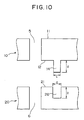
- Figs. 10 to 12 views, each showing junction by press forging the annular groove and the annular protrusion of joined surfaces.
- a gas nozzle plate comprises aluminum plates 10, 20 and 30 having gas path holes and branch formed therein. Each plate is provided with peripheral protrusion 13 and, 23 and a peripheral groove 25 and 35.
- Fig. 3(a) is a plan view of the outer surface (gas supply side) of the aluminum plate 10; Fig. 3(b) a sectional view of the aluminum plate 10; and Fig. 3(c) a plan view of the joined surface of the aluminum plate 10.
- Fig. 4(a) is a perspective view showing the outer surface (gas supply side) of the aluminum plate 10; and Fig. 4(b) a perspective view showing the joined surface of the aluminum plate 10.
- the aluminum plate 10 includes an A gas path hole 1, an H-shaped A gas branch 2, and a B gas path hole 5, which are all formed from the outer surface 11 to the joined surface 12.
- the joined surface 12 includes an annular protrusion 13 formed in the outer periphery, and an annular protrusion 14 formed around the B gas path hole 5.
- Fig. 5(a) is a plan view of the joined surface of the aluminum plate 20 with the aluminum plate 10
- Fig. 5(b) a sectional view of the aluminum plate 20
- Fig. 5(c) a plan view of the joined surface of the aluminum plate 20 with the aluminum plate 30
- Fig. 6(a) is a perspective view showing the joined surface of the aluminum plate 20 with the aluminum plate 10
- Fig. 6(b) a perspective view showing the joined surface of the aluminum plate 20 with the aluminum plate 30.
- the aluminum plate 20 includes a plurality (six in the drawings) of A gas path holes 3 formed from a joined surface 21 to the joined surface 22 of its opposite side.
- Each of the A gas path holes 3 is provided in a position corresponding to the A gas branch 2 having an H groove shape, formed in the aluminum plate 10.
- the aluminum plate 20 also includes a B gas path hole 6, and a B gas branch 7 having a frame-like groove shape, which are formed from the joined surface 21 to the joined surface 22.
- the B gas path hole 6 is provided in a position corresponding to the gas path hole 5 of the aluminum plate 10.
- annular grooves 25 and 26 are formed respectively in the outer periphery and around the B gas path hole 6.
- the annular groove 25 is formed in a position opposite the annular protrusion 13 formed in the joined surface 12 of the aluminum plate 10.
- the annular groove 26 is formed in a position opposite the annular protruded 14 formed in the joined surface 12 of the aluminum plate 10.
- annular protrusion 23 and 24 are formed respectively in the outer periphery and around the A gas path hole 3.
- Fig. 7(a) is a plan view of the joined surface of the aluminum plate 30 with the aluminum plate 20; Fig. 7(b) a sectional view of the aluminum plate 30; and Fig. 7(c) a plan view of the outer surface (gas outlet side) of the aluminum plate 30.
- Fig. 8(a) is a perspective view showing the joined surface of the aluminum plate 30 with the aluminum plate 20; and Fig. 8(b) a perspective view showing the outer surface (gas outlet side) of the aluminum plate 30.
- the aluminum plate 30 includes a plurality (six in the drawings) of A gas path holes 4, and a plurality (twelve in the drawings) of B gas path holes 8, which are formed from a joined surface 31 to a gas outlet surface 32.
- the plurality of A gas path holes 4 are provided in positions respectively corresponding to the plurality of A gas path holes 3 of the aluminum plate 20.
- the plurality of B gas path holes 8 are provided in positions corresponding to the B gas branch 7 of the frame-like groove shape.
- annular grooves 35 and 36 are formed respectively in the outer periphery and around the A gas path hole.
- the annular groove 35 of the outer periphery is formed in a position opposite the annular protrusion 23 formed in the joined surface 22 of the aluminum plate 20.
- the annular groove 36 is formed in a position opposite the annular protrusion 24 formed in the joined surface 22 of the aluminum plate 20.
- the aluminum plate 30 was shown to have six A gas path holes and twelve B gas path holes. This is a simplified drawing designed to facilitate understanding. In practice, however, a number of gas path holes are provided in the gas dispersion plate in a widely dispersed manner. In addition, the H-shaped and frame-like types were shown as the gas branch portions. However, any other types can be used as long as gas is branched and widely dispersed.
- the aluminum plates 10, 20 and 30 prepared in the foregoing manner are then laminated as shown in Figs. 2 and 9.
- the branch 2 of the A gas path hole 1 formed in the aluminum plate 10 is connected to the plurality of A gas path holes 3 of the aluminum plate 20.
- the plurality of A gas path holes 3 arc in turn connected respectively to the A gas path holes 4 of the aluminum plate 30.
- the B gas path hole 5 of the aluminum plate 10 is connected to the B gas path hole 6 of the aluminum plate 20.
- the branch 7 of the B gas path hole 6 is connected to the plurality of B gas path holes 8 of the aluminum plate 30.
- the annular protrusion 13 formed in the outer periphery of the joined surface 12 of the aluminum plate 10 is combined with the annular groove 25 formed in the joined surface 21 of the aluminum plate 20.
- the annular protrusion 14 formed in the joined surface 12 of the aluminum plate 10 is combined with the annular groove 26 formed in the joined surface 21 of the aluminum plate 20.
- annular protrusion 23 formed in the outer periphery of the joined surface 22 of the aluminum plate 20 is combined with the annular groove 35 formed in the joined surface 31 of the aluminum plate 30.
- the annular protrusion 24 formed in the joined surface 22 of the aluminum plate 20 is combined with the annular groove 36 formed in the joined surface 31 of the aluminum plate 30.
- the A gas path holes, the branch thereof, the B gas path holes and the branch thereof of the aluminum plates 10, 20 and 30 are aligned with one another, the annular grooves and the annular protrusion are combined together, and press forging is then executed for junction, thereby unifying the aluminum plates 10, 20 and 30.
- press forging is then executed for junction, thereby unifying the aluminum plates 10, 20 and 30.
- FIG. 10 to 12 is a partially expanded view showing in section the annular grooves and the annular protrusion of the aluminum plates 10 and 20 to be laminated, shown in Fig. 2.
- the annular protrusion 14 is provided around the B gas path hole 5.
- the annular groove 26 is provided for the B gas path hole 6.
- the annular protrusion 14 of the aluminum plate 10 is inserted into the annular groove 26 of the aluminum plate 20, and this portion is subjected to press forging.
- press forging as shown in Fig. 12, the annular protrusion 14 of the aluminum plate 10 is joined to the annular groove 26 of the aluminum plate 10 by filling the inside thereof.
- a specific relation between the annular groove and the annular protrusion is as follows. That is, when a width and a depth of the annular groove 26 are respectively a and b, and a width and a height of the annular protrusion 14 are respectively c and d, the following relation should preferably be set: a ⁇ b ⁇ c ⁇ d and b ⁇ d
- a relation of a>c is set to facilitate the insertion of the annular protrusion 14 into the annular groove 26 and its combination with the same. Even when the relation of a>c is satisfied, however, if the width c of the annular protrusion 14 is too small compared with the width a of the annular groove 26, then the annular protrusion 14 may be bent during press forging, disabling the annular protrusion 14 from filling the annular groove 26. Preferably, therefore, the width c of the annular protrusion 14 should not be too small compared with the width of the annular groove 26. Even in the case of a relation a c, the tip of the annular protrusion is tapered, and sealing can be secured when forcible pressing-in is allowed.
- annular protrusion 14 The relation between the annular protrusion 14 and the annular groove 26 was described. Similarly, the other annular protrusion can be inserted into the annular groove, and these portions are subjected to press forging and compression so as to be joined.
- a gas is passed through the path hole 1, and widely dispersed at the branch surface 2.
- the A gas is then caused to flow out through the number of path holes 3 and 4, and supplied to a film-forming side.
- B gas is passed through the path holes 5 and 6, and widely dispersed at the branch 7.
- the B gas is then caused to flow out through the number of path holes 8, and supplied to the film-forming side.
- the A and B gases are mixed immediately before the substrate, and then a film 38 is formed on the substrate 37.
- sealing is secured for the connected parts of the A gas path holes 3 and 4, because of the junction of the peripheries thereof by press forging and compressing the annular protrusion 24 and the annular groove 36. Accordingly, the leakage of A gas from the connected parts can be prevented, and the incursion of other gases can also be prevented.
- scaling is secured because of the junction by press forging and compressing the annular protrusion 23 and the annular groove 35 in the outer periphery. Accordingly, the leakage of gas from the gas dispersion nozzle plate to the outside can be prevented.
- the second embodiment is different from the first in the positions of annular protruded portions and annular grooves provided in the joined surfaces of the metal members to be laminated.
- Fig. 13(a) is a plan view of the outer surface (gas supply side) of the metal member 10; Fig. 13(b) a sectional view of the metal member 10; and Fig. 13(c) a plan view of the joined surface of the metal member 10.
- Fig. 14(a) is a plan view of the joined surface of the metal member 20 with the metal member 10; Fig. 14(b) a sectional view of the metal member 20; and Fig. 14(c) a plan view of the joined surface of the metal member 20 with the metal member 30.
- Fig. 15(a) is a plan view of the joined surface of the metal member 30 with the metal member 20; Fig. 15(b) a sectional view of the metal member 30; and Fig. 15(c) a plan view of the outer surface (gas outlet side) of the metal member 30.
- the metal member 10 includes an A gas path hole 1, a branch 2 having an H groove shape, and a B gas path hole 5.
- annular protrusion 15 and 14 arc formed respectively around the A gas branch 2 of the H shape, and around the B gas path hole 5.
- the metal member 20 includes a plurality of A gas path holes 3 formed in positions corresponding to the H groove-shaped branch 2 of the metal member 10, a path hole 6 connected to the B gas path hole 5, and a B gas branch 7 having a frame-like groove shape.
- annular groove 27 is provided in the joined surface 21 of the metal member 20, and an annular groove 26 is provided around the gas path hole 6.
- the annular groove 27 is formed in a position opposite the annular protrusion 15 of the metal member 10; and the annular protrusion 26 in a position opposite the annular protrusion 14 of the metal member 10.
- the metal member 30 includes a plurality of A gas path holes 4, and a plurality of B gas path holes 8. Specifically, the plurality of gas path holes 4 are disposed in positions respectively corresponding to the plurality of gas path holes 3 of the metal member 20; and the plurality of gas path holes 8 in positions corresponding to the gas branch portion 7 of the frame-like groove shape.
- annular grooves 35 and 36 are formed respectively in the outer periphery and around the A gas path hole 4. Specifically, the annular groove 35 is formed in a position opposite the annular protrusion 23 formed in the joined surface 22 of the metal member 20; and the annular groove 36 in a position opposite the annular protrusion 24 formed in the joined surface 22 of the metal member 20.
- the metal members 10, 20 and 30 respectively having the gas path holes, the branch, the annular protrusion and the annular grooves are joined together by press forging, and thereby the gas dispersion nozzle plate is manufactured.
- the joined surfaces 12 and 21 of the metal members 10 and 20 are joined together by press forging the annular protrusion 14 and the annular groove 26 around the connected parts of the gas path holes 5 and 6, and by press forging and compressing the annular protrusion 15 and the annular groove 27 around the connected parts of the branch 2 and the plurality of gas path holes 3. Sealing is thus secured to prevent the leakage of gas, and also the incursion of other gases.
- the joined surfaces 22 and 31 of the metal members 20 and 30 are sealed by the annular protrusion 24 and the annular groove 36 around the connected parts of the gas path holes 3 and 4.
- the joined surfaces 22 and 31 of the metal members 20 and 30 are also sealed by the annular protrusion 23 and the annular groove 35 in the outer periphery. Accordingly, the leakage of gas can be prevented, and the incursion of gas can be prevented.
- a gas dispersion nozzle plate is constructed by laminating four metal members, and adapted to disperse each of three kinds of gases widely in stages.
- Fig. 16 is a sectional view of such a gas dispersion nozzle plate constructed by laminating four sheet metal members. The gas dispersion nozzle plate constructed by laminating four metal members 71 to 74 is now described.
- the metal members 71 and 72 are joined together by press forging an annular protrusion 75 and an annular groove 76 in the outer periphery, and an annular protrusion 81 and an annular groove 82 around the connected part of a gas path hole.
- the junction by the annular protrusion and the annular groove is provided so as to prevent the mixing of different kinds of gases at each gas path hole or branch. In Fig. 16, only a portion of the junction is shown, omitting the others.
- the metal members 72 and 73 are joined together by press forging an annular protrusion 77 and an annular groove 78 in the outer periphery, and an annular protrusion 83 and an annular groove 84 around the connected part of a gas path hole.
- the metal members 73 and 74 are joined together by press forging an annular protrusion 79 and an annular groove 80 in the outer periphery, and an annular protrusion 85 and an annular groove 86 around the connected part of a gas path hole.
- a gas is passed through a path hole 101, and widely dispersed at a branch 102.
- the A gas is then caused to flow out through a number of path holes 103, 104 and 105, and supplied to a film-forming side.
- B gas is passed through path holes 111, 112 and 113, and widely dispersed at a branch 114.
- the B gas is then caused to flow out through a number of path holes 115, and supplied to the film-forming side.
- C gas is passed through path holes 121 and 122, and widely dispersed at a branch 123.
- the C gas is then caused to flow out through a number of path holes 124 and 125, and supplied to the film-forming side.
- Each of the A, B and C gases widely dispersed in stages is supplied through the number of path holes to the film-forming side, and mixed with another gas immediately before the substrate to form a film.
- annular grooves are respectively provided in the opposing positions of the joined surfaces of metal members to be laminated, an intermediate metal member is inserted into each of the annular grooves, and then press forging is executed for junction.
- Fig. 17 is an expanded view showing joined parts around the gas path holes 5 and 6 of the aluminum plates 10 and 20.
- an annular groove 60 is formed around the gas path hole 5.
- an annular groove 59 is formed around the gas path hole 6.
- An intermediate metal member 61 is inserted into the annular grooves 59 and 60.
- an aluminum material similar to those for the aluminum plates 10 and 20 should be used. However, one can be selected for use from other aluminum materials.
- the annular grooves 59 and 60 and the intermediate metal member 61 should preferably be formed to satisfy the following relations: A+C ⁇ E, (A ⁇ B+C ⁇ D) ⁇ E ⁇ F, B ⁇ F, D ⁇ F
- a joined part is formed by inserting the intermediate metal member 61 into the annular grooves 60 and 59 of the aluminum plates 10 and 20, executing press forging, and then filling the annular grooves 59 and 60 with the intermediate metal member 60. In this way, sealing is secured to prevent the leakage of gas.
- Figs. 18 and 19 are expanded views of joined parts around the gas path holes 5 and 6 of the aluminum plates 10 and 20, showing other examples of annular groove shapes and intermediate metal members.
- a joined part shown in Fig. 18 is formed in the following manner. That is, in the joined surface 12 of the aluminum plate 10, an annular groove 63 trapezoidal in section is formed around the gas path hole 5. In the joined surface 21 of the aluminum plate 20, an annular groove 62 trapezoidal in shape is formed around the gas path hole 6. An intermediate metal member 64 having a hexagonal shape corresponding to the trapezoidal shapes of the annular grooves 62 and 63 is inserted, and press forging is executed. Then, the annular grooves 62 and 63 arc filled with the intermediate metal member 64. Thus, sealing is secured.
- a joined part shown in Fig. 19 is formed in the following manner. That is, in the joined surface 12 of the aluminum plate 10, an annular groove 66 U-shaped in section is formed around the gas path hole 5. In the joined surface 21 of the aluminum plate 20, an annular groove 65 U-shaped in section is formed around the gas path hole 6. An intermediate metal member 67 having an elliptic shape is inserted into the U-shaped annular grooves 65 and 66, and press forging is executed. Then, the annular grooves 65 and 66 are filled with the intermediate metal member 67. Thus, sealing is secured.
- annular grooves and the intermediate metal member having the shapes shown in Fig. 18 are advantageous in that the machining of the annular grooves is easy, and the insertion of the intermediate member is easy when it is combined with the annular grooves.
- the intermediate metal member having the shape shown in Fig. 19 is advantageous in that the insertion of the intermediate member is easy when it is combined with the annular grooves.
- the fifth embodiment gives another example regarding the shapes of an annular groove and an annular protrusion provided in the opposing positions of the joined surfaces of the metal members to be laminated.
- a joined part shown in Fig. 20 is formed in the following manner. That is, in the joined surface 12 of the aluminum plate 10, an annular protrusion 53 U-shaped in section is formed around the gas path hole 5. In the joined surface 21 of the aluminum plate 20, an annular groove 51 U-shaped in section is formed around the gas path hole 6. Then, a tapered part 52 is provided in the annular protruded groove 51. Accordingly, the insertion of the annular protrusion into the annular groove is facilitated.
- a joined part shown in Fig. 21 is formed in the following manner. That is, in the joined surface 12 of the aluminum plate 10, an annular protrusion 55 having a tapered part 56 and U-shaped in section is formed around the gas path hole 5. In the joined surface 21 of the aluminum plate 20, an annular groove 54 U-shaped in section is formed around the gas path hole 6. The presence of the tapered part 56 in the annular protrusion 55 facilitates the insertion of the annular protrusion into the annular groove.
- a joined part shown in Fig. 22 is formed in the following manner. That is, in the joined surface 12 of the aluminum plate 10, an annular protrusion trapezoidal in section is formed around the gas path hole 5. In the joined surface 21 of the aluminum plate 20, an annular groove 57 trapezoidal in section is formed around the gas path hole 6. The machining of the annular groove and the annular protrusion is easy, and the insertion of the annular protrusion is easy when it is combined with the annular groove.
- Fig. 23 is a perspective view showing the lamination of metal members according to the sixth embodiment; Figs. 24(a), 24(b) and 25 sectional views, each showing the joined surfaces of the metal members to be laminated.
- the sixth embodiment gives a modified example of the gas dispersion nozzle plate constructed by laminating the aluminum plates 10 and 20, described above with reference to the first embodiment, specifically regarding the connection of the B gas path hole 6 between the aluminum plates 10 and 20.
- an A gas path hole 1 and a hole 69 are formed from the outer surface 11 to the joined surface 12.
- an annular groove 25 is formed in the outer periphery, an A gas path hole 3 is formed, and a cylinder 68 having a B gas path hole 6 is protruded.
- the hole 69 of the aluminum plate 10 is tapered from the joined surface 12 to the outer surface 11.
- the cylinder 68 of the aluminum plate 20 is also tapered, and the gas path hole 6 is formed therein.
- the aluminum plates 10, 20, and so on, are laminated, the A gas path hole, its branch, the B gas path hole and its branch are aligned, the annular groove and the annular protrusion are combined together, and press forging and compression arc performed for junction.
- the tapered cylinder 68 is inserted into the hole 69 of the aluminum plate 10 to form a B gas path hole.
- Fig. 25 shows a joined part formed by providing a chamfered part in the joined surface 12 side of the hole 69 of the aluminum plate 10, thereby facilitating the insertion of the tapered cylinder 68 of the aluminum plate 20.
- good sealing is provided by press forging the surfaces of the metal members to be laminated for junction.
- the invention is particularly advantageous in that high scaling is secured by providing the annular groove and the annular protrusion in the opposing positions of the joined surface of the plurality of sheet metal members having fluid paths and/or branch, and press forging these portions for junction, and accordingly the leakage of fluids such as gas or the like can be prevented.
- the invention is also advantageous in that high sealing is secured by providing the annular grooves in the opposing positions of the joined surface of the plurality of metal members having fluid paths and/or branch, and inserting the intermediate metal member for junction, and accordingly the leakage of fluids such as gas or the like can be prevented.
- the annular groove and the annular protrusion are formed by machining, and press forging is executed for junction.
- the problem of gas generation from the inclusion or the like for junction is prevented during use, making it possible to keep cleanness in the chamber of CVD device, the nozzle plate of the invention being disposed therein.
- the problem of solder melting or the like seen in the soldering method is prevented, making it possible to prevent the precisely machined hole or groove from being clogged.
- No sealing members such as an O-ring or the like are necessary, enabling the nozzle plate to be used until the limit of the heat resisting temperature is reached for the laminated metal plates (aluminum or aluminum alloy).
- the composition of an aluminum alloy can be changed, or other metallic materials to be joined by pressure can be used instead.
Landscapes
- Chemical & Material Sciences (AREA)
- Metallurgy (AREA)
- Chemical Kinetics & Catalysis (AREA)
- Engineering & Computer Science (AREA)
- Materials Engineering (AREA)
- Mechanical Engineering (AREA)
- General Chemical & Material Sciences (AREA)
- Organic Chemistry (AREA)
- Pressure Welding/Diffusion-Bonding (AREA)
- Forging (AREA)
- Chemical Vapour Deposition (AREA)
- Laminated Bodies (AREA)
- Nozzles (AREA)
Applications Claiming Priority (2)
| Application Number | Priority Date | Filing Date | Title |
|---|---|---|---|
| JP2000187658 | 2000-06-22 | ||
| JP2000187658A JP3578398B2 (ja) | 2000-06-22 | 2000-06-22 | 成膜用ガス分散プレート及びその製造方法 |
Publications (2)
| Publication Number | Publication Date |
|---|---|
| EP1168420A2 true EP1168420A2 (de) | 2002-01-02 |
| EP1168420A3 EP1168420A3 (de) | 2006-09-13 |
Family
ID=18687601
Family Applications (1)
| Application Number | Title | Priority Date | Filing Date |
|---|---|---|---|
| EP01114529A Withdrawn EP1168420A3 (de) | 2000-06-22 | 2001-06-16 | Düsenplattenvorrichtung zur Zuführung von Flüssigkeiten in dispergierter Form und Herstellungsverfahren dafür |
Country Status (6)
| Country | Link |
|---|---|
| US (2) | US6799735B2 (de) |
| EP (1) | EP1168420A3 (de) |
| JP (1) | JP3578398B2 (de) |
| KR (1) | KR100433110B1 (de) |
| CN (1) | CN1285762C (de) |
| TW (1) | TW508988B (de) |
Cited By (4)
| Publication number | Priority date | Publication date | Assignee | Title |
|---|---|---|---|---|
| WO2008051717A1 (en) | 2006-10-26 | 2008-05-02 | Applied Materials, Inc. | Temperature controlled multi-gas distribution assembly |
| WO2010016852A1 (en) * | 2008-08-08 | 2010-02-11 | International Solar Electric Technology, Inc. | Chemical vapor deposition method and system for semiconductor devices |
| US8263908B2 (en) | 2004-10-08 | 2012-09-11 | Furukawa-Sky Aluminum Corp. | Heater plate and a method for manufacturing the heater plate |
| CN103074605A (zh) * | 2012-12-26 | 2013-05-01 | 光达光电设备科技(嘉兴)有限公司 | 喷淋头及化学气相沉积设备 |
Families Citing this family (46)
| Publication number | Priority date | Publication date | Assignee | Title |
|---|---|---|---|---|
| JP4750258B2 (ja) * | 2000-10-24 | 2011-08-17 | 古河スカイ株式会社 | 流体回路部材の製造方法 |
| JP4750257B2 (ja) * | 2000-10-24 | 2011-08-17 | 古河スカイ株式会社 | 金属部材を接合したヒートプレートの製造方法 |
| JP3946641B2 (ja) * | 2001-01-22 | 2007-07-18 | 東京エレクトロン株式会社 | 処理装置 |
| US6837966B2 (en) * | 2002-09-30 | 2005-01-04 | Tokyo Electron Limeted | Method and apparatus for an improved baffle plate in a plasma processing system |
| KR100558922B1 (ko) * | 2004-12-16 | 2006-03-10 | (주)퓨전에이드 | 박막 증착장치 및 방법 |
| KR101272321B1 (ko) * | 2005-05-09 | 2013-06-07 | 한국에이에스엠지니텍 주식회사 | 복수의 기체 유입구를 가지는 원자층 증착 장치의 반응기 |
| KR100629358B1 (ko) * | 2005-05-24 | 2006-10-02 | 삼성전자주식회사 | 샤워 헤드 |
| US7958887B2 (en) * | 2006-03-10 | 2011-06-14 | Aradigm Corporation | Nozzle pore configuration for intrapulmonary delivery of aerosolized formulations |
| US20100019058A1 (en) * | 2006-09-13 | 2010-01-28 | Vanderzwet Daniel P | Nozzle assembly for cold gas dynamic spray system |
| US7789961B2 (en) * | 2007-01-08 | 2010-09-07 | Eastman Kodak Company | Delivery device comprising gas diffuser for thin film deposition |
| US11136667B2 (en) * | 2007-01-08 | 2021-10-05 | Eastman Kodak Company | Deposition system and method using a delivery head separated from a substrate by gas pressure |
| JP5183935B2 (ja) | 2007-02-26 | 2013-04-17 | Ckd株式会社 | 流路ブロックの製造方法 |
| DE102007026349A1 (de) * | 2007-06-06 | 2008-12-11 | Aixtron Ag | Aus einer Vielzahl diffusionsverschweißter Scheiben bestehender Gasverteiler |
| US8211231B2 (en) * | 2007-09-26 | 2012-07-03 | Eastman Kodak Company | Delivery device for deposition |
| US8398770B2 (en) * | 2007-09-26 | 2013-03-19 | Eastman Kodak Company | Deposition system for thin film formation |
| US8673080B2 (en) | 2007-10-16 | 2014-03-18 | Novellus Systems, Inc. | Temperature controlled showerhead |
| WO2009107522A1 (ja) * | 2008-02-25 | 2009-09-03 | 有限会社 相田製作所 | 二部材の固定構造、及び工作機械の工具ホルダ |
| US8291857B2 (en) | 2008-07-03 | 2012-10-23 | Applied Materials, Inc. | Apparatuses and methods for atomic layer deposition |
| US9034142B2 (en) * | 2009-12-18 | 2015-05-19 | Novellus Systems, Inc. | Temperature controlled showerhead for high temperature operations |
| US9184028B2 (en) | 2010-08-04 | 2015-11-10 | Lam Research Corporation | Dual plasma volume processing apparatus for neutral/ion flux control |
| US8869742B2 (en) * | 2010-08-04 | 2014-10-28 | Lam Research Corporation | Plasma processing chamber with dual axial gas injection and exhaust |
| WO2012122054A2 (en) | 2011-03-04 | 2012-09-13 | Novellus Systems, Inc. | Hybrid ceramic showerhead |
| TW201347035A (zh) * | 2012-02-02 | 2013-11-16 | Greene Tweed Of Delaware | 用於具有延長生命週期的電漿反應器的氣體分散板 |
| US20140026816A1 (en) * | 2012-07-27 | 2014-01-30 | Applied Materials, Inc. | Multi-zone quartz gas distribution apparatus |
| CN103736616B (zh) * | 2013-12-31 | 2016-09-28 | 天津市德中技术发展有限公司 | 集液体的容纳与液体的喷射功能于一体的装置的制作方法 |
| US9198300B2 (en) | 2014-01-23 | 2015-11-24 | Illinois Tool Works Inc. | Flux management system and method for a wave solder machine |
| US9161459B2 (en) | 2014-02-25 | 2015-10-13 | Illinois Tool Works Inc. | Pre-heater latch and seal mechanism for wave solder machine and related method |
| US10741365B2 (en) | 2014-05-05 | 2020-08-11 | Lam Research Corporation | Low volume showerhead with porous baffle |
| CN105446275B (zh) * | 2014-08-12 | 2018-05-25 | 北京北方华创微电子装备有限公司 | 气路界面显示方法和系统 |
| JP5872089B1 (ja) * | 2015-04-27 | 2016-03-01 | 中外炉工業株式会社 | シャワープレート装置 |
| US10378107B2 (en) | 2015-05-22 | 2019-08-13 | Lam Research Corporation | Low volume showerhead with faceplate holes for improved flow uniformity |
| US10023959B2 (en) | 2015-05-26 | 2018-07-17 | Lam Research Corporation | Anti-transient showerhead |
| TWI723024B (zh) * | 2015-06-26 | 2021-04-01 | 美商應用材料股份有限公司 | 用於改良的氣體分配的遞迴注入設備 |
| WO2017127163A1 (en) * | 2016-01-22 | 2017-07-27 | Applied Materials, Inc. | Ceramic showerhead with embedded conductive layers |
| WO2018042876A1 (ja) * | 2016-09-05 | 2018-03-08 | 信越半導体株式会社 | 気相成長装置及びエピタキシャルウェーハの製造方法 |
| WO2018042877A1 (ja) * | 2016-09-05 | 2018-03-08 | 信越半導体株式会社 | 気相成長装置、エピタキシャルウェーハの製造方法及び気相成長装置用のアタッチメント |
| US11154162B2 (en) | 2017-03-14 | 2021-10-26 | Illinois Tool Works Inc. | Cooking appliance and related heater assembly |
| KR102517783B1 (ko) * | 2018-11-28 | 2023-04-04 | (주)포인트엔지니어링 | 반도체 제조 공정용 또는 디스플레이 제조 공정용 프로세스 유체가 통과하는 접합부품 |
| DE102019200012A1 (de) * | 2019-01-02 | 2020-07-02 | Hansgrohe Se | Brausekopf mit Strahlscheibenhaltevorrichtung |
| US11666921B2 (en) | 2019-06-10 | 2023-06-06 | U.S. Mining, Inc. | Systems and methods for crushing clay, transporting clay, and processing clay |
| KR102770274B1 (ko) * | 2019-08-06 | 2025-02-20 | 삼성전자주식회사 | 샤워헤드 및 이를 구비하는 기판 처리장치 |
| JP2022545273A (ja) | 2019-08-23 | 2022-10-26 | ラム リサーチ コーポレーション | 温度制御型のシャンデリア型シャワーヘッド |
| CN119980191A (zh) | 2019-08-28 | 2025-05-13 | 朗姆研究公司 | 金属沉积 |
| JP7540864B2 (ja) * | 2020-06-15 | 2024-08-27 | 東京エレクトロン株式会社 | シャワープレート及び成膜装置 |
| WO2022133434A1 (en) * | 2020-12-17 | 2022-06-23 | Lam Research Corporation | Optimizing edge radical flux in a downstream plasma chamber |
| KR102657134B1 (ko) * | 2022-03-21 | 2024-04-11 | 김형수 | 다색 파운데이션 충진노즐 |
Family Cites Families (11)
| Publication number | Priority date | Publication date | Assignee | Title |
|---|---|---|---|---|
| FR1569990A (de) * | 1968-04-23 | 1969-06-06 | ||
| US4768751A (en) * | 1987-10-19 | 1988-09-06 | Ford Motor Company | Silicon micromachined non-elastic flow valves |
| DE69123932T2 (de) * | 1990-10-18 | 1997-05-22 | Canon Kk | Herstellungsverfahren eines Tintenstrahldruckkopfes |
| JP2509512B2 (ja) * | 1993-03-05 | 1996-06-19 | 株式会社アイピーシー | ドライブプレ―トの製造方法 |
| US5489930A (en) * | 1993-04-30 | 1996-02-06 | Tektronix, Inc. | Ink jet head with internal filter |
| JP3360098B2 (ja) * | 1995-04-20 | 2002-12-24 | 東京エレクトロン株式会社 | 処理装置のシャワーヘッド構造 |
| JP3552154B2 (ja) * | 1998-01-12 | 2004-08-11 | 古河スカイ株式会社 | アルミニウム又はアルミニウム合金部材からなる密封体、並びに半導体製造装置又は薄型ディスプレー製造装置の基板ホルダー及びそれを製造する方法 |
| JP3345852B2 (ja) * | 1998-06-18 | 2002-11-18 | 古河電気工業株式会社 | 半導体製造装置の基盤ホルダー及びその製造方法 |
| US6376815B1 (en) * | 1998-01-12 | 2002-04-23 | Furukawa Electric Co., Ltd. | Highly gas tight substrate holder and method of manufacturing the same |
| JP2000000584A (ja) | 1998-06-16 | 2000-01-07 | Sekisui Chem Co Ltd | 浄化槽 |
| US6110332A (en) * | 1998-10-26 | 2000-08-29 | The Regents Of The University Of California | T-load microchannel array and fabrication method |
-
2000
- 2000-06-22 JP JP2000187658A patent/JP3578398B2/ja not_active Expired - Fee Related
-
2001
- 2001-04-18 TW TW090109313A patent/TW508988B/zh not_active IP Right Cessation
- 2001-05-17 KR KR10-2001-0027061A patent/KR100433110B1/ko not_active Expired - Lifetime
- 2001-06-16 EP EP01114529A patent/EP1168420A3/de not_active Withdrawn
- 2001-06-18 US US09/883,771 patent/US6799735B2/en not_active Expired - Lifetime
- 2001-06-22 CN CNB011220317A patent/CN1285762C/zh not_active Expired - Lifetime
-
2004
- 2004-08-25 US US10/926,167 patent/US7150418B2/en not_active Expired - Lifetime
Cited By (6)
| Publication number | Priority date | Publication date | Assignee | Title |
|---|---|---|---|---|
| US8263908B2 (en) | 2004-10-08 | 2012-09-11 | Furukawa-Sky Aluminum Corp. | Heater plate and a method for manufacturing the heater plate |
| WO2008051717A1 (en) | 2006-10-26 | 2008-05-02 | Applied Materials, Inc. | Temperature controlled multi-gas distribution assembly |
| EP2084735A4 (de) * | 2006-10-26 | 2012-10-31 | Applied Materials Inc | Temperaturgeregelte mehrfach-gasverteilerbaugruppe |
| WO2010016852A1 (en) * | 2008-08-08 | 2010-02-11 | International Solar Electric Technology, Inc. | Chemical vapor deposition method and system for semiconductor devices |
| US8071165B2 (en) | 2008-08-08 | 2011-12-06 | International Solar Electric Technology, Inc. | Chemical vapor deposition method and system for semiconductor devices |
| CN103074605A (zh) * | 2012-12-26 | 2013-05-01 | 光达光电设备科技(嘉兴)有限公司 | 喷淋头及化学气相沉积设备 |
Also Published As
| Publication number | Publication date |
|---|---|
| US20020005442A1 (en) | 2002-01-17 |
| US7150418B2 (en) | 2006-12-19 |
| KR100433110B1 (ko) | 2004-05-28 |
| US20050017100A1 (en) | 2005-01-27 |
| CN1330169A (zh) | 2002-01-09 |
| KR20020000486A (ko) | 2002-01-05 |
| JP3578398B2 (ja) | 2004-10-20 |
| JP2002008993A (ja) | 2002-01-11 |
| CN1285762C (zh) | 2006-11-22 |
| EP1168420A3 (de) | 2006-09-13 |
| TW508988B (en) | 2002-11-01 |
| US6799735B2 (en) | 2004-10-05 |
Similar Documents
| Publication | Publication Date | Title |
|---|---|---|
| US7150418B2 (en) | Nozzle plate member for supplying fluids in dispersed manner and manufacturing method of the same | |
| US6376815B1 (en) | Highly gas tight substrate holder and method of manufacturing the same | |
| DE60022026T2 (de) | Schlauchendanschluss | |
| JP3552154B2 (ja) | アルミニウム又はアルミニウム合金部材からなる密封体、並びに半導体製造装置又は薄型ディスプレー製造装置の基板ホルダー及びそれを製造する方法 | |
| DE69717646T2 (de) | Verbindungsanordnung für ultra-hochvakuum-syteme | |
| JP2025074319A (ja) | 流体送給システム用の溶接蓋体及びプラグ溶接 | |
| AU2004281347A1 (en) | A plate heat exchanger | |
| DE102007051797B3 (de) | Korrosionsbeständige Mikrokanalwärmesenke | |
| JP3836602B2 (ja) | 真空チャンバーの製造方法 | |
| JPH1082591A (ja) | プレート型ヒートパイプおよびその製造方法 | |
| US11958126B2 (en) | Containers for retaining anesthetic agent and manufacturing methods thereof | |
| US7422247B2 (en) | Branch tee fitting | |
| KR20250072351A (ko) | 파이프 블록을 포함하는 배관 시스템 | |
| JP3345852B2 (ja) | 半導体製造装置の基盤ホルダー及びその製造方法 | |
| JP2007086407A (ja) | 大型平面表示装置のシャーシ枠体製造方法およびシャーシ枠体 | |
| JP4750258B2 (ja) | 流体回路部材の製造方法 | |
| JP4750257B2 (ja) | 金属部材を接合したヒートプレートの製造方法 | |
| KR102592097B1 (ko) | 마찰확산접합을 이용한 반도체용 서셉터 부품과 챔버의 결합 구조 및 그 결합 방법 | |
| JPH0719667U (ja) | メタルガスケット | |
| JP2021196040A (ja) | シール構造 | |
| JPH06122071A (ja) | 金属テープはんだ接合装置 | |
| JPH09271935A (ja) | 金属板の面内複合化方法 |
Legal Events
| Date | Code | Title | Description |
|---|---|---|---|
| PUAI | Public reference made under article 153(3) epc to a published international application that has entered the european phase |
Free format text: ORIGINAL CODE: 0009012 |
|
| AK | Designated contracting states |
Kind code of ref document: A2 Designated state(s): AT BE CH CY DE DK ES FI FR GB GR IE IT LI LU MC NL PT SE TR |
|
| AX | Request for extension of the european patent |
Free format text: AL;LT;LV;MK;RO;SI |
|
| RAP1 | Party data changed (applicant data changed or rights of an application transferred) |
Owner name: FURUKAWA-SKY ALUMINUM CORP. |
|
| PUAL | Search report despatched |
Free format text: ORIGINAL CODE: 0009013 |
|
| AK | Designated contracting states |
Kind code of ref document: A3 Designated state(s): AT BE CH CY DE DK ES FI FR GB GR IE IT LI LU MC NL PT SE TR |
|
| AX | Request for extension of the european patent |
Extension state: AL LT LV MK RO SI |
|
| 17P | Request for examination filed |
Effective date: 20070203 |
|
| AKX | Designation fees paid |
Designated state(s): DE |
|
| 17Q | First examination report despatched |
Effective date: 20080108 |
|
| STAA | Information on the status of an ep patent application or granted ep patent |
Free format text: STATUS: EXAMINATION IS IN PROGRESS |
|
| STAA | Information on the status of an ep patent application or granted ep patent |
Free format text: STATUS: THE APPLICATION IS DEEMED TO BE WITHDRAWN |
|
| 18D | Application deemed to be withdrawn |
Effective date: 20170117 |