EP1167680A2 - Ressort de suspension pour volet roulant - Google Patents
Ressort de suspension pour volet roulant Download PDFInfo
- Publication number
- EP1167680A2 EP1167680A2 EP01115004A EP01115004A EP1167680A2 EP 1167680 A2 EP1167680 A2 EP 1167680A2 EP 01115004 A EP01115004 A EP 01115004A EP 01115004 A EP01115004 A EP 01115004A EP 1167680 A2 EP1167680 A2 EP 1167680A2
- Authority
- EP
- European Patent Office
- Prior art keywords
- roller shutter
- tongue
- suspension plate
- recess
- shutter shaft
- Prior art date
- Legal status (The legal status is an assumption and is not a legal conclusion. Google has not performed a legal analysis and makes no representation as to the accuracy of the status listed.)
- Withdrawn
Links
Images

Classifications
-
- E—FIXED CONSTRUCTIONS
- E06—DOORS, WINDOWS, SHUTTERS, OR ROLLER BLINDS IN GENERAL; LADDERS
- E06B—FIXED OR MOVABLE CLOSURES FOR OPENINGS IN BUILDINGS, VEHICLES, FENCES OR LIKE ENCLOSURES IN GENERAL, e.g. DOORS, WINDOWS, BLINDS, GATES
- E06B9/00—Screening or protective devices for wall or similar openings, with or without operating or securing mechanisms; Closures of similar construction
- E06B9/02—Shutters, movable grilles, or other safety closing devices, e.g. against burglary
- E06B9/08—Roll-type closures
- E06B9/11—Roller shutters
- E06B9/17—Parts or details of roller shutters, e.g. suspension devices, shutter boxes, wicket doors, ventilation openings
- E06B9/171—Rollers therefor; Fastening roller shutters to rollers
Definitions
- the present invention relates to a device for the rotatable hanging of a roller shutter shell according to the preamble of claim 1.
- This type is the hanging plate, which is called elongated narrow spring plate is formed on the roller shutter shaft facing end as an exposed single or multi-part undercut tongue formed.
- the end of the suspension plate forms a T-shape there trained tongue itself.
- Roller shutter shafts are manually or via a gear motor-driven, if the over several suspension plates the roller shutter curtain hanging on the roller shutter shaft is moved.
- the Roller shutter shaft rotated until the roller shutter shaft opposite end of the roller shutter on the window ledge or ground and with lamellar armor Slats closed.
- the roller shutter shaft is rotated further, so that the suspension plates in the area of the undercut tongues Bend back.
- the object of the present invention is therefore a Device for the rotatable suspension of a tank To create roller shutters of the type mentioned in the the risk of breaking the neck of the shutter shaft attached tongue of the suspension plate Bending stress significantly reduced, if not at all is avoided.
- the undercut tongue is inside a recess of the suspension plate is parallel to the neck the tongue at least one web delimiting the recess the end of the suspension plate. This is the Bending stress on at least two areas of the end of the suspension plate, which is sufficient to make one Break these areas at appropriate Avoid bending stress. Furthermore, it follows by increasing the bending area, increasing the corresponding counter torque, so that at the end of the A corresponding downward movement of the roller shutter curtain Enlargement of the motor control or the Hand control results in counterforce. In order to go because of the shortened reverse winding movement less bending stresses.
- the undercut tongue will, as has been the case so far has been carried out for insertion into the slot of the Roller shutter shaft at an angle, preferably in a diagonal direction the slot recess is bent elastically so that Side edges of the slot of the roller shutter shaft in the Undercut the tongue.
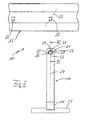
- the in Figs. 1 and 2 device 10 serves for the rotatable hanging of a tank 12 of a roller shutter 11, the roller shutter armor 12 as a lamellar armor or as uniform tank can be formed.
- the device 10 has a hollow roller shutter shaft 13 which For example, via a gearbox by hand or by motor for opening and closing Moving the roller shutter curtain 12 into one of each can be rotated in both directions.
- the embodiment is the roller shutter shaft 13 in section octagonal; but it can also have a different polygonal shape or have a ring shape.
- the device 10 has also a plurality of suspension plates 14, which on their one, 1 lower end with the upper end 21 of Roller shutter curtain 12 are connected and the other 1 upper end 21 into the roller shutter shaft 13 are attached.
- the lower end of the elongated, narrow spring plate trained suspension plate 14 is in the manner of a loop 16 with a transverse profile rail 17 pivotable connected, in which a profile strip 18 of the upper in Fig. 1 Slat 19 of the roller shutter curtain 12 inserted laterally and is attached.
- the upper end 21 of the suspension plate 14 is for releasable hanging in a slot 22 of the Roller shutter shaft 13 formed in a special way.
- the Roller shutter shaft 13 has several seen over its length such preferably arranged evenly distributed Slots 22 in the illustrated embodiment are oblong rectangular, with their long sides in the circumferential direction and its narrow side in Longitudinal direction of the roller shutter shaft 13 extends.
- Slits 22 are provided on a flat surface of the polygon or punched out.
- the end 21 of the Hanging plate 14 has a to the longitudinal axis 24 of the Suspension plate 14 symmetrical recess 26 by two Side bars 27 and 28 and from an end cross piece 29 is limited.
- Inside the recess 26 is a T-shaped one Tongue 31 provided or from the suspension plate 14 punched out.
- the T-shaped tongue 31 has a cross to Longitudinal axis 24 extending retaining web 32, the one narrower neck 33 with the rest of the suspension plate 14 is in one piece. This results in the undercut Tongue 31, the recess 26, as shown in FIG. 2, a bracket-like or C-shape lying on the front has.
- the tongue 31 can be in the same plane as the surrounding ones Webs 27 to 29 of the end 21 lie; but it can also be used for easier threading of the end 21 to be described in the slot 22 of the roller shutter shaft 13 according to the 3 at an acute angle to this or as in FIG. 1 indicated be offset parallel offset.
- the end 21 ' with a recess open in the direction of the longitudinal axis 24 26 ' provided.
- the recess 26 ' has only that two side webs 27 'and 28', during the final cross web eliminated.
- the two side webs 27 'and 28' protrude the retaining web 32 of the tongue 31 somewhat or with complete this.
- the dimensions of the undercut tongue 31 of the suspension plate 14 and the slot 22 of the roller shutter shaft 13 are such matched that the width of the slot 22nd approximately equal to the width of the neck 33 and the width of the Retaining web 32 of the tongue 31 approximately equal to the diagonal 23 of the slot 22 is.
- This allows the threading and unthreading Tongue 31 in or out of the slot 22 in the manner that the end 21 or 21 'of the elastic in itself rotatable suspension plate 14 compared to that Roller shutter curtain facing area of the suspension plate 14 in the direction of the diagonals 23 of the slot 22 of the Roller shutter shaft 13 is rotated so that the tongue 31 inserted diagonally into the slot 22 and turned back can be.
- the holding web 32 engages behind the Side edges of the slot 22, which are then in the area of Neck 33 of the tongue 31 lie.
- the tongue 31 is also shown as T-shaped, it goes without saying that other forms of undercut tongue, such as a semicircular or the like, can also be provided.
- the undercut can be formed by drilling on both sides or by round punchings.
- the distance between the tongue holding web 32 and the edge of the recess 26, 26 ' can only be equal to the punch knife thickness.
- the recess 26, 26 ′ which is arranged within the tongue 31, can be opened laterally, so that the neck of the tongue 31 is only reinforced by a side web of the end of the suspension plate 14.
Landscapes
- Engineering & Computer Science (AREA)
- Structural Engineering (AREA)
- Architecture (AREA)
- Civil Engineering (AREA)
- Operating, Guiding And Securing Of Roll- Type Closing Members (AREA)
Applications Claiming Priority (2)
| Application Number | Priority Date | Filing Date | Title |
|---|---|---|---|
| DE10031275 | 2000-06-27 | ||
| DE2000131275 DE10031275C1 (de) | 2000-06-27 | 2000-06-27 | Flexibles Aufhängeband für Rolladenpanzer |
Publications (2)
| Publication Number | Publication Date |
|---|---|
| EP1167680A2 true EP1167680A2 (fr) | 2002-01-02 |
| EP1167680A3 EP1167680A3 (fr) | 2003-10-08 |
Family
ID=7646971
Family Applications (1)
| Application Number | Title | Priority Date | Filing Date |
|---|---|---|---|
| EP01115004A Withdrawn EP1167680A3 (fr) | 2000-06-27 | 2001-06-20 | Ressort de suspension pour volet roulant |
Country Status (2)
| Country | Link |
|---|---|
| EP (1) | EP1167680A3 (fr) |
| DE (1) | DE10031275C1 (fr) |
Cited By (3)
| Publication number | Priority date | Publication date | Assignee | Title |
|---|---|---|---|---|
| EP1619346A1 (fr) | 2004-07-22 | 2006-01-25 | Jouvence, SAS | Ensemble de lames articulées, tablier de volet roulant et volet roulant ainsi formé |
| EP3916190A1 (fr) * | 2020-05-28 | 2021-12-01 | Gerhard Geiger GmbH & Co. KG | Dispositif de verrouillage à ressort |
| EP4538493A1 (fr) * | 2023-10-12 | 2025-04-16 | CS Plast S.r.l. | Organe d'accouplement pour un volet et fermetures similaires enroulables sur un rouleau d'enroulement associé |
Families Citing this family (3)
| Publication number | Priority date | Publication date | Assignee | Title |
|---|---|---|---|---|
| DE20305389U1 (de) * | 2003-04-03 | 2003-06-12 | Klenk, Gottlieb, 73642 Welzheim | Vorrichtung zum Verbinden eines Rollvorhangs mit einer Wickelwelle |
| FR2896820B1 (fr) * | 2006-01-31 | 2009-07-24 | Deprat Jean Sa Sa | Accessoire de volet roulant et volet roulant equipe d'un accessoire tel que precite |
| ES1068483Y (es) * | 2008-07-23 | 2009-01-16 | Gaviota Simbac Sl | Tirante para persiana enrollable |
Family Cites Families (4)
| Publication number | Priority date | Publication date | Assignee | Title |
|---|---|---|---|---|
| DE1903220U (de) * | 1964-05-15 | 1964-10-29 | Kurt Siebrechtreuter | Loesbare verbindungsvorrichtung einer markise. |
| DE3737216A1 (de) * | 1986-11-05 | 1988-05-19 | Stephan Dick | Rolladen |
| DE29504742U1 (de) * | 1995-03-20 | 1995-05-18 | Dick, Stephan, 56290 Dommershausen | Rolladen |
| DE29603976U1 (de) * | 1996-03-04 | 1996-04-25 | Somfy, Cluses | Hilfsvorrichtung zum Befestigen eines aufrollbaren Elements an einem Aufrollrohr |
-
2000
- 2000-06-27 DE DE2000131275 patent/DE10031275C1/de not_active Expired - Fee Related
-
2001
- 2001-06-20 EP EP01115004A patent/EP1167680A3/fr not_active Withdrawn
Cited By (3)
| Publication number | Priority date | Publication date | Assignee | Title |
|---|---|---|---|---|
| EP1619346A1 (fr) | 2004-07-22 | 2006-01-25 | Jouvence, SAS | Ensemble de lames articulées, tablier de volet roulant et volet roulant ainsi formé |
| EP3916190A1 (fr) * | 2020-05-28 | 2021-12-01 | Gerhard Geiger GmbH & Co. KG | Dispositif de verrouillage à ressort |
| EP4538493A1 (fr) * | 2023-10-12 | 2025-04-16 | CS Plast S.r.l. | Organe d'accouplement pour un volet et fermetures similaires enroulables sur un rouleau d'enroulement associé |
Also Published As
| Publication number | Publication date |
|---|---|
| DE10031275C1 (de) | 2001-10-31 |
| EP1167680A3 (fr) | 2003-10-08 |
Similar Documents
| Publication | Publication Date | Title |
|---|---|---|
| DE69519764T2 (de) | Jalousierbarer Rolladen | |
| DE3318681A1 (de) | Stabjalousie | |
| DE10232536B4 (de) | Rollovorrichtung | |
| EP0653012B1 (fr) | Volet roulant du type jalousie | |
| DE202009005007U1 (de) | Wickelvorrichtung zum Bedecken von Wandöffnungen oder Fenstern | |
| DE4336905C1 (de) | Jalousie zur Regulierung eines Gasstroms | |
| AT399370B (de) | Jalousie | |
| EP1167680A2 (fr) | Ressort de suspension pour volet roulant | |
| DE10225360C1 (de) | Rollo mit seitlicher Führung | |
| EP3521544B1 (fr) | Volet roulant pourvu d'arbre d'enroulement | |
| DE2601663C3 (de) | Kastenrollo | |
| DE202009015473U1 (de) | Lamellenjalousie | |
| EP1203865B1 (fr) | Volet roulant | |
| DE202009001795U1 (de) | Raffstoreanordnung | |
| EP1111185A1 (fr) | Dispositif de sécurité pour volets roulants ou similaire | |
| DE29504742U1 (de) | Rolladen | |
| CH696275A5 (de) | Raffstore mit Wendelager. | |
| DE3927080C2 (de) | Aufwickelvorrichtung | |
| EP1267031A1 (fr) | Dispositif anti-relevage de sécurité de voulet roulant | |
| EP2090736B1 (fr) | Store | |
| DE2210366C3 (de) | Rollgitter, insbesondere aus Leichtmetall | |
| DE20305389U1 (de) | Vorrichtung zum Verbinden eines Rollvorhangs mit einer Wickelwelle | |
| DE202009012188U1 (de) | Sonnenschutzrollo | |
| DE19923724B4 (de) | Jalousie | |
| AT403308B (de) | Jalousierbarer rolladen |
Legal Events
| Date | Code | Title | Description |
|---|---|---|---|
| PUAI | Public reference made under article 153(3) epc to a published international application that has entered the european phase |
Free format text: ORIGINAL CODE: 0009012 |
|
| AK | Designated contracting states |
Kind code of ref document: A2 Designated state(s): AT BE CH CY DE DK ES FI FR GB GR IE IT LI LU MC NL PT SE TR |
|
| AX | Request for extension of the european patent |
Free format text: AL;LT;LV;MK;RO;SI |
|
| PUAL | Search report despatched |
Free format text: ORIGINAL CODE: 0009013 |
|
| AK | Designated contracting states |
Kind code of ref document: A3 Designated state(s): AT BE CH CY DE DK ES FI FR GB GR IE IT LI LU MC NL PT SE TR |
|
| AX | Request for extension of the european patent |
Extension state: AL LT LV MK RO SI |
|
| RIC1 | Information provided on ipc code assigned before grant |
Ipc: 7E 06B 9/173 B Ipc: 7E 06B 9/48 B Ipc: 7E 06B 9/171 A |
|
| AKX | Designation fees paid | ||
| STAA | Information on the status of an ep patent application or granted ep patent |
Free format text: STATUS: THE APPLICATION IS DEEMED TO BE WITHDRAWN |
|
| REG | Reference to a national code |
Ref country code: DE Ref legal event code: 8566 |
|
| 18D | Application deemed to be withdrawn |
Effective date: 20040103 |