EP1163066B1 - Molding method and system with a molding apparatus - Google Patents
Molding method and system with a molding apparatus Download PDFInfo
- Publication number
- EP1163066B1 EP1163066B1 EP00927769A EP00927769A EP1163066B1 EP 1163066 B1 EP1163066 B1 EP 1163066B1 EP 00927769 A EP00927769 A EP 00927769A EP 00927769 A EP00927769 A EP 00927769A EP 1163066 B1 EP1163066 B1 EP 1163066B1
- Authority
- EP
- European Patent Office
- Prior art keywords
- molding
- sand
- squeezing feet
- pattern plate
- frame
- Prior art date
- Legal status (The legal status is an assumption and is not a legal conclusion. Google has not performed a legal analysis and makes no representation as to the accuracy of the status listed.)
- Expired - Lifetime
Links
- 238000000465 moulding Methods 0.000 title claims abstract description 242
- 238000000034 method Methods 0.000 title claims abstract description 42
- 239000003110 molding sand Substances 0.000 claims abstract description 158
- 238000005273 aeration Methods 0.000 claims description 32
- 239000004576 sand Substances 0.000 claims description 30
- 238000012545 processing Methods 0.000 claims description 10
- 238000005259 measurement Methods 0.000 claims description 9
- XLYOFNOQVPJJNP-UHFFFAOYSA-N water Substances O XLYOFNOQVPJJNP-UHFFFAOYSA-N 0.000 claims description 4
- 239000000126 substance Substances 0.000 description 5
- 230000003247 decreasing effect Effects 0.000 description 4
- 238000005266 casting Methods 0.000 description 2
- 238000004891 communication Methods 0.000 description 2
- 238000007796 conventional method Methods 0.000 description 1
- 230000005484 gravity Effects 0.000 description 1
- 238000012360 testing method Methods 0.000 description 1
Images




Classifications
-
- B—PERFORMING OPERATIONS; TRANSPORTING
- B22—CASTING; POWDER METALLURGY
- B22C—FOUNDRY MOULDING
- B22C19/00—Components or accessories for moulding machines
- B22C19/04—Controlling devices specially designed for moulding machines
-
- B—PERFORMING OPERATIONS; TRANSPORTING
- B22—CASTING; POWDER METALLURGY
- B22C—FOUNDRY MOULDING
- B22C15/00—Moulding machines characterised by the compacting mechanism; Accessories therefor
- B22C15/02—Compacting by pressing devices only
- B22C15/08—Compacting by pressing devices only involving pneumatic or hydraulic mechanisms
-
- B—PERFORMING OPERATIONS; TRANSPORTING
- B22—CASTING; POWDER METALLURGY
- B22C—FOUNDRY MOULDING
- B22C15/00—Moulding machines characterised by the compacting mechanism; Accessories therefor
- B22C15/28—Compacting by different means acting simultaneously or successively, e.g. preliminary blowing and finally pressing
Definitions
- the present invention relates to a molding method and system with a molding apparatus. More particularly, it relates to a molding method and system with a molding apparatus by which the density of a mold is made uniform, by which little molding sand overflows the molding apparatus, and by which the amount of any molding sand that must be removed from the mold is less compared to the prior art.
- a pattern plate is surrounded by a molding frame of a molding apparatus.
- the molding frame of the molding apparatus is filled with molding sand by letting it fall from a hopper by gravity. Then the molding sand projecting over the molding frame is swept out by a suitable member so that the upper surface of the molding sand may be flat.
- a conventional molding apparatus supplies molding sand on an entire surface of a pattern plate regardless of different heights of the areas of the surface of the pattern plate.
- molding sand can overflow a molding frame when the molding sand fills it.
- the density of the molding sand varies at various areas on a pattern plate according to the different heights of the patterns on the pattern plate, when the molding sand is squeezed.
- a conventional molding apparatus usually supplies molding sand to a molding frame at a constant in volume over time, so that the density of the molding sand differs at various positions on the pattern plate, although the feed of the molding sand to the molding frame must properly be changed according to the different shapes of patterns.
- the molding sand when under that state the molding sand is squeezed, the resulting mold can project from the molding frame.
- the portion of the mold that projects over the upper level of the molding frame must be removed so that the upper surface of the mold may be aligned with the upper edge of the molding frame.
- an apparatus for removing the molding sand is required.
- the molding sand is spread when it is removed.
- Molding methods where a molding substance filled into a filling cavity is mechanically compressed are known, e.g., from EP 0 673 698 A1, EP 0 295 472 A2, and EP 0 715 914 A1.
- the means used for mechanically compressing the molding substance are kept outside the filling cavity while the same is being filled with the molding substance. Only after the cavity has been filled with the molding substance, the compressing means (which may include a pressure plate and/or a plurality of squeezing feet) are lowered into the cavity to compact the molding substance.
- the present invention provides a molding method according to claim 1 and a molding system according to claim 15.
- the method includes the steps of filling molding sand into a filling cavity defined between a pattern plate, a molding frame put on the pattern plate, and a filling frame put on the molding frame, and compressing the molding sand in the filling cavity by means of a plurality of squeezing feet movably supported by a covering apparatus, the squeezing feet having lower ends which are opposed to surfaces of patterns on the pattern plate.
- the method is characterized by the steps of, prior to filling the molding sand into the filling cavity, moving the squeezing feet downward to enter the filling frame and temporarily holding the squeezing feet at certain positions where certain distances are kept between the lower ends of the squeezing feet and the opposed surfaces of the pattern plate, and filling the molding sand into the filling cavity while the squeezing feet are held at the certain positions within the filling frame.
- the capacity of the filling cavity may be controlled by moving the respective squeezing feet up and down.
- the capacity of the filling cavity may be controlled by changing the distances between the surfaces of the patterns on the pattern plate and all the squeezing feet.
- the positions of the respective squeezing feet can be controlled when any part of the molding sand that is too much or too little is sensed.
- the distances between the surfaces of the patterns on the pattern plate and all the squeezing feet may be controlled when too much or too little molding sand is sensed.
- the step of sensing the molding sand that is partially too much or too little or entirely too much or too little may include the steps of measuring reaction forces of the molding sand to the squeezing feet when the molding sand is compressed in the filling cavity, and executing a calculation based on the measurements of the reaction forces.
- the molding sand can be supplied by supplying compressed air.
- the molding sand may be supplied through a plurality of nozzles.
- the feed of the molding sand may be changed by changing the amount of aeration to the respective nozzles according to the shapes of the patterns on the pattern plate.
- a pressurized airflow or a pressurized air surge may act after the molding sand is supplied.
- the past molding data can be stored in a storage device of a controller of the molding apparatus. Before the relevant operations are performed during the molding operation by the molding apparatus, optimized values on the capacity of the filling cavity, the positions and strength of the aeration, and the strength of the pressurized airflow or the pressurized air surge can be set.
- the past molding data may be connected to a computer that stores molding data for another molding apparatus through a controller of the molding apparatus.
- the results of the calculation by the computer can be used so that optimized values on the capacity of the filling cavity, the positions and strength of the aeration, and the strength of the pressurized airflow or the pressurized air surge can be set.
- the past molding data can be also connected to a computer that stores sand processing or sand mixing data through a controller of the molding apparatus.
- a computer that stores sand processing or sand mixing data through a controller of the molding apparatus.
- the sand mixing data my relate to the compactability of the molding sand and the water content of the molding sand. By referring to that data the capacity of the filling cavity, the positions and strength of the aeration, and the strength of the pressurized airflow or the pressurized air surge can be controlled.
- the molding system comprises a pattern plate, a molding frame to be put on the pattern plate, a filling frame to be put on the molding frame, a covering apparatus having a plurality of movable squeezing feet, the squeezing feet having lower ends which are opposed to surfaces of patterns on the pattern plate, a sand supplying apparatus for supplying molding sand to a filling cavity defined between the pattern plate, the molding frame, and the filling frame, and a control means arranged to control the squeezing feet so as to move the squeezing feet downward to enter the filling frame and temporarily hold the squeezing feet at certain positions where certain distances are kept between the lower ends of the squeezing feet and the opposed surfaces of the pattern plate.
- the molding system is characterized by sensors for measuring reaction forces to respective squeezing feet, a storage device that stores molding data based on the measurements of the sensors for measuring reaction forces, and a distance calculation device for calculating distances between the lower ends of the squeezing feet relating to the filling cavity and the patterns on the pattern plate that are opposed to the lower ends of the squeezing feet.
- the squeezing feet of the covering apparatus may pass through a plate of the covering apparatus to move up and down so that they jointly form an upper surface of the filling cavity.
- Any molding sand that is partially too much or too little may be sensed when the density of a part of the moldis high or low. Too much or too little molding sand may be sensed when the density of all the molding sand is measured to be too high or too low.
- reaction forces to the plurality of squeezing feet act when the molding sand is compressed. Those forces are sensed by respective sensors, for example.
- Past molding data may not only include molding data for an immediately preceding molding, but also molding data previous to it.
- the immediately prior molding data as well as data taken based on some of the previous data may be used.
- the previous molding data may be stored as a data base so that based on this data the capacity of the filling cavity can be controlled by conventional methods such a method of least squares and a fuzzy control method.
- the past molding data may be connected through a communication line such as the internet and radio communications to a computer that stores molding data for another molding apparatus through a controller of the molding apparatus.
- Fig. 1 shows a flowchart of a molding method for a molding apparatus with a molding frame of this invention.
- the method includes steps of defining a cavity that is to be filled with molding sand, supplying molding sand to the cavity, and compressing the molding sand with a plurality of squeezing feet.
- the step of defining a cavity is performed by means of a pattern plate, a molding frame that is put on the pattern plate, a filling frame that is put on the molding frame, and a covering apparatus that has a plurality of squeezing feet.
- the squeezing feet are inserted into the space defined by the filling frame, so that they are arranged opposite respective portions of the casting pattern on the pattern plate. Also, the feet can temporarily be stopped so that certain distances are held between the squeezing feet and the corresponding portions of the casting pattern.
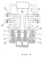
- Fig. 2 is a cross sectional and front view of a main part of a molding apparatus that includes a mechanism to supply molding sand to molding frames and a squeezing apparatus.
- a pattern plate 2 is disposed on a moving table 1, which is intermittently and horizontally moved by means of a conventional mechanism (not shown).
- a molding frame 3 is horizontally and vertically transported over the pattern plate 2 by a frame transporting apparatus (not shown), so that the frame 3 can be put on the pattern plate 2 when the moving table 1 temporarily stops at a certain position.
- a covering apparatus 5 is disposed above the molding frame 3 that is stopped at a certain position.
- the covering apparatus 5 has a plurality of squeezing feet and a filling frame 4.
- the frame 4 is hung from the covering apparatus 5.
- the frame 4 can move up and down over a certain distance from the lower end of the covering apparatus 5.
- the covering apparatus can be moved up and down by means of an actuator (not shown).
- the plurality of the squeezing feet 8 are positioned along the center of the covering apparatus 5 and perform the squeezing operation.
- the covering apparatus 5 has a holding member 6, which is shaped like an inverted box, from which the filling frame 4 is hung.
- the filling frame 4 can move up and down over a certain distance along the holding member 6.
- a square tubular hopper 7 is located on the upper surface of the holding member 6 as a sand supplying apparatus.
- the hopper 7 has a plurality of nozzles at the lower end so as to supply molding sand.
- a plurality of the squeezing feet 8 are arranged like a grid within a lower cavity defined by the holding member 6. The feet can be moved up and down within the lower cavity.
- Each foot 8 is shaped cylindrically.
- each foot 8 is shaped like a cylinder so that the lower part of the foot is closed by a plate while the upper end of it is closed by a plate that has a hole 9. Those plates can be fixed to the foot by means of bolts.
- a piston rod 11 is inserted into the foot 8 after it passes through the hole 9.
- a piston 10 is integrally combined with the piston rod 11. The upper end of the piston rod 11 is fixed to the holding member 6. The foot 8 can be slidably and relatively moved up and down along the piston rod 11.
- a first channel 12 is formed in each piston rod 11 along it and passes through the piston 10.
- a second channel 13 is formed in each piston rod 11 along it, but that channel does not pass through the piston 10.
- the first and second channels 12 and 13 are connected through a directional control valve 14 to an oil-pressure unit (not shown).
- a pressure sensor 15 and a flow-control valve 17 are connected to a line between each first conduit 12 and each directional control valve 14.
- the pressure sensor 15 operates as a reaction force measurement apparatus to measure the reaction forces that are caused to the squeezing feet 8 of the covering apparatus when the molding sand in the sand filling cavity is squeezed.
- the flow-control valve 17 controls the flow rate of pressure oil that flows in the first conduit 12.
- a microcomputer 18 is electrically connected to the pressure sensors 15 and the directional control valves 17.
- a safety valve or a relief valve may be connected to each line between the first channel 12 and the flow-control valve 17.
- the microcomputer 18 operates as a distance calculating apparatus. Based on the results of the measurements of the sensors 15, it calculates the distances between the surfaces of patterns on the pattern plate and the lower ends of the squeeze feet, which ends oppose those surfaces, for the next squeezing operation in the sand filling cavity.
- the squeeze feet are held at certain positions so that the ratios of the distances between the surfaces of the patterns on the pattern plate and the lower ends of the squeeze feet before a squeezing operation is performed to those after a squeezing operation is finished can nearly equal each other.
- the distances between the surfaces of the patterns on the pattern plate and the lower ends of the squeeze feet before a squeezing operation is performed are A and B (as in Fig. 2)
- the distances after a squeezing operation is finished are a and b (as in Fig. 4)
- Nozzles 16 are formed within each of the cavities that are surrounded by a plurality of the squeezing feet 8 and are defined by the holding member 6. Each nozzle 16 is funneled. The outlet of each nozzle 16 is optional. It may be shaped to be circular, elliptical, rectangular, square, etc. Also, such shapes may be combined. The nozzle is not limited to have the shape of a funnel. It may have other shapes (as in Fig. 5). An aeration is performed by passing air through the nozzles 16. The air is pressurized by, for example, a compressor (not shown) so as to cause the aeration. The aeration is performed for each nozzle 16.
- the degree of aeration is changed for each nozzle, so that the amount of molding sand that is supplied to the cavity through the nozzles can be changed according to the patterns on the pattern plate.
- the aeration is performed through the nozzles 16a and 16b, or the aeration is performed through a part of the nozzle 16a, so that the amount of molding sand that is supplied through those nozzles or the part can be increased over the prior art.
- an electromagnetic valve is used to open or close all or some of the nozzles or part of each nozzle.
- the step of defining the molding sand filling cavity allows the molding sand filling cavity to be defined by means of the pattern plate 2, the molding frame 3, which is to be put on the pattern plate 2, the filling frame 4, which is to be put on the molding frame 3, and the covering apparatus 5, which has a plurality of the squeezing feet 8, which squeezing feet can be inserted into the filling frame 4. Also, the squeezing feet 8 can be temporarily held at certain positions so that the lower ends of the squeezing feet and the surfaces of the patterns on the pattern plate are opposed and so that certain distances can be kept between them.
- the molding frame 3 is put on the pattern plate 2
- the filling frame 4 is put on the molding frame 3
- the covering apparatus 5, which has the squeezing feet is put on the filling frame 4.
- some of the directional-control valves 14 are exchanged, so that pressurized oil is supplied through the relevant first channels 12 to the spaces that are defined by the pistons 10 and the squeezing feet 8.
- This allows the squeezing feet 8 to be moved down, as in Fig. 2, so that the distances A and B are kept between the lower ends of the squeezing feet 8 and the corresponding surfaces of the patterns of the pattern plate 2.
- the distances A and B are selected so that the ratios of them to those that will be determined may be substantially close to each other. That is, the squeezing feet 8 that are positioned opposed to the patterns on the pattern plate that are relatively high are moved down so that the amount of molding sand that is to be compressed may be decreased compared to the prior art. In contrast, the squeezing feet 8 that are positioned opposed to the patterns on the pattern plate that are relatively low are moved down just a little so that the amount of molding sand that is to be compressed may increase. Thus, this allows the molding sand filling cavity to be defined by the pattern plate 2, the molding frame 3, the filling frame 4, and the plurality of the squeezing feet 8.
- molding sand is supplied by molding sand supplying mechanism (not shown) to the sand hopper 7, which is positioned at the upper part of the covering apparatus 5, which has a plurality of the squeezing feet 8, so that the molding sand is supplied from the sand hopper 7 through a plurality of the nozzles 16 to the molding sand filling cavity.
- the covering apparatus 5 which has a plurality of the squeezing feet 8 is moved down by an actuator (not shown), so that the molding sand within the molding sand filling cavity is squeezed by the plurality of the squeezing feet 8. If the reaction forces of the molding sand to the squeezing feet 8 become greater than the downward forces of the squeezing feet when the squeezing feet operate, then those squeezing feet will be moved relatively up to the upper position as the covering apparatus moves down, since the relief valve operates to release the oil from the second channels 13. When the covering apparatus 5 moves down to a certain position, all the squeezing feet 8 are moved to the upper position, so that the surface of the molding sand is flat and so that the mold is uniformly squeezed.
- a microcomputer 18 When the squeezing operation is completed, the reaction forces of the molding sand to the squeezing feet 8 (that is, the density of the mold) are sensed by the pressure sensor 15. Based on this measurement, to adjust the positions of the squeezing feet 8 within the molding sand filling cavity a microcomputer 18 generates an order signal to suitably control flow-control valves 17 that were selected for the previous squeezing operation when the molding sand was supplied to the molding sand filling cavity.
- the amount of molding sand that is supplied to the molding sand filling cavity is increased or decreased, so that the density of the mold that is determined when the squeezing operation is performed becomes uniform or the reaction forces that are caused when the squeezing operation is performed become the same.
- oil pressure is used for a driving source to move the squeezing feet.
- Air pressure may also be used for the driving source.
- the squeezing feet may be electrically moved.
- the directional control valve is connected to an air driving source such as an air unit.
- both of the pressures in the spaces that are connected to the first and second channels 12, 13 are controlled, so that the respective positions of the squeezing feet 8 can be gradually adjusted at the upper, middle, and lower positions, etc.
- the position of the filling frame 6, to which the squeezing feet is connected is moved up and down, so that all the distances between the lower ends of the squeezing feet and the opposed surfaces of the patterns on the pattern plate can be synchronously adjusted.
- FIG. 6 shows a flowchart of a squeezing operation that is performed by the second embodiment.
- This flowchart differs from that for the first embodiment in that after a molding sand hopper is filled with molding sand, a pressurized air flow or a pressurized air surge acts on the molding sand, and then the molding sand is compressed by the squeezing feet.
- the second embodiment of this invention includes valves 20 that close the outlets of the nozzles to prevent air from flowing into the molding sand cavity when a pressurized air flow or a pressurized air surge acts, and includes an air supplying apparatus.
- Fig. 7 shows the half of the apparatus denoted by (a). It shows the valve 20 being open.
- Fig. 7 also shows the half of the apparatus denoted by (b). It shows the valve 20 being closed.
- the air supplying apparatus includes an air tank 21 and air valve 22.
- the computer is electrically connected to them to control the pressure of the air that is supplied by the air tank 21 and the opening angle of the air valve 22.
- the apparatus of this second embodiment allows the molding sand to be preliminarily compressed after it is supplied to the molding space. Also, the compressed-air flow can highly compress the surfaces of the mold that contact the sides of the patterns on the pattern plate. The pressurized air surge can highly compress the rear side of the mold.
- Fig. 8 shows a schematic view of a molding apparatus of this embodiment.
- the molding apparatus includes a controller 31 to which a storage device 32 is connected. It stores past molding data.
- Various sensors are electrically connected to the controller 31, so that signals are transmitted from the sensors to the controller 31 and then are stored in the storage device 32.
- Molding data such as on the density of the mold and the capacity of the molding sand filling cavity is taken by a pressure sensor etc. Such data is used to control the capacity of the molding sand filling cavity, the positions and strength of the aeration, and the strength of the pressurized air flow or the pressurized air surge.
- the past molding data is calculated and sent to the actuators.
- the past molding data can be sent through the controller of the molding apparatus with frames to a computer of another molding apparatus (not shown) that is used to store molding data.
- a central computer, a data server-type computer, etc. may be used for such a computer.
- the results calculated by the computer are transmitted to a controller of an operational molding apparatus, so that the capacity of the molding sand filling cavity, the positions and strength of the aeration, and the strength of the pressurized air flow or the pressurized air surge can be optimized.
- a computer that stores sand-mixing or sand-processing data can be connected to the controller of the molding apparatus with frames, so that based on that data the optimal value on the capacity of the molding sand filling cavity, the positions and strength of the aeration, and the strength of the pressurized air flow or the pressurized air surge can be set.
- the compactability of the molding sand that represents what percent of the molding sand is compressed when a certain test load bears on it
- the data is stored in a computer that is electrically connected to a mixing controller that a mixing apparatus has.
- the capacity of the molding sand filling cavity, the positions and strength of the aeration, and the strength of the pressurized air flow or the pressurized air surge can be controlled.
- molding data can be commonly used between the computers, so that it ensures that a more precise control can be achieved.
- the molding method for a molding apparatus with molding frames includes steps of defining a molding sand filling cavity by means of a pattern plate, a molding frame that can be put on the pattern plate, a filling frame that can be put on the molding frame, and a covering apparatus having a plurality of squeezing feet that can enter the filling frame and that can be temporarily held at certain positions where certain distances are kept between the lower ends of the squeezing feet and surfaces of patterns on the pattern plate, which surfaces are opposed to the lower ends, supplying molding sand to the molding sand filling cavity, and compressing the molding sand by means of the squeezing feet.
- the molding sand that must be removed can be minimized.
- the density of the mold within the molding frame can be uniform.
- the molding sand that must be removed can be minimized. Also, the density of the mold within the molding frame can be uniform.
- the molding sand filling cavity can be defined so as to prevent any lack of molding sand in the entire mold. Also, the density of the mold within the molding frame can be uniform.
- the entire mold can be prevented from lacking any molding sand.
- the molding sand filling cavity can be accurately defined.
- the molding sand that must be removed can be minimized.
- the density of the mold within the molding frame can be uniform.
- the step of sensing the molding sand that is partially too much or too little or that is entirely too much or too little includes the steps of measuring the reaction forces of the molding sand to the squeezing feet when the molding sand is squeezed in the molding sand filling cavity, and executing a calculation based on the measurements of the reaction forces, the molding sand filling cavity can be accurately defined.
- the molding sand that must be removed can be minimized.
- the density of the mold within the molding frame can be uniform.
- the amount of molding sand that overflows the molding frame when the molding sand is supplied to it can be decreased over the prior art.
- portions of the mold where it is difficult to supply the molding sand can be removed.
- the feed of the molding sand can be easily changed according to the patterns on the pattern plate.
- the molding apparatus can have flexibility because the positions and strength of the supplied compressed air can be changed.
- the precompression allows the mold to be more highly compressed so that its density is uniform.
- the molding apparatus becomes stable, so that the molding sand that must be removed can be minimized. Also, the density of the mold within the molding frame can be uniform.
- the molding method for a molding apparatus with molding frames wherein the past molding data is stored in a storage device of a controller of the molding apparatus with molding frames, and wherein before the relevant operations are performed during the molding operation by the molding apparatus with molding frames optimized values on the capacity of the molding sand filling cavity, the positions and strength of the aeration, and the strength of the pressurized air flow or the pressurized air surge are set, the previous data can be effectively used.
- This method can essentially be used for a molding operation where molding sand that has variable factors is molded.
- the molding data can be used for various molding apparatuses that even have different sizes, different types, and different positions and strengths of compressed-air flows and aeration.
- the molding method for a molding apparatus with molding frames wherein the past molding data is also connected to a computer that stores sand processing or sand mixing data through the controller of the molding apparatus with molding frames, and wherein by making reference to the sand processing or sand mixing data optimized values on the capacity of the molding sand filling cavity, the positions and strength of the aeration, and the strength of the pressurized air flow or the pressurized air surge are set, the molding sand processing data and the molding sand mixing data can be used so that the molding can surely be performed according to the type of molding sands.
- the molding method for a molding apparatus with molding frames wherein the sand mixing data relates to the compactability of the molding sand and the water content of the molding sand, and by referring to that data, the capacity of the molding sand filling cavity, the positions and strength of the aeration, and the strength of the pressurized air flow or the pressurized air surge are controlled, the molding can surely be performed.
- the molding system with molding frames having a pattern plate, a molding frame that can be put on the pattern plate, a filling frame that can be put on the molding frame, a covering apparatus having a plurality of squeezing feet that can enter the filling frame and that can be temporarily held at certain positions where certain distances are kept between the lower ends of the squeezing feet and surfaces of patterns on the pattern plate, which surfaces are opposed to the lower ends, and a sand supplying apparatus for supplying molding sand to the molding sand filling cavity that is defined by the pattern plate, the molding frame, the filling frame, and the covering apparatus, which system is characterized by sensors for measuring the reaction forces to respective squeezing feet, a storage device that stores molding data based on the measurements of the sensors for measuring reaction forces, and a distance calculation device for calculating distances between the lower ends of the squeezing feet relating to the molding sand filling cavity and the patterns on the pattern plate that are opposed to the lower ends of the squeezing feet,
- the sand supplying apparatus has a plurality of nozzles, positions to which it is difficult to supply molding sand can be decreased over the prior art.
- positions to which molding sand is supplied can be selected. Also, an excess of and lack of the molding sand can be overcome.
- the molding system further including a closing member that closes the lower parts of the nozzles, and an air supplying apparatus for introducing air after the molding sand is supplied, the molding sand can be prevented from reversely flowing to the molding sand supplying apparatus.
- molding data that is stored in a storage device of a controller of a molding apparatus with molding frames can be used as past molding data
- molding data that is stored in a storage device of a controller of the molding apparatus can be used as previous molding data, so that experiences can be effectively used when the molding apparatus is controlled.
- the molding data can be used for various molding apparatuses that even have different sizes, different types, and different positions and strengths of compressed-air flows and aeration.
- the sand processing data and the sand mixing data can be used so that a molding operation can be surely be performed according to the type of molding sands.
Landscapes
- Engineering & Computer Science (AREA)
- Mechanical Engineering (AREA)
- Casting Devices For Molds (AREA)
- Injection Moulding Of Plastics Or The Like (AREA)
- Encapsulation Of And Coatings For Semiconductor Or Solid State Devices (AREA)
- Heating, Cooling, Or Curing Plastics Or The Like In General (AREA)
Applications Claiming Priority (3)
| Application Number | Priority Date | Filing Date | Title |
|---|---|---|---|
| JP2000005378A JP3413798B2 (ja) | 2000-01-14 | 2000-01-14 | 枠付造型装置の造型方法及び造型システム |
| JP2000005378 | 2000-01-14 | ||
| PCT/JP2000/003099 WO2001051235A1 (en) | 2000-01-14 | 2000-05-15 | Molding method and system with a molding apparatus |
Publications (2)
| Publication Number | Publication Date |
|---|---|
| EP1163066A1 EP1163066A1 (en) | 2001-12-19 |
| EP1163066B1 true EP1163066B1 (en) | 2005-07-27 |
Family
ID=18534052
Family Applications (1)
| Application Number | Title | Priority Date | Filing Date |
|---|---|---|---|
| EP00927769A Expired - Lifetime EP1163066B1 (en) | 2000-01-14 | 2000-05-15 | Molding method and system with a molding apparatus |
Country Status (13)
| Country | Link |
|---|---|
| US (1) | US6470953B1 (cg-RX-API-DMAC7.html) |
| EP (1) | EP1163066B1 (cg-RX-API-DMAC7.html) |
| JP (1) | JP3413798B2 (cg-RX-API-DMAC7.html) |
| KR (1) | KR100623056B1 (cg-RX-API-DMAC7.html) |
| CN (1) | CN1263566C (cg-RX-API-DMAC7.html) |
| AT (1) | ATE300375T1 (cg-RX-API-DMAC7.html) |
| BR (1) | BR0009015A (cg-RX-API-DMAC7.html) |
| DE (1) | DE60021538T2 (cg-RX-API-DMAC7.html) |
| ES (1) | ES2246851T3 (cg-RX-API-DMAC7.html) |
| ID (1) | ID30244A (cg-RX-API-DMAC7.html) |
| TR (1) | TR200102681T1 (cg-RX-API-DMAC7.html) |
| TW (1) | TW461832B (cg-RX-API-DMAC7.html) |
| WO (1) | WO2001051235A1 (cg-RX-API-DMAC7.html) |
Families Citing this family (21)
| Publication number | Priority date | Publication date | Assignee | Title |
|---|---|---|---|---|
| US6749003B2 (en) * | 2000-04-13 | 2004-06-15 | Sintokogio, Ltd. | Compressing method for casting sand and device therefor |
| CN1214880C (zh) * | 2000-04-21 | 2005-08-17 | 新东工业株式会社 | 铸型造型方法及装置 |
| CN1310718C (zh) * | 2001-03-16 | 2007-04-18 | 新东工业株式会社 | 压实型砂的方法和装置 |
| JP3729197B2 (ja) * | 2001-08-06 | 2005-12-21 | 新東工業株式会社 | 鋳型造型機をモニタする方法及びシステム |
| WO2005058528A1 (ja) * | 2003-12-18 | 2005-06-30 | Sintokogio, Ltd. | 鋳枠無し上・下鋳型の造型方法、その装置及びマッチプレートの交換方法 |
| EP1726382B1 (en) * | 2004-03-18 | 2011-05-11 | Sintokogio, Ltd. | Method of forming molding-flask-less, upper and lower molds and device therefor |
| JP2006312170A (ja) * | 2005-05-06 | 2006-11-16 | Sintokogio Ltd | 鋳枠無し上・下鋳型の造型装置におけるマッチプレートの交換方法 |
| JP4289432B2 (ja) * | 2005-06-13 | 2009-07-01 | 新東工業株式会社 | 鋳枠無し上鋳型および下鋳型の造型装置 |
| KR100949623B1 (ko) * | 2005-08-10 | 2010-03-26 | 신토고교 가부시키가이샤 | 상·하 주형의 조형방법 및 그 장치 |
| JP5071591B2 (ja) * | 2009-12-04 | 2012-11-14 | 新東工業株式会社 | 鋳型造型装置及び鋳型造型方法 |
| CN201677008U (zh) * | 2010-02-24 | 2010-12-22 | 新东工业株式会社 | 铸型造型装置 |
| RU2017131508A (ru) | 2015-03-10 | 2019-04-10 | Синтокогио, Лтд. | Способ управления процессом литья на основе свойств формовочной смеси |
| DE102015205058A1 (de) * | 2015-03-20 | 2016-09-22 | Gelson G. Montero | Verfahren und Vorrichtung zum Herstellen einer Gussform für den Sandguss |
| JP6665935B2 (ja) * | 2016-07-20 | 2020-03-13 | 新東工業株式会社 | 鋳型造型方法 |
| CN106563776A (zh) * | 2016-10-28 | 2017-04-19 | 宁夏共享模具有限公司 | 铸造造型过程的控制系统和控制方法 |
| EP3610966B1 (en) * | 2018-03-27 | 2023-10-04 | Künkel Wagner Germany GmbH | Method and machine for producing a mould portion |
| JP7196911B2 (ja) | 2018-05-07 | 2022-12-27 | 新東工業株式会社 | 生型造型センサー、及び、生型造型性の評価方法 |
| CN112292220A (zh) * | 2018-06-15 | 2021-01-29 | 新东工业株式会社 | 湿砂模造型传感器及湿砂模造型性的评价方法 |
| DE112019003025T5 (de) * | 2018-06-15 | 2021-03-18 | Sintokogio, Ltd. | Form-Formungseinrichtung, Formqualitäts-Evaluierungseinrichtung und Formqualitäts-Evaluierungsverfahren |
| CN112334248A (zh) * | 2018-06-15 | 2021-02-05 | 新东工业株式会社 | 铸模造型装置以及铸模造型装置的控制方法 |
| CN112828248A (zh) * | 2021-02-22 | 2021-05-25 | 临沂市卓杰机械有限公司 | 预压结构及射砂机 |
Family Cites Families (13)
| Publication number | Priority date | Publication date | Assignee | Title |
|---|---|---|---|---|
| DE263977C (cg-RX-API-DMAC7.html) * | ||||
| DE673698C (de) * | 1936-12-31 | 1939-03-28 | Eugen Wenner | Vorrichtung zum selbsttaetigen Auftragen von Bohnermasse auf den Fussboden |
| US2959828A (en) * | 1958-06-30 | 1960-11-15 | Herman Pneumatic Machine Co | Foundry mold forming |
| ES337872A1 (es) * | 1966-12-28 | 1968-03-01 | Heinrich Wagner Maschinenfrabr | Un dispositivo para comprimir la arena de moldeo durante laconfeccion de moldes de fundicion. |
| US3586093A (en) * | 1968-09-19 | 1971-06-22 | Spo Inc | Foundry squeeze mechanism |
| US3589431A (en) * | 1969-01-09 | 1971-06-29 | Harrison E Fellows | Mold making equipment utilizing vertical mold blowing and plural rammers |
| DE3740185A1 (de) * | 1987-06-13 | 1989-06-08 | Badische Maschf Gmbh | Verfahren und vorrichtung zum verdichten von formstoff in giesserei-formmaschinen |
| DE4092542C2 (de) * | 1990-03-20 | 1993-11-18 | Dansk Ind Syndikat | Verfahren zur Herstellung einer Reihe von Gießformen oder Formteilen und Vorrichtung zum Ausführen des Verfahrens |
| DK169236B1 (da) * | 1993-07-20 | 1994-09-19 | Dansk Ind Syndikat | Fremgangsmåde ved fremstilling af støbeforme eller dele af sådanne ved sammenpresning af partikelmateriale samt apparat til udøvelse af fremgangsmåden |
| JPH0771721A (ja) * | 1993-09-01 | 1995-03-17 | Yamamoto Mfg Co Ltd | 熱風生成用の燃焼装置 |
| DE4409791A1 (de) * | 1994-03-22 | 1995-09-28 | Wagner Heinrich Sinto Masch | Vorrichtung zur Herstellung von Gießformen |
| JPH08164444A (ja) * | 1994-12-09 | 1996-06-25 | Sintokogio Ltd | 鋳型造型機 |
| EP0867242B1 (en) * | 1997-03-28 | 2000-08-23 | Sintokogio, Ltd. | Method and apparatus for pre-compacting molding sand |
-
2000
- 2000-01-14 JP JP2000005378A patent/JP3413798B2/ja not_active Expired - Fee Related
- 2000-03-15 ID IDW00200101987A patent/ID30244A/id unknown
- 2000-05-15 KR KR1020017011608A patent/KR100623056B1/ko not_active Expired - Lifetime
- 2000-05-15 EP EP00927769A patent/EP1163066B1/en not_active Expired - Lifetime
- 2000-05-15 BR BRPI0009015-8A patent/BR0009015A/pt not_active IP Right Cessation
- 2000-05-15 DE DE60021538T patent/DE60021538T2/de not_active Expired - Lifetime
- 2000-05-15 WO PCT/JP2000/003099 patent/WO2001051235A1/en not_active Ceased
- 2000-05-15 ES ES00927769T patent/ES2246851T3/es not_active Expired - Lifetime
- 2000-05-15 AT AT00927769T patent/ATE300375T1/de not_active IP Right Cessation
- 2000-05-15 US US09/570,681 patent/US6470953B1/en not_active Expired - Lifetime
- 2000-05-15 CN CNB008067937A patent/CN1263566C/zh not_active Expired - Lifetime
- 2000-05-15 TR TR2001/02681T patent/TR200102681T1/xx unknown
- 2000-08-25 TW TW089117172A patent/TW461832B/zh not_active IP Right Cessation
Also Published As
| Publication number | Publication date |
|---|---|
| KR100623056B1 (ko) | 2006-09-18 |
| CN1349441A (zh) | 2002-05-15 |
| ID30244A (id) | 2001-11-15 |
| TR200102681T1 (tr) | 2002-03-21 |
| WO2001051235A1 (en) | 2001-07-19 |
| EP1163066A1 (en) | 2001-12-19 |
| BR0009015A (pt) | 2001-12-26 |
| DE60021538D1 (de) | 2005-09-01 |
| CN1263566C (zh) | 2006-07-12 |
| JP2001198651A (ja) | 2001-07-24 |
| KR20010113741A (ko) | 2001-12-28 |
| DE60021538T2 (de) | 2006-04-27 |
| ATE300375T1 (de) | 2005-08-15 |
| US6470953B1 (en) | 2002-10-29 |
| BR0009015B1 (cg-RX-API-DMAC7.html) | 2009-01-13 |
| TW461832B (en) | 2001-11-01 |
| JP3413798B2 (ja) | 2003-06-09 |
| ES2246851T3 (es) | 2006-03-01 |
Similar Documents
| Publication | Publication Date | Title |
|---|---|---|
| US6470953B1 (en) | Molding method and system with a molding apparatus | |
| US3659642A (en) | Apparatus for compacting a moulding mixture | |
| EP1738847B1 (en) | Method for manufacturing sandmold | |
| US6684933B2 (en) | Method and apparatus for compacting molding sand | |
| EP1867410A1 (en) | Sand-introducing device using air, and method apparatus for producing a mold | |
| JP2701002B2 (ja) | 粒状材料を突き固めることにより鋳型または鋳型部分を製造する方法および装置 | |
| US4531565A (en) | Gas hardening type molding machine | |
| CA1127823A (en) | Method of and apparatus for molding a drag mold part | |
| JP3092764B2 (ja) | 吹込み式鋳型造型方法 | |
| US8567478B2 (en) | Method for making upper and lower molds and an apparatus therefor | |
| US3880223A (en) | Apparatus for automatically producing mold parts | |
| JPS6111140B2 (cg-RX-API-DMAC7.html) | ||
| JP4092673B2 (ja) | ブロースクイズ式鋳型造型機における鋳型造型方法 | |
| JP3833015B2 (ja) | 鋳型造型装置における遮蔽部材の位置制御方法およびそのシステム | |
| KR101106868B1 (ko) | 주물사 도입식 주형 조형 장치 | |
| TW202000335A (zh) | 鑄模造型裝置及鑄模造型裝置之控制方法 | |
| KR0180355B1 (ko) | 진공주형의 가압장치 | |
| US4197901A (en) | Foundry sand molding apparatus | |
| US5645777A (en) | Dispensing apparatus | |
| JPS6110828Y2 (cg-RX-API-DMAC7.html) | ||
| JP2001225149A (ja) | ブロースクイズ式鋳型造型機における鋳型造型方法 | |
| JPH09225583A (ja) | 中子造型方法及び装置 | |
| JPH07314084A (ja) | 減圧鋳型造型用砂入れ装置 | |
| GB2199523A (en) | Compacting a moulding mixture by a pressurised gas wave | |
| JPS6056444A (ja) | 生砂中子造型機における生砂の吹込み圧力制御方法 |
Legal Events
| Date | Code | Title | Description |
|---|---|---|---|
| PUAI | Public reference made under article 153(3) epc to a published international application that has entered the european phase |
Free format text: ORIGINAL CODE: 0009012 |
|
| 17P | Request for examination filed |
Effective date: 20010911 |
|
| AK | Designated contracting states |
Kind code of ref document: A1 Designated state(s): AT BE CH CY DE DK ES FI FR GB GR IE IT LI LU MC NL PT SE |
|
| 17Q | First examination report despatched |
Effective date: 20040220 |
|
| GRAP | Despatch of communication of intention to grant a patent |
Free format text: ORIGINAL CODE: EPIDOSNIGR1 |
|
| GRAS | Grant fee paid |
Free format text: ORIGINAL CODE: EPIDOSNIGR3 |
|
| GRAA | (expected) grant |
Free format text: ORIGINAL CODE: 0009210 |
|
| AK | Designated contracting states |
Kind code of ref document: B1 Designated state(s): AT BE CH CY DE DK ES FI FR GB GR IE IT LI LU MC NL PT SE |
|
| PG25 | Lapsed in a contracting state [announced via postgrant information from national office to epo] |
Ref country code: BE Free format text: LAPSE BECAUSE OF FAILURE TO SUBMIT A TRANSLATION OF THE DESCRIPTION OR TO PAY THE FEE WITHIN THE PRESCRIBED TIME-LIMIT Effective date: 20050727 Ref country code: FI Free format text: LAPSE BECAUSE OF FAILURE TO SUBMIT A TRANSLATION OF THE DESCRIPTION OR TO PAY THE FEE WITHIN THE PRESCRIBED TIME-LIMIT Effective date: 20050727 Ref country code: NL Free format text: LAPSE BECAUSE OF FAILURE TO SUBMIT A TRANSLATION OF THE DESCRIPTION OR TO PAY THE FEE WITHIN THE PRESCRIBED TIME-LIMIT Effective date: 20050727 Ref country code: AT Free format text: LAPSE BECAUSE OF FAILURE TO SUBMIT A TRANSLATION OF THE DESCRIPTION OR TO PAY THE FEE WITHIN THE PRESCRIBED TIME-LIMIT Effective date: 20050727 |
|
| REG | Reference to a national code |
Ref country code: GB Ref legal event code: FG4D |
|
| REG | Reference to a national code |
Ref country code: CH Ref legal event code: EP |
|
| REG | Reference to a national code |
Ref country code: IE Ref legal event code: FG4D |
|
| REG | Reference to a national code |
Ref country code: CH Ref legal event code: NV Representative=s name: SCHMAUDER & PARTNER AG PATENTANWALTSBUERO |
|
| REF | Corresponds to: |
Ref document number: 60021538 Country of ref document: DE Date of ref document: 20050901 Kind code of ref document: P |
|
| PG25 | Lapsed in a contracting state [announced via postgrant information from national office to epo] |
Ref country code: SE Free format text: LAPSE BECAUSE OF FAILURE TO SUBMIT A TRANSLATION OF THE DESCRIPTION OR TO PAY THE FEE WITHIN THE PRESCRIBED TIME-LIMIT Effective date: 20051027 Ref country code: DK Free format text: LAPSE BECAUSE OF FAILURE TO SUBMIT A TRANSLATION OF THE DESCRIPTION OR TO PAY THE FEE WITHIN THE PRESCRIBED TIME-LIMIT Effective date: 20051027 Ref country code: GR Free format text: LAPSE BECAUSE OF FAILURE TO SUBMIT A TRANSLATION OF THE DESCRIPTION OR TO PAY THE FEE WITHIN THE PRESCRIBED TIME-LIMIT Effective date: 20051027 |
|
| PG25 | Lapsed in a contracting state [announced via postgrant information from national office to epo] |
Ref country code: PT Free format text: LAPSE BECAUSE OF FAILURE TO SUBMIT A TRANSLATION OF THE DESCRIPTION OR TO PAY THE FEE WITHIN THE PRESCRIBED TIME-LIMIT Effective date: 20051227 |
|
| NLV1 | Nl: lapsed or annulled due to failure to fulfill the requirements of art. 29p and 29m of the patents act | ||
| REG | Reference to a national code |
Ref country code: ES Ref legal event code: FG2A Ref document number: 2246851 Country of ref document: ES Kind code of ref document: T3 |
|
| PG25 | Lapsed in a contracting state [announced via postgrant information from national office to epo] |
Ref country code: IE Free format text: LAPSE BECAUSE OF NON-PAYMENT OF DUE FEES Effective date: 20060515 |
|
| PG25 | Lapsed in a contracting state [announced via postgrant information from national office to epo] |
Ref country code: MC Free format text: LAPSE BECAUSE OF NON-PAYMENT OF DUE FEES Effective date: 20060531 |
|
| PLBE | No opposition filed within time limit |
Free format text: ORIGINAL CODE: 0009261 |
|
| STAA | Information on the status of an ep patent application or granted ep patent |
Free format text: STATUS: NO OPPOSITION FILED WITHIN TIME LIMIT |
|
| 26N | No opposition filed |
Effective date: 20060428 |
|
| EN | Fr: translation not filed | ||
| PG25 | Lapsed in a contracting state [announced via postgrant information from national office to epo] |
Ref country code: FR Free format text: LAPSE BECAUSE OF FAILURE TO SUBMIT A TRANSLATION OF THE DESCRIPTION OR TO PAY THE FEE WITHIN THE PRESCRIBED TIME-LIMIT Effective date: 20060922 |
|
| REG | Reference to a national code |
Ref country code: IE Ref legal event code: MM4A |
|
| PG25 | Lapsed in a contracting state [announced via postgrant information from national office to epo] |
Ref country code: LU Free format text: LAPSE BECAUSE OF NON-PAYMENT OF DUE FEES Effective date: 20060515 |
|
| PG25 | Lapsed in a contracting state [announced via postgrant information from national office to epo] |
Ref country code: FR Free format text: LAPSE BECAUSE OF FAILURE TO SUBMIT A TRANSLATION OF THE DESCRIPTION OR TO PAY THE FEE WITHIN THE PRESCRIBED TIME-LIMIT Effective date: 20050727 Ref country code: CY Free format text: LAPSE BECAUSE OF FAILURE TO SUBMIT A TRANSLATION OF THE DESCRIPTION OR TO PAY THE FEE WITHIN THE PRESCRIBED TIME-LIMIT Effective date: 20050727 |
|
| REG | Reference to a national code |
Ref country code: CH Ref legal event code: PCAR Free format text: SCHMAUDER & PARTNER AG PATENT- UND MARKENANWAELTE VSP;ZWAENGIWEG 7;8038 ZUERICH (CH) |
|
| PGFP | Annual fee paid to national office [announced via postgrant information from national office to epo] |
Ref country code: GB Payment date: 20150529 Year of fee payment: 16 |
|
| GBPC | Gb: european patent ceased through non-payment of renewal fee |
Effective date: 20160515 |
|
| PG25 | Lapsed in a contracting state [announced via postgrant information from national office to epo] |
Ref country code: GB Free format text: LAPSE BECAUSE OF NON-PAYMENT OF DUE FEES Effective date: 20160515 |
|
| PGFP | Annual fee paid to national office [announced via postgrant information from national office to epo] |
Ref country code: DE Payment date: 20190521 Year of fee payment: 20 Ref country code: IT Payment date: 20190527 Year of fee payment: 20 Ref country code: ES Payment date: 20190620 Year of fee payment: 20 |
|
| PGFP | Annual fee paid to national office [announced via postgrant information from national office to epo] |
Ref country code: CH Payment date: 20190521 Year of fee payment: 20 |
|
| REG | Reference to a national code |
Ref country code: DE Ref legal event code: R071 Ref document number: 60021538 Country of ref document: DE |
|
| REG | Reference to a national code |
Ref country code: CH Ref legal event code: PL |
|
| REG | Reference to a national code |
Ref country code: ES Ref legal event code: FD2A Effective date: 20220103 |
|
| PG25 | Lapsed in a contracting state [announced via postgrant information from national office to epo] |
Ref country code: ES Free format text: LAPSE BECAUSE OF EXPIRATION OF PROTECTION Effective date: 20200516 |