EP1162864B1 - Speaker structure - Google Patents
Speaker structure Download PDFInfo
- Publication number
- EP1162864B1 EP1162864B1 EP01304973A EP01304973A EP1162864B1 EP 1162864 B1 EP1162864 B1 EP 1162864B1 EP 01304973 A EP01304973 A EP 01304973A EP 01304973 A EP01304973 A EP 01304973A EP 1162864 B1 EP1162864 B1 EP 1162864B1
- Authority
- EP
- European Patent Office
- Prior art keywords
- cabinet
- speaker
- speakers
- speaker structure
- rib
- Prior art date
- Legal status (The legal status is an assumption and is not a legal conclusion. Google has not performed a legal analysis and makes no representation as to the accuracy of the status listed.)
- Expired - Lifetime
Links
- 239000006096 absorbing agent Substances 0.000 claims description 21
- 230000035939 shock Effects 0.000 claims description 19
- 238000007599 discharging Methods 0.000 claims description 2
- 230000000052 comparative effect Effects 0.000 description 5
- 239000000463 material Substances 0.000 description 5
- 238000006243 chemical reaction Methods 0.000 description 3
- 230000033001 locomotion Effects 0.000 description 2
- 239000002184 metal Substances 0.000 description 2
- 238000000034 method Methods 0.000 description 2
- 230000005236 sound signal Effects 0.000 description 2
- 240000008042 Zea mays Species 0.000 description 1
- 235000005824 Zea mays ssp. parviglumis Nutrition 0.000 description 1
- 235000002017 Zea mays subsp mays Nutrition 0.000 description 1
- 230000002159 abnormal effect Effects 0.000 description 1
- 230000005540 biological transmission Effects 0.000 description 1
- 235000005822 corn Nutrition 0.000 description 1
- 239000003365 glass fiber Substances 0.000 description 1
- 230000001052 transient effect Effects 0.000 description 1
Images


Classifications
-
- H—ELECTRICITY
- H04—ELECTRIC COMMUNICATION TECHNIQUE
- H04R—LOUDSPEAKERS, MICROPHONES, GRAMOPHONE PICK-UPS OR LIKE ACOUSTIC ELECTROMECHANICAL TRANSDUCERS; DEAF-AID SETS; PUBLIC ADDRESS SYSTEMS
- H04R1/00—Details of transducers, loudspeakers or microphones
- H04R1/02—Casings; Cabinets ; Supports therefor; Mountings therein
-
- H—ELECTRICITY
- H04—ELECTRIC COMMUNICATION TECHNIQUE
- H04R—LOUDSPEAKERS, MICROPHONES, GRAMOPHONE PICK-UPS OR LIKE ACOUSTIC ELECTROMECHANICAL TRANSDUCERS; DEAF-AID SETS; PUBLIC ADDRESS SYSTEMS
- H04R1/00—Details of transducers, loudspeakers or microphones
- H04R1/20—Arrangements for obtaining desired frequency or directional characteristics
- H04R1/32—Arrangements for obtaining desired frequency or directional characteristics for obtaining desired directional characteristic only
- H04R1/40—Arrangements for obtaining desired frequency or directional characteristics for obtaining desired directional characteristic only by combining a number of identical transducers
- H04R1/403—Arrangements for obtaining desired frequency or directional characteristics for obtaining desired directional characteristic only by combining a number of identical transducers loud-speakers
-
- H—ELECTRICITY
- H04—ELECTRIC COMMUNICATION TECHNIQUE
- H04R—LOUDSPEAKERS, MICROPHONES, GRAMOPHONE PICK-UPS OR LIKE ACOUSTIC ELECTROMECHANICAL TRANSDUCERS; DEAF-AID SETS; PUBLIC ADDRESS SYSTEMS
- H04R1/00—Details of transducers, loudspeakers or microphones
- H04R1/20—Arrangements for obtaining desired frequency or directional characteristics
- H04R1/22—Arrangements for obtaining desired frequency or directional characteristics for obtaining desired frequency characteristic only
- H04R1/28—Transducer mountings or enclosures modified by provision of mechanical or acoustic impedances, e.g. resonator, damping means
- H04R1/2869—Reduction of undesired resonances, i.e. standing waves within enclosure, or of undesired vibrations, i.e. of the enclosure itself
- H04R1/2892—Mountings or supports for transducers
- H04R1/2896—Mountings or supports for transducers for loudspeaker transducers
-
- H—ELECTRICITY
- H04—ELECTRIC COMMUNICATION TECHNIQUE
- H04R—LOUDSPEAKERS, MICROPHONES, GRAMOPHONE PICK-UPS OR LIKE ACOUSTIC ELECTROMECHANICAL TRANSDUCERS; DEAF-AID SETS; PUBLIC ADDRESS SYSTEMS
- H04R2209/00—Details of transducers of the moving-coil, moving-strip, or moving-wire type covered by H04R9/00 but not provided for in any of its subgroups
- H04R2209/027—Electrical or mechanical reduction of yoke vibration
Definitions
- the present invention relates to a speaker structure.
- Fig.7 is a section view of a prior art speaker structure.
- the reference numeral 100 denotes a box-style cabinet which is equipped with a speaker 200.
- the speaker 200 comprises a cone 201, a frame 202, a voice coil 203, a magnetic circuit 204, etc.
- the magnetic circuit 204 comprises a plate 205, a magnet 206, a yoke 207, etc.
- the speaker 200 is fixed at the front face of the cabinet 100 with screws 101.
- US-A-4783820 describes a loud speaker unit having a pair of speakers mounted back to back within a cabinet. Although this document states that the vibration of the speakers will be absorbed by a resilient holding means, no specific disclosure is made of how this can be done.
- JP-A-05-328473 describes another loud speaker system with a pair of speakers mounted back to back.
- a speaker structure comprises:
- the present invention provides a speaker structure with a simple configuration while maintaining good sound quality to solve the problems stated above.
- the fixing unit may have a first rib fixed at said first magnetic circuit, a second rib fixed at said second magnetic circuit, and a connecting unit for connecting said first and second ribs.
- the speaker structure has a means for supplying the same signals in phase to the first and the second magnetic circuits.
- the speaker structure has guides to be engaged with the edges of the cabinet, provided on the backs of the first and second frames.
- the speaker structure has a door unit provided on the cabinet.
- the speaker structure has a intermediate supporter which is fixed at the fixing unit and has contact with the inner surface of the cabinet, and it is also preferable that the intermediate supporter is in contact with the inner surface of the cabinet via a shock absorber, and that a second absorber is mounted on the intermediate supporter.
- the cabinet has an opening for air discharging.
- Fig. 1 is a section view showing a speaker structure according to a first comparative example.
- reference numeral 10 denotes a cylindrical hollow cabinet
- reference numerals 20 and 30 denote a speaker.
- the speaker 20 comprises a cone 21 which is a vibration plate, a frame 22 for fixing the perimeter of the cone 21, a voice coil 23 for vibrating the cone, a magnetic circuit 24, a terminal 28, etc.
- the magnetic circuit 24 comprises a plate 25, a magnet 26, yoke 27, etc.
- the speaker 30 comprises a cone 31, a frame 32, a voice coil 33, a magnetic circuit 34, a terminal 38, etc.
- the magnetic circuit 34 comprises a plate 35, a magnet 36, yoke 37, etc. It is preferable that the speaker 20 and 30 are completely identical in configuration and shape but they may have, at least, a cone with the same diameter, and a magnetic circuit with the same shape.
- a rib 50 is fixed at a yoke 27 of the speaker 20 and a yoke 37 of the speaker 30 at their symmetrically opposed positions.
- the rib 50 may be fixed anywhere on the magnetic circuit.
- the rib 50 comprises a cylindrical metal, etc., and it is preferable that the rib 50 does not have a constant cross sectional area throughout its length so that the rib 50 itself does not resonate.
- a so-called barrel-style rib is preferable which has small cross sectional area at the both ends connected to the yoke 27 and yoke 37, and large cross sectional area at the center part.
- a guide 29 (39) is provided at the back of the perimeter of the frame 22 (32) for the speaker 20 (30).
- the cabinet 10 is so configured that it is engaged with the guides 29 and 39 via shock absorbers 42 at the entirety of both edges and is thus positioned.
- the shock absorbers 42 are placed between the speakers 20, 30 and the cabinet 10 to secure airtightness of the cabinet 10.
- the shock absorbers 42 also keep the speakers 20 and 30 in a floating state without fixing them to the cabinet. As stated above, the speakers 20 and 30 are kept in floating state compared to the cabinet 10, and thereby the vibrations of the speakers 20 and 30 are not transmitted to the cabinet 10 directly.
- the shock absorbers 42 may be made of a material which at least has a cushion, keeps airtightness, and does not transmit the vibrations of the speakers 20 and 30 to the cabinet 10 directly.
- the shock absorber is of a material which attenuates the signals of speakers 20 and 30 by 60 dB or more in their reproduction bandwidth. PEF is an example of such a material.
- Signals such as audio signals are supplied to each speaker through an input terminal 40, a connecting wire 41, and terminals 28 and 38. It is preferable that the signals to be supplied to each speaker are the same signals in phase, and generate the same sound from each speaker at the same time. When the same signals in phase are supplied to each speaker, the reactions of each speaker, due to the vibrations of the yokes, are canceled out through the rib 50.
- two speakers are arranged back to back and connected via the rib, and thereby it is possible that the vibration of the yoke is suppressed efficiently and that the sound exchanging efficiency of the cone is increased.
- each speaker since each speaker is kept in floating state compared to the cabinet, it is possible that the vibration of the yoke is hardly transmitted to the cabinet, and that the ringing of the cabinet is reduced. It is also possible that the noise generated by the speakers is reduced.
- the two speakers are connected back to back without a rib, it is not possible to provide sufficient space in the cabinet, especially in the rear of each cone, and thereby there may be a problem that it is not possible to generate a good sound, and there may also be a problem that design flexibility is reduced. From the reasons stated above, it is important that the two speakers are fixed each other via a fixing unit comprising a rib, etc. allowing a space between the two speakers.
- Fig.2 illustrates an example of a speaker apparatus wherein four sets of speaker structures according to the first example stated above are arranged in a single box-style cabinet 11. As illustrated in this figure, speakers 20a, 20b, 20c and 20d are arranged at the front side of the figure, and speakers 30a, 30b, 30c and 30d are arranged at the other side of the figure opposed to speakers 20a, 20b, 20c and 20d respectively.
- Each speaker illustrated in Fig.2 is a small speaker having a cone diameter of 10 to 40 cm.
- multiple sets of pairs of speakers which are fixed via a rib on their magnetic circuit, are mounted in the single cabinet, and thereby it is possible to raise the volume of reproduced low frequency sound while capitalizing on the low distortion characteristics of small speakers.
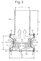
- Fig.3 is a section view of a speaker structure according to a second comparative example.
- the second example is a variation of the first example, and only the shape of cabinet covering the two speakers 20 and 30 is different from the first embodiment.
- the cabinet comprises a cylindrical hollow body 12a similar to the cabinet 10 as shown in Fig.1, and a cylindrical hollow projection part 12b projecting upward from the body 12a. The top end of the projection part 12b is open to let the air escape.
- the resonance frequency may be reduced by the opening, and thereby the ability for reproducing low frequency sound of the speaker may be improved.
- Fig.4 is a section view of a speaker structure according to an embodiment of the present invention.
- reference numeral 13 denotes a cylindrical hollow cabinet
- reference numerals 20 and 30 denote a speaker similar to the speaker of the first example.
- One end of the rib 51 is fixed at the yoke 27 of the speaker 20.
- the other end of the rib 51 is threaded, thereby being connected to the connecting unit 54 by screwing.
- one end of the rib 52 is fixed at the yoke 37 of the speaker 30, and the other end of the rib 52 is threaded, thereby being connected to the connecting unit 54 by screwing.
- One end of the rib 51 and one end of the rib 52 are fixed at yokes 27 and 37 respectively as shown in Fig.4, but may be fixed at any parts of the magnetic circuits 24 and 34 respectively.
- the speaker 20 and the speaker 30 are coupled via the rib 51, the rib 52 and the connecting unit 54.
- the ribs 51 and 52 comprises cylindrical metal, etc, and it is preferable that the ribs 51 and 52 do not have a constant cross sectional area throughout their length so that they do not resonate by themselves.
- the connecting unit 54 is fixed at a stand 60. Furthermore, it is preferable that the ribs 51 and 52 are fixed, at the magnetic circuits 24 and 34 respectively, at their symmetrically opposed center positions, and thereby it is possible to reduce the resonance of the ribs 51 and 52.
- Fig.5 is a bottom view of the cabinet 13.
- the speaker 20 is mounted at the lower part of the figure, and the speaker 30 is mounted at the upper part of the figure.
- An opening 15 for the stand 60 is provided at the bottom of the cabinet, and doors 14a and 14b are provided around the opening.
- the doors 14a and 14b are mounted on the cabinet 13 by means of hinges so as to be opened from side to side frontward in the figure. Opening the doors 14a and 14b makes mounting the stand 60 to the connecting unit 64 and wiring inside the cabinet easy.
- the entire edges of the cabinet 13 are positioned by the frames 22 and 32 of speakers, and the shock absorbers 42. And also a shock absorber 42 is placed between the doors 14a, 14b of the cabinet 13 and the stand 60. These shock absorbers 42 secure airtightness of the cabinet 10, and keep the cabinet 13 in floating state compared to the speakers 20 and 30, and also to the stand 60. As stated above, the cabinet 13 is kept in floating state compared to the speakers 20 and 30 and to the stand 60, and thereby vibrations of the speakers 20 and 30 are not transmitted to the cabinet 13 directly.
- the materials and so on of the shock absorbers 42 are similar to ones for the first embodiment aforementioned.
- a intermediate supporter 70 is provided inside the cabinet 13 to stabilize the rib 51.
- the intermediate supporter 70 comprises a ring 71, a base 72 fixed at the rib 51, columns 73 for fixing the ring 71 and the base 72, and a shock absorber 74.
- the intermediate supporter 70 is in contact with the inner wall of the cabinet 13 via the shock absorber 74.
- Fig.6 is a perspective view showing the inside of the cabinet. According to Fig.6, it can be understood how the intermediate supporter 70 is fixed at the rib. Using this intermediate supporter 70, the relative position of the rib 51 to the cabinet 13 may be kept constant, and the rib may be stabilized accordingly. Felt or the like is suitable for the material of the shock absorber 74. In addition, it is preferable to wrap a sound absorber such as glass fiber around the columns 73.
- the intermediate supporter 70 is fixed at only the rib 51 as shown in Fig.4, but a similar intermediate supporter may be provided for the rib 52.
- Signals such as audio signal are supplied to each speaker through a input terminal, a connecting wire, and terminals, as in the first embodiment, which are not shown in Fig.4. It is preferable, as in the first embodiment, that signals to be supplied to each speaker are the same signals in phase, and generate the same sound from each speaker at the same time. When the same signals in phase are supplied to each speaker, reactions of each speaker due to the vibration of the cones are canceled out through the ribs 51 and 52, and connecting unit 54.
- the rib 51 fixed at the speaker 20 is fixed to the connecting unit 54 by screwing.
- the guide 29 of the speaker 20 is engaged with a end of the cabinet 13 via the shock absorber 42.
- the speaker 30 and the rib 52 fixed at the speaker 30 are inserted from the other end of the cabinet 13 in such a way that the rib 52 is screwed into the connecting unit 54.
- the rib 52 is fixed to the connecting unit 54 by screwing in such a way that the guide 39 of the speaker 30 is engaged with the other end of the cabinet 13 via the shock absorbers 42.
- the speakers 20 and 30 are secured by the ribs 51 and 52, and the connecting unit 54, and the cabinet 13 is positioned between the guides of the speakers 20 and 30.
- the doors 14a and 14b of the cabinet are opened, and the stand 60 is inserted through the opened the doors, and then connecting unit 54 is fixed to the stand 60. Furthermore, predetermined wiring for each speaker is carried out. Lastly, the doors 14a and 14b are closed in such a way that the shock absorber 42 is positioned between the doors 14a, 14b, and the stand 60. According to the above procedures, the speaker structure of the embodiment is assembled.
- the two speakers are fixed to each other via fixing devices including ribs allowing spacing between the two speakers, and thereby it is possible that the vibration of the yoke is suppressed efficiently and the sound exchanging efficiency of the cone is increased.
- the speaker structure is so configured that it is assembled while pulling both speakers by the connecting unit 54, thereby may be steady regardless of the vibration during transportation.
Landscapes
- Health & Medical Sciences (AREA)
- Otolaryngology (AREA)
- Physics & Mathematics (AREA)
- Engineering & Computer Science (AREA)
- Acoustics & Sound (AREA)
- Signal Processing (AREA)
- Details Of Audible-Bandwidth Transducers (AREA)
- Audible-Bandwidth Dynamoelectric Transducers Other Than Pickups (AREA)
- Obtaining Desirable Characteristics In Audible-Bandwidth Transducers (AREA)
Applications Claiming Priority (2)
| Application Number | Priority Date | Filing Date | Title |
|---|---|---|---|
| JP2000177180 | 2000-06-08 | ||
| JP2000177180A JP2001352592A (ja) | 2000-06-08 | 2000-06-08 | スピーカ構造 |
Publications (3)
| Publication Number | Publication Date |
|---|---|
| EP1162864A2 EP1162864A2 (en) | 2001-12-12 |
| EP1162864A3 EP1162864A3 (en) | 2003-04-02 |
| EP1162864B1 true EP1162864B1 (en) | 2006-05-17 |
Family
ID=18678813
Family Applications (1)
| Application Number | Title | Priority Date | Filing Date |
|---|---|---|---|
| EP01304973A Expired - Lifetime EP1162864B1 (en) | 2000-06-08 | 2001-06-07 | Speaker structure |
Country Status (7)
Cited By (1)
| Publication number | Priority date | Publication date | Assignee | Title |
|---|---|---|---|---|
| CZ301578B6 (cs) * | 2005-02-25 | 2010-04-21 | Šroll@Ludek | Reproduktorová soustava vyzarující válcovou akustickou vlnu |
Families Citing this family (43)
| Publication number | Priority date | Publication date | Assignee | Title |
|---|---|---|---|---|
| JP4064160B2 (ja) * | 2002-06-07 | 2008-03-19 | 富士通テン株式会社 | スピーカ装置 |
| US7551749B2 (en) | 2002-08-23 | 2009-06-23 | Bose Corporation | Baffle vibration reducing |
| US6985593B2 (en) * | 2002-08-23 | 2006-01-10 | Bose Corporation | Baffle vibration reducing |
| JP3965366B2 (ja) | 2003-03-19 | 2007-08-29 | 富士通テン株式会社 | スピーカユニットの支持構造及びスピーカシステム |
| GB2424537B (en) | 2003-06-09 | 2007-09-12 | Fujitsu Ten Ltd | Speaker apparatus |
| GB2414620A (en) * | 2004-05-24 | 2005-11-30 | Blast Loudspeakers Ltd | Loudspeaker with opposing drivers for vibration cancelling |
| WO2006127656A2 (en) * | 2005-05-24 | 2006-11-30 | Daniel Mapes-Riordan | Loudspeaker design |
| JP2007235727A (ja) * | 2006-03-02 | 2007-09-13 | Zoruzo:Kk | スピーカー装置 |
| JP4767079B2 (ja) * | 2006-04-19 | 2011-09-07 | 鈴木 忠 | 拡声器 |
| JP4712599B2 (ja) * | 2006-04-19 | 2011-06-29 | 富士通テン株式会社 | スピーカ装置 |
| JP4126082B2 (ja) * | 2006-11-01 | 2008-07-30 | 一満 今井 | 無反動スピーカシステム及びユニット |
| US7881488B2 (en) * | 2006-11-01 | 2011-02-01 | Bose Corporation | In-plane speaker |
| JP2008042947A (ja) * | 2007-09-27 | 2008-02-21 | Time Domain:Kk | スピーカシステム |
| JP2009094677A (ja) * | 2007-10-05 | 2009-04-30 | Fujitsu Ten Ltd | スピーカ装置 |
| WO2009050909A1 (ja) * | 2007-10-19 | 2009-04-23 | Kazumichi Imai | 無反動スピーカユニット |
| JP5037386B2 (ja) * | 2008-02-27 | 2012-09-26 | シャープ株式会社 | 音響装置およびエンクロージャ |
| JP5067356B2 (ja) * | 2008-06-24 | 2012-11-07 | 譲一 斉藤 | スピーカ装置 |
| US8180076B2 (en) * | 2008-07-31 | 2012-05-15 | Bose Corporation | System and method for reducing baffle vibration |
| BRPI0816732A2 (pt) * | 2008-10-14 | 2015-03-10 | Pioneer Corp | Dispositivo de alto-falante |
| DE102009034110B3 (de) * | 2009-07-21 | 2011-01-27 | Kammler, Dietmar, Dr. | Lautsprecherbox |
| CN102172045A (zh) * | 2009-12-25 | 2011-08-31 | 日本先锋公司 | 扬声器用振动体、扬声器装置 |
| JP5719718B2 (ja) * | 2011-01-06 | 2015-05-20 | 有限会社ゾルゾ | スピーカユニット及び同ユニットを用いたスピーカシステム |
| GB2488758A (en) | 2011-03-02 | 2012-09-12 | Gp Acoustics Uk Ltd | Bass reflex loudspeaker has acoustic leakage in walls of port duct |
| GB2491108B (en) * | 2011-05-18 | 2014-06-04 | Gp Acoustics Uk Ltd | Loudspeaker |
| FR3012716B1 (fr) * | 2013-10-30 | 2016-07-01 | Devialet | Enceinte acoustique a au moins un haut-parleur a membrane mobile convexe en continuite de forme avec un organe adjacent |
| CN105025421A (zh) * | 2014-04-17 | 2015-11-04 | 有限会社左尔佐 | 扬声器 |
| JP6442201B2 (ja) * | 2014-09-08 | 2018-12-19 | 株式会社河合楽器製作所 | 電子楽器 |
| US10045461B1 (en) * | 2014-09-30 | 2018-08-07 | Apple Inc. | Electronic device with diaphragm cooling |
| JP6329891B2 (ja) * | 2014-12-22 | 2018-05-23 | 株式会社ユニバーサルエンターテインメント | 遊技機 |
| JP6329890B2 (ja) * | 2014-12-22 | 2018-05-23 | 株式会社ユニバーサルエンターテインメント | 遊技機 |
| JP2016127404A (ja) * | 2014-12-26 | 2016-07-11 | 富士通テン株式会社 | スピーカ装置および制振ユニット |
| KR102663406B1 (ko) * | 2016-04-04 | 2024-05-14 | 엘지디스플레이 주식회사 | 패널 진동형 음향 발생 액츄에이터 및 그를 포함하는 양면 표시 장치 |
| US11272284B2 (en) | 2018-02-06 | 2022-03-08 | Jeffrey P. North | Open-back linear bi-directional cabinet for speaker driver |
| FR3087067B1 (fr) * | 2018-10-08 | 2022-02-25 | Devialet | Enceinte acoustique a deux haut-parleurs tete-beche fixes sur une armature interne |
| CN109413551B (zh) * | 2018-10-31 | 2020-09-04 | 宁波音沛乐电子有限公司 | 双磁路的中音压缩驱动装置 |
| CN109348381A (zh) * | 2018-11-22 | 2019-02-15 | 深圳市美妙之音科技有限公司 | 一种水平扩散式360度气动扬声器 |
| FR3089380B1 (fr) * | 2018-12-03 | 2020-11-20 | Sagemcom Broadband Sas | Pièce de rigidification pour caisson d’enceinte acoustique |
| JP2020121604A (ja) * | 2019-01-29 | 2020-08-13 | 株式会社デンソーテン | スピーカ装置 |
| CN109951778B (zh) * | 2019-04-16 | 2020-12-01 | 陈国富 | 全频扬声器 |
| JP7420576B2 (ja) * | 2020-02-04 | 2024-01-23 | 株式会社デンソーテン | スピーカユニット |
| JP7354010B2 (ja) * | 2020-02-18 | 2023-10-02 | 株式会社デンソーテン | スピーカ装置およびスピーカユニット |
| JP7523309B2 (ja) * | 2020-10-07 | 2024-07-26 | 株式会社デンソーテン | スピーカユニットの取付構造 |
| FR3119960B1 (fr) * | 2021-02-18 | 2024-01-05 | Moca Audio | Véhicule comportant un dispositif de restitution sonore disposé dans un espace médian avant de l’habitacle, dispositif adapté |
Family Cites Families (11)
| Publication number | Priority date | Publication date | Assignee | Title |
|---|---|---|---|---|
| US1674895A (en) * | 1925-04-17 | 1928-06-26 | Richard D Fay | Method of and apparatus for radiating sound waves |
| US3393764A (en) * | 1966-12-27 | 1968-07-23 | Curtiss R. Schafer | Loudspeaker systems |
| US4083426A (en) | 1974-10-17 | 1978-04-11 | Peugh H Mark | Loud speaker apparatus |
| JPS606157B2 (ja) * | 1977-07-25 | 1985-02-15 | ソニー株式会社 | スピ−カ |
| DE3414407C2 (de) * | 1984-04-17 | 1986-02-20 | Jürgen 6804 Ilvesheim Quaas | Anordnung von Schallwandlern in einer Schallführung, insbesondere für Lautsprecherboxen |
| DK156454C (da) | 1985-01-03 | 1990-01-15 | Johan Peter Lyngdorf | Hoejttalerenhed med mere end en bas/mellemtone-hoejttaler |
| JP2531713B2 (ja) * | 1987-12-02 | 1996-09-04 | キヤノン株式会社 | 電子カメラ |
| JP3134955B2 (ja) | 1991-11-26 | 2001-02-13 | ソニー株式会社 | スピーカ装置 |
| JPH05328473A (ja) | 1992-05-27 | 1993-12-10 | Mitsubishi Electric Corp | 低音再生用スピーカシステム |
| JP2797292B2 (ja) | 1993-05-11 | 1998-09-17 | 船井電機株式会社 | テレビジョン受像機のスピーカの固定構造 |
| JP3845989B2 (ja) | 1997-11-13 | 2006-11-15 | 株式会社タイムドメイン | スピーカ |
-
2000
- 2000-06-08 JP JP2000177180A patent/JP2001352592A/ja active Pending
-
2001
- 2001-06-06 US US09/876,859 patent/US6678384B2/en not_active Expired - Lifetime
- 2001-06-06 CA CA002349752A patent/CA2349752C/en not_active Expired - Lifetime
- 2001-06-07 EP EP01304973A patent/EP1162864B1/en not_active Expired - Lifetime
- 2001-06-07 DE DE60119622T patent/DE60119622T2/de not_active Expired - Lifetime
- 2001-06-08 KR KR10-2001-0031911A patent/KR100453251B1/ko not_active Expired - Fee Related
- 2001-06-08 CN CNB011208589A patent/CN1236651C/zh not_active Expired - Lifetime
Cited By (1)
| Publication number | Priority date | Publication date | Assignee | Title |
|---|---|---|---|---|
| CZ301578B6 (cs) * | 2005-02-25 | 2010-04-21 | Šroll@Ludek | Reproduktorová soustava vyzarující válcovou akustickou vlnu |
Also Published As
| Publication number | Publication date |
|---|---|
| KR100453251B1 (ko) | 2004-10-15 |
| US20020021818A1 (en) | 2002-02-21 |
| CN1236651C (zh) | 2006-01-11 |
| EP1162864A2 (en) | 2001-12-12 |
| KR20010111033A (ko) | 2001-12-15 |
| DE60119622T2 (de) | 2006-09-21 |
| EP1162864A3 (en) | 2003-04-02 |
| JP2001352592A (ja) | 2001-12-21 |
| CN1329456A (zh) | 2002-01-02 |
| US6678384B2 (en) | 2004-01-13 |
| CA2349752C (en) | 2004-12-28 |
| CA2349752A1 (en) | 2001-12-08 |
| DE60119622D1 (de) | 2006-06-22 |
Similar Documents
| Publication | Publication Date | Title |
|---|---|---|
| EP1162864B1 (en) | Speaker structure | |
| US11102582B2 (en) | Audio transducers and devices incorporating the same | |
| CN1819710B (zh) | 反射板减振 | |
| US5815589A (en) | Push-pull transmission line loudspeaker | |
| EP0147992B1 (en) | Multi-driver loudspeaker | |
| US7292706B2 (en) | Support structure of loudspeaker unit and loudspeaker system | |
| US6925188B1 (en) | Ported speaker enclosure of a portable computer | |
| CA1168989A (en) | Loudspeaker enclosure | |
| KR20030095267A (ko) | 스피커장치 | |
| EP2200336A1 (en) | Recoilless speaker system | |
| JP2004343286A (ja) | スピーカ装置 | |
| JP2008136186A (ja) | 無反動スピーカシステム及びユニット | |
| KR100729272B1 (ko) | 1채널 2웨이 방식의 스피커 | |
| AU747905B2 (en) | Loudspeaker systems | |
| US6445803B1 (en) | Speaker | |
| US6557664B1 (en) | Loudspeaker | |
| JP3896675B2 (ja) | スピーカ装置 | |
| EP0095876B1 (en) | Multi-driver-loudspeaker | |
| JP4744416B2 (ja) | スピーカ装置 | |
| CN101686422B (zh) | 扬声器系统 | |
| JP4471127B2 (ja) | スピーカ装置 | |
| US7515724B2 (en) | Loudspeaker driver | |
| JPH11355876A (ja) | スピーカの取り付け構造 | |
| KR960003848B1 (ko) | 이중케비넷 스피커 | |
| KR20050082887A (ko) | 다점 구동형 멀티웨이 슬림 평판 스피커 시스템 |
Legal Events
| Date | Code | Title | Description |
|---|---|---|---|
| PUAI | Public reference made under article 153(3) epc to a published international application that has entered the european phase |
Free format text: ORIGINAL CODE: 0009012 |
|
| AK | Designated contracting states |
Kind code of ref document: A2 Designated state(s): AT BE CH CY DE DK ES FI FR GB GR IE IT LI LU MC NL PT SE TR |
|
| AX | Request for extension of the european patent |
Free format text: AL;LT;LV;MK;RO;SI |
|
| 17P | Request for examination filed |
Effective date: 20011211 |
|
| PUAL | Search report despatched |
Free format text: ORIGINAL CODE: 0009013 |
|
| AK | Designated contracting states |
Kind code of ref document: A3 Designated state(s): AT BE CH CY DE DK ES FI FR GB GR IE IT LI LU MC NL PT SE TR |
|
| AX | Request for extension of the european patent |
Extension state: AL LT LV MK RO SI |
|
| RIC1 | Information provided on ipc code assigned before grant |
Ipc: 7H 04R 1/28 A |
|
| 17Q | First examination report despatched |
Effective date: 20030818 |
|
| AKX | Designation fees paid |
Designated state(s): DE GB |
|
| GRAP | Despatch of communication of intention to grant a patent |
Free format text: ORIGINAL CODE: EPIDOSNIGR1 |
|
| GRAS | Grant fee paid |
Free format text: ORIGINAL CODE: EPIDOSNIGR3 |
|
| GRAA | (expected) grant |
Free format text: ORIGINAL CODE: 0009210 |
|
| AK | Designated contracting states |
Kind code of ref document: B1 Designated state(s): DE GB |
|
| REG | Reference to a national code |
Ref country code: GB Ref legal event code: FG4D |
|
| REF | Corresponds to: |
Ref document number: 60119622 Country of ref document: DE Date of ref document: 20060622 Kind code of ref document: P |
|
| PLBE | No opposition filed within time limit |
Free format text: ORIGINAL CODE: 0009261 |
|
| STAA | Information on the status of an ep patent application or granted ep patent |
Free format text: STATUS: NO OPPOSITION FILED WITHIN TIME LIMIT |
|
| 26N | No opposition filed |
Effective date: 20070220 |
|
| REG | Reference to a national code |
Ref country code: GB Ref legal event code: 732E Free format text: REGISTERED BETWEEN 20100408 AND 20100414 |
|
| PGFP | Annual fee paid to national office [announced via postgrant information from national office to epo] |
Ref country code: DE Payment date: 20200618 Year of fee payment: 20 |
|
| PGFP | Annual fee paid to national office [announced via postgrant information from national office to epo] |
Ref country code: GB Payment date: 20200625 Year of fee payment: 20 |
|
| REG | Reference to a national code |
Ref country code: DE Ref legal event code: R071 Ref document number: 60119622 Country of ref document: DE |
|
| REG | Reference to a national code |
Ref country code: GB Ref legal event code: PE20 Expiry date: 20210606 |
|
| PG25 | Lapsed in a contracting state [announced via postgrant information from national office to epo] |
Ref country code: GB Free format text: LAPSE BECAUSE OF EXPIRATION OF PROTECTION Effective date: 20210606 |