EP1161317B1 - Transportsystem - Google Patents
Transportsystem Download PDFInfo
- Publication number
- EP1161317B1 EP1161317B1 EP00914052A EP00914052A EP1161317B1 EP 1161317 B1 EP1161317 B1 EP 1161317B1 EP 00914052 A EP00914052 A EP 00914052A EP 00914052 A EP00914052 A EP 00914052A EP 1161317 B1 EP1161317 B1 EP 1161317B1
- Authority
- EP
- European Patent Office
- Prior art keywords
- swivel
- movement
- drive
- arm
- conveying
- Prior art date
- Legal status (The legal status is an assumption and is not a legal conclusion. Google has not performed a legal analysis and makes no representation as to the accuracy of the status listed.)
- Expired - Lifetime
Links
Images


Classifications
-
- B—PERFORMING OPERATIONS; TRANSPORTING
- B25—HAND TOOLS; PORTABLE POWER-DRIVEN TOOLS; MANIPULATORS
- B25J—MANIPULATORS; CHAMBERS PROVIDED WITH MANIPULATION DEVICES
- B25J9/00—Programme-controlled manipulators
- B25J9/10—Programme-controlled manipulators characterised by positioning means for manipulator elements
- B25J9/106—Programme-controlled manipulators characterised by positioning means for manipulator elements with articulated links
- B25J9/1065—Programme-controlled manipulators characterised by positioning means for manipulator elements with articulated links with parallelograms
-
- B—PERFORMING OPERATIONS; TRANSPORTING
- B21—MECHANICAL METAL-WORKING WITHOUT ESSENTIALLY REMOVING MATERIAL; PUNCHING METAL
- B21D—WORKING OR PROCESSING OF SHEET METAL OR METAL TUBES, RODS OR PROFILES WITHOUT ESSENTIALLY REMOVING MATERIAL; PUNCHING METAL
- B21D43/00—Feeding, positioning or storing devices combined with, or arranged in, or specially adapted for use in connection with, apparatus for working or processing sheet metal, metal tubes or metal profiles; Associations therewith of cutting devices
- B21D43/02—Advancing work in relation to the stroke of the die or tool
- B21D43/04—Advancing work in relation to the stroke of the die or tool by means in mechanical engagement with the work
- B21D43/05—Advancing work in relation to the stroke of the die or tool by means in mechanical engagement with the work specially adapted for multi-stage presses
-
- B—PERFORMING OPERATIONS; TRANSPORTING
- B25—HAND TOOLS; PORTABLE POWER-DRIVEN TOOLS; MANIPULATORS
- B25J—MANIPULATORS; CHAMBERS PROVIDED WITH MANIPULATION DEVICES
- B25J9/00—Programme-controlled manipulators
- B25J9/10—Programme-controlled manipulators characterised by positioning means for manipulator elements
- B25J9/106—Programme-controlled manipulators characterised by positioning means for manipulator elements with articulated links
Definitions
- the invention relates to a device for transporting of workpieces according to the preamble of claim 1.
- Step or transfer presses have one Transport device with which the workpieces from a Work station to be transported to the next.
- Such transport facilities are included Carrier rails equipped through the entire length of the Stretch forming machine. They are used to transport the parts DIN rails equipped with gripper or holding elements. A distinction is made between, depending on the movement sequence a two-axis transfer equipped with suction crossbeams or a three-axis transfer with gripper elements. As Additional movement can also be pivoted to change the position of the part may be required during the transport step.
- Transfer systems come with a number of drives equipped in operative connection with the Movement transmission means carry out the parts transport.
- the system is special as a two-axis transfer Vacuum bar, as well as a three-axis transfer with grippers convertible.
- this requires universal use a corresponding construction effort.
- each stand area is one in DE 196 544 75 A1 disclosed transfer device.
- the drive elements will be as Parallel kinematics are known are used.
- these known movement elements will not telescopic extension of the drive rods made, but with constant bar length, the articulation points changed and thus achieved the transport movements.
- the the Pivot points absorbing forces or torques are in the The distance to each other is not constant and especially when this Points close together due to the desired driving curve Support problems can occur.
- To increase the System stiffness also becomes more parallel to each other Handlebars suggested the crossbars with each other get connected.
- To achieve a functionally reliable Transporting large parts becomes the proposed one System correspondingly complex.
- the invention has for its object with simple Measures a highly flexible and precise transport system create which is independent of the respective transport situation an evenly secure support of the forces and Moments guaranteed.
- the invention is based on the idea that and direction of rotation of 2 drives to each other and in Active connection with motion transmission means any biaxial movements in horizontal and / or vertical Direction are possible.
- 2 highly dynamic drives are included through simple control processes, the sense of rotation and the speed influence, regulated. This regulation generated by Motion overlap in the X and Y axes each programmed Driving curve in one plane.
- a motion transmission means a rack or Timing belt drive used, initiating the driving curve on a swivel or transport arm via a gear wheel, this is also due to the unchangeable gear wheel diameter ensures an even torque support.
- the respective movement position does not lead to any change in the effective lever arm for torque introduction or support and thus ensures a safe and precise Parts transportation.
- the transport system can be more simple Execution or in duplicate execution as a mirror image to each other across the press transport direction in Stand area to be attached.
- the two transport systems e.g. with one carrying the parts Sucker bar connected.
- each transport device via one have their own one-sided suction bar and the Transport systems are driven independently.
- a synchronization of the parts transport device with the Press ram can be made using known electronic means such as the so-called electronic wave.
- the mounting position of the transport system is variable and can e.g. above, as well as below the parts transport level.
- Weight compensation measures e.g. by growing Cylinders, both on the actual carriage, as well on the transport arm relieve the pressure on the drives and the Motion transmission means.
- the through the constructive structure the distance between the forming stages specified by the press is determined by the narrow design of the transport system is not enlarged. On the other hand, despite this space-saving design, large Transport routes easily with low mass and large Precision.
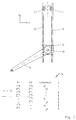
- processing stations or forming stages are one Large section press 1 shown.
- the invention Transport device 2 is arranged on the press stand 3.
- the transport system is exemplary both above and below mounted below the transport level. In simplified Different transport positions are shown recognizable. Parts are removed in forming stage 4 while in the forming stage 5, the tool upper part 6 Ram 7 moves vertically upwards after forming.
- the assigned transport system 2 is in its Park position.
- the execution of the swivel or transport arm 13 can take a variety of forms, such as in the EP 0693 334 A1 of the applicant is specified.
- FIG. 2 The movement sequences of the transport system are shown in Figure 2 seen.
- the block diagram shows 2 drives A1, A2 the gears 8, 9 in a rotational movement or in the rest position hold. These gears 8, 9 act on racks 10, 11 caused by the gear drive perform vertical movement.
- the lower part of the racks 10, 11 acts together on the Gear 12.
- This gear 12 is the transport arm 13 connected to the common center of movement 26.
- the Movements of the transport arm 13 are shown in Table 14 seen. However, only the movements that are shown in the Drive case due to the same speeds of drives A1, A2 result.
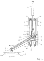
- FIG. 3 An exemplary embodiment is shown in FIG. 3.
- the drive train known from FIG. 2 is provided with the same item numbers.
- a swivel drive 15 is provided which, via parallelogram joints 16, can swivel the suction crossmember 17 attached to the end of the transport arm 13 about the central axis 18. This movement is necessary if the part 20 held by the suction cups 19 is to receive a change in position during the transport movement in the press passage direction 21. This change in position serves to enable different situations when parts are removed and parts are inserted.
- other movement transmission means such as a toothed belt drive can of course also be used.
- the swivel drive 15 can also be attached stationary, for example, between the drives A1, A2.
- the desired movements of the suction traverse 17 would then be initiated via a toothed rack on a toothed pinion in the center of movement 26. If no additional swiveling of the suction traverse 17 is provided, the swivel drive 15 can be omitted.
- a counterbalance cylinder 22 is provided to relieve the drive elements. All of that Transport arm 13 associated components are together on one Carriage 23 mounted.
- the carriage 23 is in one Linear guide system 24 guided and stored.
- In the carriage 23 there is also a storage, not shown Racks 10, 11.
- the proposed mounting form makes it possible to use carriages 23 and guide 24 in the desired rigidity and length execute without the distance between the forming stages and thus the Enlarge transport step.
- To reduce the Drive power of the drives A1, A2 and to relieve the Associated gear elements can weight balance cylinder 25 serve which is connected to carriage 23.
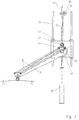
- Figure 4 shows a variant of the representation of the Figure 3 described embodiment.
- the transport or swivel arm 13 was changed which now starts from the center of movement 26 in point 27 of the parallelogram 16 attacks.
- Point 27 is preferably located halfway along the parallelogram joints 16 and also route 26 - 27 corresponds to this half route.
- This geometry lies the center of point 26 and the center of the Parallelogram cross strut 20 on a horizontal line, which also ensures a horizontal travel path or is possible.
- any driving curves feasible in the plane As already shown in principle figure 2 with the drive system, however, any driving curves feasible in the plane.
- the stroke of the carriage 23 corresponds to the lifting stroke of the respective in this arrangement Travel curve.
- the transport arm 13 acts as if Swivel drive on the carrying the suction traverse 17 Parallelogram 16.
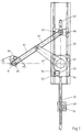
- Linear guide 29 provided in which the carriage one Performs vertical movement.
- On the carriage 30 is the upper part 31 of the parallelogram 16 articulated.
- a drive 32 can be provided by a pivotal movement that on the parallelogram 16 Suction cross member 17 is transmitted, a part pivoting allows.
- a Single lever can be used and the position of the suction traverse 17 would be connected to a rotary actuator Toothed belt drive regulated accordingly.
- Figure 5 shows an embodiment with a linear drive 40.
- a drive 34 acts on this toothed rack 33 Gear 35.
- the rack 33 is connected to a slide 36 and when the drive 34 rotates, the carriage leads 36 a vertical movement.
- a swivel unit consisting of drive 37, pinion 38 and tooth segment 39.
- Based on the desired and programmed Driving curve finds the necessary regulation of linear drive 40 and swivel drive 37 instead.
- An additional Parts can be swiveled during the transport step Swivel drive 41 by acting on the parallelogram in already explained.
- the linear drive is only an example in FIG shown and can by other commercially available components such as ball screw, linear motor, etc. are replaced.
- a lifting drive 49 is used to achieve the desired driving curves and a rotary actuator 50 in common motion superimposed Function or provided as an individually driven movement.
- the lifting drive 49 is stationary, e.g. at the Press stand, attached, which makes the accelerated Masses are reduced.
- the lifting drive 49 acts as an example via a pinion 51 on a rack 52.
- Die rack 52 transmits translatory movement to one Carriage 53.
- Carriage 53 is over guide elements 54 in Guide 55 mounted vertically.
- Pivot lever 13 is similar to the drive lever in FIG. 4 59 articulated and also those described in FIG. 4 apply preferred geometric and kinematic relationships.
- the holder for the actual workpiece clamping system e.g. Sucker bar or gripper is marked with 60. Should one Change in position of the workpiece due to different Removal and insertion positions, which is required Recording 60 pivotable about the pivot point 61.
- the swiveling is regulated via the drive 62 in operative connection with Pulley 63 and timing belt 64 with the pivot axis connected pulley 65 drives.
- the one in guides 55 vertically movable carriage 66 is used to support the Drive lever 59 and the drive 62nd
- connecting shafts starting from the respective drive pivot points, transverse to Part transport direction by 2 transport systems mechanically to couple with each other for the purpose of synchronization and / or the possibility of reducing the number of drives.
Landscapes
- Engineering & Computer Science (AREA)
- Mechanical Engineering (AREA)
- Robotics (AREA)
- Specific Conveyance Elements (AREA)
- Press Drives And Press Lines (AREA)
- Transmission Devices (AREA)
- Manipulator (AREA)
- Intermediate Stations On Conveyors (AREA)
- Threshing Machine Elements (AREA)
Description
- Figur 1
- Teilansicht einer Großteilstufenpresse mit in Ständerbereich angeordnete Transfereinrichtungen
- Figur 2
- Prinzipbild des Transportsystems mit zugeordneter Bewegungstabelle
- Figur 3
- Ausführungsbeispiel des Transportsystem
- Figur 4
- Variante von Figur 3 mit anderem Anlenkpunkt
- Figur 5
- Ein weiteres Ausführungsbeispiel mit Verzahnungsgetriebe
- Figur 6
- Ein Ausführungsbeispiel mit Zahnriementrieb
- Figur 7
- Variante von Figur 5
Der aus Figur 2 bekannte Antriebsstrang ist mit gleichen Positionsnummern versehen. Als weiterer Antrieb ist ein Schwenkantrieb 15 vorgesehen der über Parallelogrammgelenke 16 die am Ende des Transportarmes 13 befestigte Saugertraverse 17 um die Mittelachse 18 schwenken kann. Diese Bewegung ist dann erforderlich, wenn das durch die Saugnäpfe 19 gehaltene Teil 20 während der Transportbewegung in Pressendurchlaufrichtung 21 eine Lageveränderung erhalten soll. Diese Lageänderung dient dazu unterschiedliche Situationen bei Teileentnahme und Teileeinlegen zu ermöglichen. Statt einer Gelenkeinheit können natürlich auch andere Bewegungsübertragungsmittel wie z.B. ein Zahnriementrieb verwendet werden. Zur Reduzierung der bewegten Massen kann der Schwenkantrieb 15 auch stationär, z.B., zwischen den Antrieben A1, A2 angebracht werden. Die gewünschten Bewegungen der Saugertraverse 17 würden dann über eine Zahnstange auf ein Zahnritzel im Bewegungsmittelpunkt 26 eingeleitet. Ist keine zusätzliche Verschwenkung der Saugertraverse 17 vorgesehen, kann der Schwenkantrieb 15 entfallen.
- 1
- Großteilstufenpresse
- 2
- Transportsystem
- 3
- Pressenständer
- 4
- Umformstufe
- 5
- Umformstufe
- 6
- Werkzeugoberteil
- 7
- Stößel
- 8
- Zahnrad links
- 9
- Zahnrad rechts
- 10
- Zahnstange links
- 11
- Zahnstange rechts
- 12
- Zahnrad
- 13
- Transportarm
- 14
- Tabelle
- 15
- Schwenkantrieb
- 16
- Parallelogrammgelenk
- 17
- Saugertraverse
- 18
- Drehpunkt
- 19
- Saugnäpfe
- 20
- Teil
- 21
- Pressendurchlaufrichtung
- 22
- Gewichtsausgleich
- 23
- Schlitten
- 24
- Linearführungssystem
- 25
- Gewichtsausgleichzylinder
- 26
- Bewegungsmittelpunkt
- 27
- Parallelogrammpunkt
- 28
- Parallelogramm Querstrebe
- 29
- Linearführung
- 30
- Schlitten
- 31
- Parallelogramm
- 32
- Schwenkantrieb
- 33
- Zahnstange
- 34
- Antrieb
- 35
- Zahnrad
- 36
- Schlitten
- 37
- Schwenkantrieb
- 38
- Ritzel
- 39
- Zahnsegment
- 40
- Linearantrieb
- 41
- Schwenkantrieb
- 42
- Zahnriemenscheibe
- 43
- Zahnriemenscheibe
- 44
- Zahnriemen
- 45
- Zahnriemen
- 46
- Zahnriemenscheibe
- 47
- Zahnriemenscheibe
- 48
- Zahnriemenscheibe
- 49
- Hebeantrieb
- 50
- Schwenkantrieb
- 51
- Zahnritzel
- 52
- Zahnstange
- 53
- Schlitten
- 54
- Führungselemente
- 55
- Führungen
- 56
- Zahnritzel
- 57
- Zahnrad
- 59
- Antriebshebel
- 60
- Aufnahme
- 61
- Drehpunkt
- 62
- Antrieb
- 63
- Riemenscheibe
- 64
- Zahnriementrieb
- 65
- Riemenscheibe
- 66
- Schlitten
Claims (9)
- Einrichtung zum Transportieren von Werkstücken in einer Presse, Pressenstraße, Großteil-Stufenpresse, wobei eine Bearbeitungsstation (4, 5) wenigstens eine, das Werkstück transportierende unabhängige Transporteinrichtung (2) zur Durchführung einer zweiachsigen Transportbewegung auf weist, wobei die Transporteinrichtung (2) ein Antriebssystem für einen Schwenk- bzw. Transportarm (13) umfasst, welches wenigstens zwei Antriebsmotoren (A1, A2, 8, 9, 34, 37, 49, 50) besitzt, die jeweils auf ein Bewegungsübertragungsmitt (10, 11, 33, 39, 44, 45, 52, 57) einwirken und wenigstens ein Antriebsmotor stationär angeordnet ist, wobei eine Regelung der Drehrichtung und der Drehgeschwindigkeit bzw. Stillstand der Antriebsmotoren eine abgestimmte Bewegung der Bewegungsübertragungsmittel (10, 11, 33, 39, 44, 45, 52, 57) bewirken und mittels einer Bewegungsüberlagerung eine beliebige programmierbare Fahrkurve des Schwenk- bzw. Transportarms (13, 16, 58, 59) einstellbar ist, wobei der Schwenk- bzw. Transportarm (13) an einem Schlitten (23, 36, 53) mit Linearführungen (24, 54, 55) gelagert und mit einem Parallelogrammgelenkarm (16) oder Antriebshebel (59) versehen ist, dadurch gekennzeichnet, dass die Bewegungsübertragungsmittel (10, 11, 33, 39, 44, 45, 52, 57) zur Durchführung einer Längsbewegung und insbesondere einer Hub- bzw. Senkbewegung eines Lagerschlittens (23, 36, 53) für den Schwenk- bzw. Transportarm (13, 16, 59) als Zahnrad/Zahnstangenantrieb (8-12, 33, 35, 38, 39, 51, 52, 56, 57) und/oder als Zahnrad/Zahnriemenantrieb (12, 42-48) ausgebildet ist.
- Einrichtung nach Ansprüch 1, dadurch gekennzeichnet, dass eine Längsbewegung und insbesondere eine Hub- bzw. Senkbewegung des Lagerschlittens (23) für den Schwenk- bzw. Transportarm (13) mittels zwei parallel angeordneten Zahnstangen (10, 11) erfolgt, die von den stationären Antriebsmotoren (A1, A2) über Zahnräder (8, 9) antreibbar sind.
- Einrichtung nach einem der vorhergehenden Ansprüche, dadurch gekennzeichnet, dass zwei parallel angeordnete Zahnstangen (10, 11) gemeinsam auf ein Antriebszahnrad (12) für den Schwenk- bzw. Transportarm (13) einwirken, derart, dass eine Hub- bzw. Senkbewegung eines Tragschlittens (23) und/oder eine Drehbewegung eines an dem Tragschlitten (23) gelagerten Schwenk- bzw. Transportarms (13) einstellbar ist.
- Einrichtung nach einem der vorhergehenden Ansprüche, dadurch gekennzeichnet, dass der Schwenk- bzw. Transportarm (13) ein Parallelogrammgelenk (16) umfasst, welches vorzugsweise endseitig eine vorzugsweise schwenkbare Saugertraverse (17) zur Werkstückhalterung aufweist.
- Einrichtung nach einem der vorhergehenden Ansprüche, dadurch gekennzeichnet, dass die Schwenkbewegung des Schwenk- bzw. Transportarms (13) auf einen Parallelogrammgelenkarm (16) übertragbar ist, welches seinerseits endseitig einen Führungsschlitten (30) in einer vertikalen Lihearführung (29) aufweist und welches gegenüberliegend zum Führungsschlitten (30) eine Saugertraverse (17) für eine Teilaufnahme trägt, wobei der Schwenk- bzw. Transportarm (13) vorzugsweise mittig am Parallelogrammgelenkarm (16) angelenkt ist und wobei vorzugsweise die Länge des Transportarms (13) etwa die halbe Länge des Gelenkarms (16) aufweist.
- Einrichtung nach Anspruch 1, dadurch gekennzeichnet, dass dem Parallelogrammgelenkarm (16) oder Antriebshebel (59) ein Verstellantrieb (15, 32, 62-65) als Schwenkantrieb für die Saugertraverse (17) zugeordnet ist.
- Einrichtung nach einem der vorherigen Ansprüche, dadurch gekennzeichnet, dass die Hub- bzw. Senkbewegung des Lagerschlittens (23, 36) für den Schwenk- bzw. Transportarm (13) und/oder die Verstellbewegung des Parallelogrammgelenkarms (13, 16) mittels wenigstens eines Gewichtsausgleichszylinders (22, 25) unterstützt ist.
- Einrichtung nach einem der vorhergehenden Ansprüche 1 bis 7, dadurch gekennzeichnet, dass die Bewegung des Lagerschlittens (36, 53) für den Schwenk- bzw. Transportarm (13) mittels eines Zahnrad/Zahnstangenantrieb (33-35, 49, 51, 52) erfolgt, wobei die Schwenkbewegung des Schwenk- bzw. Transportarms (13) mittels eines separaten Schwenkantriebs (37-39, 50, 56, 57) erfolgt.
- Einrichtung nach einem der Ansprüche 1 bis 8, dadurch gekennzeichnet, dass zwei parallel angeordnete Zahnriementriebe (42-48) gemeinsam auf ein Antriebszahnrad (12) für den Schwenk- bzw. Transportarm (13) einwirken, derart, dass eine Hub- bzw. Senkbewegung eines Tragschlittens (23) und/oder eine Drehbewegung eines an dem Tragschlitten (23) gelagerten Schwenk- bzw. Transportarms (13) einstellbar ist.
Applications Claiming Priority (3)
| Application Number | Priority Date | Filing Date | Title |
|---|---|---|---|
| DE19911796 | 1999-03-17 | ||
| DE19911796 | 1999-03-17 | ||
| PCT/DE2000/000651 WO2000054904A1 (de) | 1999-03-17 | 2000-03-02 | Transportsystem |
Publications (2)
| Publication Number | Publication Date |
|---|---|
| EP1161317A1 EP1161317A1 (de) | 2001-12-12 |
| EP1161317B1 true EP1161317B1 (de) | 2003-01-15 |
Family
ID=7901231
Family Applications (1)
| Application Number | Title | Priority Date | Filing Date |
|---|---|---|---|
| EP00914052A Expired - Lifetime EP1161317B1 (de) | 1999-03-17 | 2000-03-02 | Transportsystem |
Country Status (8)
| Country | Link |
|---|---|
| US (1) | US6715981B1 (de) |
| EP (1) | EP1161317B1 (de) |
| CN (1) | CN1224475C (de) |
| AT (1) | ATE231040T1 (de) |
| CA (1) | CA2361920C (de) |
| DE (2) | DE50001099D1 (de) |
| ES (1) | ES2190955T3 (de) |
| WO (1) | WO2000054904A1 (de) |
Cited By (2)
| Publication number | Priority date | Publication date | Assignee | Title |
|---|---|---|---|---|
| WO2005046907A1 (de) * | 2003-11-13 | 2005-05-26 | Müller Weingarten AG | Gelenkarmtransportvorrichtung |
| DE102020112613B3 (de) | 2020-05-11 | 2021-08-19 | Aida Europe Gmbh | Transfersystem für Pressen und Pressenanordnung |
Families Citing this family (40)
| Publication number | Priority date | Publication date | Assignee | Title |
|---|---|---|---|---|
| DE10064930A1 (de) | 2000-02-10 | 2001-08-16 | Mueller Weingarten Maschf | Horizontales Transportsystem |
| DE10042991A1 (de) | 2000-09-01 | 2002-03-21 | Mueller Weingarten Maschf | Gelenkarm-Transportsystem |
| DE10117191B4 (de) * | 2001-04-05 | 2006-01-26 | Müller Weingarten AG | Vorrichtung zum Transport von Formteilen |
| DE10234072B4 (de) * | 2002-07-26 | 2005-03-31 | Müller Weingarten AG | Stufenlose Verriegelungsvorrichtung für Werkstücktransportsysteme in Pressen |
| DE10310925B3 (de) * | 2003-03-13 | 2004-11-04 | Müller Weingarten AG | Sicherheitsvorrichtung für das Werkstücktransportsystem in einer Presse |
| TW200505606A (en) * | 2003-05-20 | 2005-02-16 | Ishikawajima Harima Heavy Ind | Panel transporting device |
| DE10328447B4 (de) * | 2003-06-25 | 2006-06-08 | Schuler Pressen Gmbh & Co. Kg | Transferpresse mit verbesserter Raumausnutzung |
| JP4557683B2 (ja) * | 2003-12-26 | 2010-10-06 | 株式会社大気社 | 搬送設備 |
| US7316149B2 (en) * | 2004-01-30 | 2008-01-08 | Komatsu Ltd. | Inter-pressing-machine work transfer device |
| DE102004015739B4 (de) * | 2004-03-29 | 2006-04-13 | Müller Weingarten AG | Transportvorrichtung |
| US7562765B2 (en) * | 2004-05-10 | 2009-07-21 | Ihi Corporation | Panel carrying device |
| ES2220234B1 (es) * | 2004-06-07 | 2005-12-01 | Fagor, S.Coop. | Dispositivo de transporte de piezas. |
| US7624614B2 (en) | 2004-11-25 | 2009-12-01 | Gudel Group Ag | Conveyor for transporting work pieces in a press |
| ES2273565B1 (es) * | 2005-03-30 | 2007-12-16 | Fagor S. Coop. | Sistema de transporte para transferir piezas entre estaciones. |
| ITMI20050682A1 (it) * | 2005-04-18 | 2006-10-19 | Cama 1 Spa | Robot a fulcri mobili |
| DE102005048391B3 (de) * | 2005-10-10 | 2007-04-05 | Siemens Ag | Stativ für ein Bestrahlungstherapiegerät sowie eine dieses Stativ aufweisende Bestrahlungseinrichtung |
| DE102006003522A1 (de) * | 2006-01-24 | 2007-08-02 | Müller Weingarten AG | Transfersystem mit Wendevorrichtung |
| DE102006045107B4 (de) * | 2006-09-21 | 2015-03-12 | Optima Nonwovens Gmbh | Reversierende Vorschubeinrichtung zum taktweisen linearen Vorschieben von Gutstapeln über eine Transportstrecke |
| JP5283930B2 (ja) * | 2008-03-05 | 2013-09-04 | 本田技研工業株式会社 | 搬送装置 |
| CN101433936B (zh) * | 2008-12-19 | 2011-07-13 | 奇瑞汽车股份有限公司 | 机械手冲压自动化生产传输翻转台 |
| DE102009043405B3 (de) * | 2009-09-29 | 2011-04-07 | Kuka Roboter Gmbh | Industrieroboter mit einem Gewichtsausgleichssystem |
| US8973768B1 (en) * | 2009-10-09 | 2015-03-10 | Par Systems, Inc. | Gantry robot system |
| DE102009060253A1 (de) * | 2009-12-23 | 2011-06-30 | SMS Siemag AG, 40237 | Doppelbesäumschere |
| DK2692486T3 (en) | 2011-03-30 | 2016-06-06 | Squse Inc | Scott-Russel mechanism arrangement |
| CN102284645B (zh) * | 2011-06-15 | 2013-07-17 | 山东潍坊福田模具有限责任公司 | 自动化线压合模工件传送及定位装置 |
| CN102295162B (zh) * | 2011-08-17 | 2013-06-12 | 苏州工业园区惠颖精密科技有限公司 | 移载装置 |
| GB2496162A (en) * | 2011-11-03 | 2013-05-08 | Vestas Wind Sys As | Datum transfer apparatus for work piece |
| CN102896251B (zh) * | 2012-10-24 | 2015-01-21 | 厦门锻压机床有限公司 | 一种工件的夹持翻转机构 |
| CN103406895B (zh) * | 2012-12-06 | 2015-10-21 | 中国第一重型机械股份公司 | 混联构型横杆式上下料机械手 |
| WO2015021564A1 (de) * | 2013-08-16 | 2015-02-19 | Güdel Group AG | Transfervorrichtung für ein werkstück |
| DE102014102522B3 (de) * | 2014-02-26 | 2015-07-09 | Schuler Pressen Gmbh | Transport- und Orientierungssystem zum Transportieren und Orientieren von Werkstücken |
| CH712403A1 (de) | 2016-04-28 | 2017-10-31 | Hatebur Umformmaschinen Ag | Transportverfahren zum Umsetzen von Werkstücken zwischen mehreren aufeinanderfolgenden Stufen einer Bearbeitungseinrichtung. |
| CH712401A1 (de) | 2016-04-28 | 2017-10-31 | Hatebur Umformmaschinen Ag | Transportvorrichtung zum Umsetzen von Werkstücken in einer mindestens zwei Stufen umfassenden Bearbeitungseinrichtung. |
| JP2018001250A (ja) * | 2016-07-06 | 2018-01-11 | アイダエンジニアリング株式会社 | ワーク搬送装置 |
| JP6266704B2 (ja) * | 2016-07-06 | 2018-01-24 | アイダエンジニアリング株式会社 | ワーク搬送装置 |
| JP6768454B2 (ja) * | 2016-11-08 | 2020-10-14 | コマツ産機株式会社 | ワーク搬送装置 |
| CN106584445B (zh) * | 2016-12-16 | 2018-12-25 | 微创(上海)医疗机器人有限公司 | 不动点机构 |
| JP6866171B2 (ja) * | 2017-01-30 | 2021-04-28 | コマツ産機株式会社 | ワーク搬送装置 |
| JP6960761B2 (ja) * | 2017-04-26 | 2021-11-05 | 株式会社Ihi物流産業システム | 搬送装置 |
| US11760573B2 (en) * | 2021-02-03 | 2023-09-19 | Everseen Limited | Bidirectional unilinear multi-carrier repository interface system |
Family Cites Families (8)
| Publication number | Priority date | Publication date | Assignee | Title |
|---|---|---|---|---|
| DE3040400C1 (de) * | 1980-10-25 | 1982-02-18 | Maschinenfabrik Weingarten Ag, 7987 Weingarten | Be- und/oder Entladegeraet fuer Pressen,Stanzen o.dgl. Werkzeugmaschinen |
| DE3040655C2 (de) * | 1980-10-29 | 1984-03-29 | Maschinenfabrik Müller-Weingarten AG, 7987 Weingarten | Be- und/oder Entladegerät für Pressen, Stanzen o.dgl. Werkzeugmaschinen |
| SE452753B (sv) | 1983-05-31 | 1987-12-14 | Komatsu Mfg Co Ltd | Anordning for lastning och/eller urlastning av arbetsstycken i och/eller fran en press eller liknande bearbetningsmaskin |
| US5452981A (en) | 1991-03-06 | 1995-09-26 | Leland D. Blatt | Automatic tool changer |
| US5222854A (en) * | 1991-09-09 | 1993-06-29 | Leland D. Blatt | Automatic tool changer |
| IT1272084B (it) | 1993-12-17 | 1997-06-11 | Comau Spa | Robot industriale, particolarmente per la movimentazione di pezzi da una pressa all'altra in una linea di presse |
| DE4408449A1 (de) | 1994-03-12 | 1995-09-14 | Mueller Weingarten Maschf | Transportsystem |
| US5842370A (en) | 1996-12-19 | 1998-12-01 | Schuler Pressen Gmbh & Co. | Transfer device and multistation presses |
-
2000
- 2000-03-02 DE DE50001099T patent/DE50001099D1/de not_active Expired - Lifetime
- 2000-03-02 AT AT00914052T patent/ATE231040T1/de not_active IP Right Cessation
- 2000-03-02 CA CA002361920A patent/CA2361920C/en not_active Expired - Fee Related
- 2000-03-02 DE DE10010079A patent/DE10010079A1/de not_active Withdrawn
- 2000-03-02 US US09/936,327 patent/US6715981B1/en not_active Expired - Fee Related
- 2000-03-02 CN CNB008050686A patent/CN1224475C/zh not_active Expired - Fee Related
- 2000-03-02 WO PCT/DE2000/000651 patent/WO2000054904A1/de active IP Right Grant
- 2000-03-02 EP EP00914052A patent/EP1161317B1/de not_active Expired - Lifetime
- 2000-03-02 ES ES00914052T patent/ES2190955T3/es not_active Expired - Lifetime
Cited By (3)
| Publication number | Priority date | Publication date | Assignee | Title |
|---|---|---|---|---|
| WO2005046907A1 (de) * | 2003-11-13 | 2005-05-26 | Müller Weingarten AG | Gelenkarmtransportvorrichtung |
| DE102020112613B3 (de) | 2020-05-11 | 2021-08-19 | Aida Europe Gmbh | Transfersystem für Pressen und Pressenanordnung |
| WO2021228326A1 (de) | 2020-05-11 | 2021-11-18 | Aida Europe Gmbh | Transfersystem für pressen und pressenanordnung |
Also Published As
| Publication number | Publication date |
|---|---|
| EP1161317A1 (de) | 2001-12-12 |
| DE50001099D1 (de) | 2003-02-20 |
| CA2361920A1 (en) | 2000-09-21 |
| CA2361920C (en) | 2005-12-06 |
| CN1354701A (zh) | 2002-06-19 |
| DE10010079A1 (de) | 2000-09-21 |
| CN1224475C (zh) | 2005-10-26 |
| ATE231040T1 (de) | 2003-02-15 |
| ES2190955T3 (es) | 2003-09-01 |
| US6715981B1 (en) | 2004-04-06 |
| WO2000054904A1 (de) | 2000-09-21 |
Similar Documents
| Publication | Publication Date | Title |
|---|---|---|
| EP1161317B1 (de) | Transportsystem | |
| EP1313575B1 (de) | Gelenkarm-transportsystem | |
| EP0850709B1 (de) | Transfereinrichtung und Mehrstationenpresse | |
| EP0672480B1 (de) | Transportsystem | |
| EP0388610B1 (de) | Pressen-Anlage mit mehreren Pressen zum Bearbeiten von Blechteilen | |
| EP1129800B1 (de) | Flexible Transporteinrichtung für Pressen | |
| EP0671228B1 (de) | Transporteinrichtung für Werkstücke in einer Presse | |
| EP0693334B1 (de) | Transportsystem | |
| DE102004006085B4 (de) | Transportvorrichtung für Werkstücke durch Pressenanlagen | |
| EP0685276B1 (de) | Umsetzvorrichtung in einer Umformmaschine, insbesondere einer Transferpresse | |
| DE19628556A1 (de) | Vorrichtung zur Entnahme und Zuführung von Formteilen | |
| EP0850710A1 (de) | Flexibler Mehrachstransfer | |
| EP1682289B1 (de) | Gelenkarmtransportvorrichtung | |
| EP1000681B1 (de) | Transfereinrichtung mit kombiniertem Antrieb | |
| EP1123761B1 (de) | Horizontales Transportsystem | |
| DE102004051977B4 (de) | Vorrichtung zum Transport und zur Lageveränderung von Werkstücken | |
| DE102015121884A1 (de) | Transportvorrichtung zum Transport eines Werkstückes entlang aufeinanderfolgender Bearbeitungsstationen einer Produktionseinrichtung, Produktionseinrichtung, mehrstufige Umformpresse und Verfahren zum Fertigen von Produkten aus Werkstücken mittels einer Produktionseinrichtung | |
| DE19851743A1 (de) | Positioniereinrichtung mit Gewichtsausgleich | |
| EP1000680B1 (de) | Modulare Transfereinrichtung mit Schwenk- und Linearantrieben | |
| DE4320430C2 (de) | Transferpressenkomplex | |
| DE10310941B4 (de) | Einrichtung zum Transport von Werkstücken | |
| DE10348643B3 (de) | Einrichtung zum Transport von Werkstücken |
Legal Events
| Date | Code | Title | Description |
|---|---|---|---|
| PUAI | Public reference made under article 153(3) epc to a published international application that has entered the european phase |
Free format text: ORIGINAL CODE: 0009012 |
|
| 17P | Request for examination filed |
Effective date: 20010823 |
|
| AK | Designated contracting states |
Kind code of ref document: A1 Designated state(s): AT BE CH CY DE DK ES FI FR GB GR IE IT LI LU MC NL PT SE |
|
| 17Q | First examination report despatched |
Effective date: 20020225 |
|
| GRAH | Despatch of communication of intention to grant a patent |
Free format text: ORIGINAL CODE: EPIDOS IGRA |
|
| GRAH | Despatch of communication of intention to grant a patent |
Free format text: ORIGINAL CODE: EPIDOS IGRA |
|
| GRAA | (expected) grant |
Free format text: ORIGINAL CODE: 0009210 |
|
| AK | Designated contracting states |
Kind code of ref document: B1 Designated state(s): AT BE CH CY DE DK ES FI FR GB GR IE IT LI LU MC NL PT SE |
|
| PG25 | Lapsed in a contracting state [announced via postgrant information from national office to epo] |
Ref country code: FI Free format text: LAPSE BECAUSE OF FAILURE TO SUBMIT A TRANSLATION OF THE DESCRIPTION OR TO PAY THE FEE WITHIN THE PRESCRIBED TIME-LIMIT Effective date: 20030115 Ref country code: IE Free format text: LAPSE BECAUSE OF FAILURE TO SUBMIT A TRANSLATION OF THE DESCRIPTION OR TO PAY THE FEE WITHIN THE PRESCRIBED TIME-LIMIT Effective date: 20030115 Ref country code: GR Free format text: LAPSE BECAUSE OF FAILURE TO SUBMIT A TRANSLATION OF THE DESCRIPTION OR TO PAY THE FEE WITHIN THE PRESCRIBED TIME-LIMIT Effective date: 20030115 |
|
| REG | Reference to a national code |
Ref country code: CH Ref legal event code: EP Ref country code: GB Ref legal event code: FG4D Free format text: NOT ENGLISH |
|
| GBT | Gb: translation of ep patent filed (gb section 77(6)(a)/1977) |
Effective date: 20030115 |
|
| REG | Reference to a national code |
Ref country code: IE Ref legal event code: FG4D Free format text: GERMAN |
|
| REF | Corresponds to: |
Ref document number: 50001099 Country of ref document: DE Date of ref document: 20030220 Kind code of ref document: P |
|
| PG25 | Lapsed in a contracting state [announced via postgrant information from national office to epo] |
Ref country code: LU Free format text: LAPSE BECAUSE OF NON-PAYMENT OF DUE FEES Effective date: 20030302 Ref country code: AT Free format text: LAPSE BECAUSE OF NON-PAYMENT OF DUE FEES Effective date: 20030302 Ref country code: CY Free format text: LAPSE BECAUSE OF FAILURE TO SUBMIT A TRANSLATION OF THE DESCRIPTION OR TO PAY THE FEE WITHIN THE PRESCRIBED TIME-LIMIT Effective date: 20030302 |
|
| PG25 | Lapsed in a contracting state [announced via postgrant information from national office to epo] |
Ref country code: MC Free format text: LAPSE BECAUSE OF NON-PAYMENT OF DUE FEES Effective date: 20030331 Ref country code: BE Free format text: LAPSE BECAUSE OF NON-PAYMENT OF DUE FEES Effective date: 20030331 |
|
| PG25 | Lapsed in a contracting state [announced via postgrant information from national office to epo] |
Ref country code: PT Free format text: LAPSE BECAUSE OF FAILURE TO SUBMIT A TRANSLATION OF THE DESCRIPTION OR TO PAY THE FEE WITHIN THE PRESCRIBED TIME-LIMIT Effective date: 20030415 Ref country code: DK Free format text: LAPSE BECAUSE OF FAILURE TO SUBMIT A TRANSLATION OF THE DESCRIPTION OR TO PAY THE FEE WITHIN THE PRESCRIBED TIME-LIMIT Effective date: 20030415 |
|
| REG | Reference to a national code |
Ref country code: SE Ref legal event code: TRGR |
|
| ET | Fr: translation filed | ||
| REG | Reference to a national code |
Ref country code: IE Ref legal event code: FD4D Ref document number: 1161317E Country of ref document: IE |
|
| REG | Reference to a national code |
Ref country code: ES Ref legal event code: FG2A Ref document number: 2190955 Country of ref document: ES Kind code of ref document: T3 |
|
| BERE | Be: lapsed |
Owner name: *MULLER WEINGARTEN A.G. Effective date: 20030331 |
|
| PLBE | No opposition filed within time limit |
Free format text: ORIGINAL CODE: 0009261 |
|
| STAA | Information on the status of an ep patent application or granted ep patent |
Free format text: STATUS: NO OPPOSITION FILED WITHIN TIME LIMIT |
|
| 26N | No opposition filed |
Effective date: 20031016 |
|
| PG25 | Lapsed in a contracting state [announced via postgrant information from national office to epo] |
Ref country code: LI Free format text: LAPSE BECAUSE OF NON-PAYMENT OF DUE FEES Effective date: 20040331 Ref country code: CH Free format text: LAPSE BECAUSE OF NON-PAYMENT OF DUE FEES Effective date: 20040331 |
|
| REG | Reference to a national code |
Ref country code: CH Ref legal event code: PL |
|
| PGFP | Annual fee paid to national office [announced via postgrant information from national office to epo] |
Ref country code: FR Payment date: 20100331 Year of fee payment: 11 |
|
| PGFP | Annual fee paid to national office [announced via postgrant information from national office to epo] |
Ref country code: GB Payment date: 20100324 Year of fee payment: 11 |
|
| PGFP | Annual fee paid to national office [announced via postgrant information from national office to epo] |
Ref country code: NL Payment date: 20100324 Year of fee payment: 11 |
|
| PGFP | Annual fee paid to national office [announced via postgrant information from national office to epo] |
Ref country code: SE Payment date: 20100324 Year of fee payment: 11 |
|
| REG | Reference to a national code |
Ref country code: NL Ref legal event code: V1 Effective date: 20111001 |
|
| REG | Reference to a national code |
Ref country code: SE Ref legal event code: EUG |
|
| GBPC | Gb: european patent ceased through non-payment of renewal fee |
Effective date: 20110302 |
|
| REG | Reference to a national code |
Ref country code: FR Ref legal event code: ST Effective date: 20111130 |
|
| PG25 | Lapsed in a contracting state [announced via postgrant information from national office to epo] |
Ref country code: FR Free format text: LAPSE BECAUSE OF NON-PAYMENT OF DUE FEES Effective date: 20110331 Ref country code: NL Free format text: LAPSE BECAUSE OF NON-PAYMENT OF DUE FEES Effective date: 20111001 |
|
| PG25 | Lapsed in a contracting state [announced via postgrant information from national office to epo] |
Ref country code: GB Free format text: LAPSE BECAUSE OF NON-PAYMENT OF DUE FEES Effective date: 20110302 |
|
| PG25 | Lapsed in a contracting state [announced via postgrant information from national office to epo] |
Ref country code: SE Free format text: LAPSE BECAUSE OF NON-PAYMENT OF DUE FEES Effective date: 20110303 |
|
| PGFP | Annual fee paid to national office [announced via postgrant information from national office to epo] |
Ref country code: ES Payment date: 20160322 Year of fee payment: 17 Ref country code: DE Payment date: 20160216 Year of fee payment: 17 |
|
| PGFP | Annual fee paid to national office [announced via postgrant information from national office to epo] |
Ref country code: IT Payment date: 20160318 Year of fee payment: 17 |
|
| REG | Reference to a national code |
Ref country code: DE Ref legal event code: R039 Ref document number: 50001099 Country of ref document: DE Ref country code: DE Ref legal event code: R008 Ref document number: 50001099 Country of ref document: DE |
|
| REG | Reference to a national code |
Ref country code: DE Ref legal event code: R231 Ref document number: 50001099 Country of ref document: DE |
|
| PG25 | Lapsed in a contracting state [announced via postgrant information from national office to epo] |
Ref country code: DE Free format text: LAPSE BECAUSE OF THE APPLICANT RENOUNCES Effective date: 20170317 |
|
| PG25 | Lapsed in a contracting state [announced via postgrant information from national office to epo] |
Ref country code: IT Free format text: LAPSE BECAUSE OF NON-PAYMENT OF DUE FEES Effective date: 20170302 |
|
| REG | Reference to a national code |
Ref country code: ES Ref legal event code: FD2A Effective date: 20180626 |
|
| PG25 | Lapsed in a contracting state [announced via postgrant information from national office to epo] |
Ref country code: ES Free format text: LAPSE BECAUSE OF NON-PAYMENT OF DUE FEES Effective date: 20170303 |