EP1158309A2 - Verfahren und Vorrichtung zur Positionserfassung - Google Patents
Verfahren und Vorrichtung zur Positionserfassung Download PDFInfo
- Publication number
- EP1158309A2 EP1158309A2 EP01112618A EP01112618A EP1158309A2 EP 1158309 A2 EP1158309 A2 EP 1158309A2 EP 01112618 A EP01112618 A EP 01112618A EP 01112618 A EP01112618 A EP 01112618A EP 1158309 A2 EP1158309 A2 EP 1158309A2
- Authority
- EP
- European Patent Office
- Prior art keywords
- image
- characteristic point
- position detection
- characteristic
- characteristic points
- Prior art date
- Legal status (The legal status is an assumption and is not a legal conclusion. Google has not performed a legal analysis and makes no representation as to the accuracy of the status listed.)
- Granted
Links
Images


Classifications
-
- G—PHYSICS
- G01—MEASURING; TESTING
- G01S—RADIO DIRECTION-FINDING; RADIO NAVIGATION; DETERMINING DISTANCE OR VELOCITY BY USE OF RADIO WAVES; LOCATING OR PRESENCE-DETECTING BY USE OF THE REFLECTION OR RERADIATION OF RADIO WAVES; ANALOGOUS ARRANGEMENTS USING OTHER WAVES
- G01S5/00—Position-fixing by co-ordinating two or more direction or position line determinations; Position-fixing by co-ordinating two or more distance determinations
- G01S5/16—Position-fixing by co-ordinating two or more direction or position line determinations; Position-fixing by co-ordinating two or more distance determinations using electromagnetic waves other than radio waves
-
- G—PHYSICS
- G01—MEASURING; TESTING
- G01S—RADIO DIRECTION-FINDING; RADIO NAVIGATION; DETERMINING DISTANCE OR VELOCITY BY USE OF RADIO WAVES; LOCATING OR PRESENCE-DETECTING BY USE OF THE REFLECTION OR RERADIATION OF RADIO WAVES; ANALOGOUS ARRANGEMENTS USING OTHER WAVES
- G01S11/00—Systems for determining distance or velocity not using reflection or reradiation
- G01S11/12—Systems for determining distance or velocity not using reflection or reradiation using electromagnetic waves other than radio waves
Definitions
- the present invention relates to a position detection apparatus, position detection method and position detection program that detect self-position of a moving object during movement of a robot, automobile or other moving object using a distance image.
- the present invention relates to self-position detection by a humanoid robot that moves by the use of legs.
- Vehicle position detection of the prior art involved receiving information emitted from a GPS or beacon, analyzing that information and then detecting the position of the vehicle. Since position detection using a GPS or beacon requires that electromagnetic waves emitted by the GPS or beacon be received, in the case of an object being present that obstructs electromagnetic waves between the electromagnetic device transmission apparatus and the reception apparatus installed in the vehicle, there is the problem of it no longer being possible to detect vehicle position. This type of system cannot be used at all by robots and so forth that move only indoors. Consequently, there are position detection apparatuses that detect the position of a vehicle based on sensor output values, or depending on the case, by matching road map data, by installing a distance sensor and azimuth sensor that detect wheel rotating speed on a vehicle. An example of this technology is described in Japanese Unexamined Patent Application, First Publication No. 9-243389.
- this position detection apparatus contains error in the output values of the distance sensor and azimuth sensor, if position detection according to the output values of the distance sensor and azimuth sensor alone continues for a long period of time, the detection error ends up accumulating resulting in the problem of the detected vehicle position differing greatly from actual vehicle position.
- the position detection apparatus of the prior art has the problem of encountering difficulty in autonomous movement since it is difficult to determine relative positional relationships with the surrounding environment.
- the object of the present invention is to provide a position detection apparatus, position detection method and position detection program that makes it possible to easily detect self-position using images of the surrounding environment during autonomous movement by a humanoid robot that moves by the use of legs or automobile.
- the invention according to a first aspect is a position detection apparatus that detects the position of a moving object, said position detection apparatus being provided with an image acquisition device that acquires an image of the forward field of view of said moving object, a distance image acquisition device having the same field of view as said image acquisition device that acquires a distance image simultaneous to acquisition of an image by said image acquisition device, a characteristic point extraction device that extracts respective characteristic points from the images of at least two consecutive frames, and a reference characteristic point selection device that calculates the amount of displacement of a position between two frames of a characteristic point extracted by said characteristic point extraction device based on said distance image, and selects a reference characteristic point for calculating self-position according to said amount of displacement.
- the displacement of this stationary object is determined, and the amount of self-movement is determined from the amount of this displacement, the effect is obtained in which self-position can be detected with high accuracy.
- extraction of the stationary object is performed autonomously, it is not necessary to provide a map and so forth in which the positions of stationary objects are pre-defined, thereby allowing the constitution to be simplified.
- road map data or other map data in addition to being able to simplify the constitution, it becomes possible to move to unknown locations, thereby obtaining the effect of being able to eliminate limitations on the range of action of the moving body.
- the invention according to a second aspect is a position detection apparatus that detects the position of a moving object, said position detection apparatus being provided with an image acquisition device that acquires an image within the forward field of view of said moving object, a reference point determination device that determines a reference characteristic point to serve as a reference during movement of said moving object based on an image obtained from said image acquisition device, and a position detection device that detects position by substituting self-movement control and the observed amount of said reference point into an extended Kalman filter.
- a position detection device that detects self-position by substituting self-movement control and the observed amount of said reference point into an extended Kalman filter, the effect is obtained in which self-position can be detected more accurately.
- the invention according to a third aspect is a position detection apparatus that detects the position of a moving object, said position detection apparatus being provided with an image acquisition device that acquires an image of the forward field of view of said moving object, a distance image acquisition device having the same field of view as said image acquisition device that acquires a distance image simultaneous to acquisition of an image by said image acquisition device, a characteristic point extraction device that extracts respective characteristic points from obtained images, and a reference characteristic point selection device that compares pre-stored object information with extracted characteristic points, and considers those characteristic points having a high correlation to be known characteristic points that are used as reference characteristic points for calculating position.
- said characteristic point selection device updates said object information by determining the relative relationship between unknown characteristic points and known characteristic points in an image in which characteristic points considered to be known are present, and storing said unknown characteristic points as known characteristic points.
- said object information is updated by determining the relative relationship between unknown characteristic points and known characteristic points in an image in which characteristic points considered to be known are present, and storing said unknown characteristic points as known characteristic points, the effect is obtained in which object information can be updated automatically.
- the invention according to a fifth aspect is a position detection apparatus that detects the position of a moving object, said position detection apparatus being provided with an image acquisition device that acquires an image of the forward field of view of said moving object, a characteristic point group extraction device that extracts a characteristic point group in said image, and a position detection device that calculates position by correlating and storing multiple characteristic point groups in an image pre-obtained with said image acquisition device with positions at which said characteristic point groups are obtained, and calculating the correlation between a characteristic point group of a newly obtained image and pre-stored characteristic point groups.
- self-position is calculated by storing multiple characteristic point groups in an image pre-obtained with said image acquisition device with positions at which said characteristic point groups are obtained, and calculating the correlation between a characteristic point group of a newly obtained image and pre-stored characteristic point groups, the effect is obtained in which, even in cases in which robot position cannot be obtained geometrically, self-position can be detected based on previous results of position detection.
- the invention according to a sixth aspect is a position detection method that detects the position of a moving object, said position detection method having an image acquisition process in which an image of the forward field of view of said moving object is acquired, a distance image acquisition process having the same field of view as said image in which a distance image is acquired simultaneous to acquisition of said image, a characteristic point extraction process in which respective characteristic points are acquired from the images of at least two consecutive frames, and a reference characteristic point selection process in which the amount of displacement of a position between two frames of a characteristic point extracted in said characteristic point extraction process is calculated based on said distance image, and a reference characteristic point for calculating position according to said amount of displacement is selected.
- the displacement of this stationary object is determined, and the amount of self-movement is determined from the amount of this displacement, the effect is obtained in which self-position can be detected with high accuracy.
- extraction of the stationary object is performed autonomously, it is not necessary to provide a map and so forth in which the positions of stationary objects are pre-defined, thereby allowing the constitution to be simplified.
- road map data or other map data in addition to being able to simplify the constitution, it becomes possible to move to unknown locations, thereby obtaining the effect of being able to eliminate limitations on the range of action of the moving body.
- the invention according to a seventh aspect is a position detection method that detects the position of a moving object, said position detection method having an image acquisition process in which an image within the forward field of view of said moving object is acquired, a reference point determination process in which a reference characteristic point to serve as a reference during movement of said moving object is determined based on said image, and a position detection process in which position is detected by substituting self-movement control and the observed amount of said reference point into an extended Kalman filter.
- a position detection device that detects self-position by substituting self-movement control and the observed amount of said reference point into an extended Kalman filter, the effect is obtained in which self-position can be detected more accurately.
- the invention according to an eighth aspect is a position detection method that detects the position of a moving object, said position detection method having an image acquisition process in which an image of the forward field of view of said moving object is acquired, a distance image acquisition process having the same field of view as said image in which a distance image is acquired simultaneous to acquisition of said image, a characteristic point extraction process in which respective characteristic points are extracted from obtained images, and a reference characteristic point selection process in which pre-stored object information is compared with extracted characteristic points, and those characteristic points having a high correlation are considered to be known characteristic points that are used as reference characteristic points for calculating position.
- the above characteristic point selection process updates said object information by determining the relative relationship between unknown characteristic points and known characteristic points in an image in which characteristic points considered to be known are present, and storing said unknown characteristic points as known characteristic points.
- said object information is updated by determining the relative relationship between unknown characteristic points and known characteristic points in an image in which characteristic points considered to be known are present, and storing said unknown characteristic points as known characteristic points, the effect is obtained in which object information can be updated automatically.
- the invention according to a tenth aspect is a position detection method that detects the position of a moving object, said position detection method having an image acquisition process in which an image of the forward field of view of said moving object is acquired, a characteristic point group extraction process in which a characteristic point group in said image is extracted, and a position detection process in which position is calculated by correlating and storing multiple characteristic point groups in an image pre-obtained in said image acquisition process with positions at which said characteristic point groups are obtained, and calculating the correlation between a characteristic point group of a newly obtained image and pre-stored characteristic point groups.
- self-position is calculated by storing multiple characteristic point groups in an image pre-obtained with said image acquisition device with positions at which said characteristic point groups are obtained, and calculating the correlation between a characteristic point group of a newly obtained image and pre-stored characteristic point groups, the effect is obtained in which, even in cases in which robot position cannot be obtained geometrically, self-position can be detected based on previous results of position detection.
- the invention according to an eleventh aspect is a position detection program for detecting the position of a moving object, said position detection program comprising performing by computer image acquisition processing in which an image of the forward field of view of said moving object is acquired, distance image acquisition processing having the same field of view as said image in which a distance image is acquired simultaneous to acquisition of said image, characteristic point extraction processing in which respective characteristic points are acquired from the images of at least two consecutive frames, and reference characteristic point selection processing in which the amount of displacement of a position between two frames of a characteristic point extracted in said characteristic point extraction processing is calculated based on said distance image, and a reference characteristic point for calculating position according to said amount of displacement is selected.
- the displacement of this stationary object is determined, and the amount of self-movement is determined from the amount of this displacement, the effect is obtained in which self- position can be detected with high accuracy.
- extraction of the stationary object is performed autonomously, it is not necessary to provide a map and so forth in which the positions of stationary objects are pre-defined, thereby allowing the constitution to be simplified.
- road map data or other map data in addition to being able to simplify the constitution, it becomes possible to move to unknown locations, thereby obtaining the effect of being able to eliminate limitations on the range of action of the moving body.
- the invention according to a twelfth aspect is a position detection program for detecting the position of a moving object, said position detection program comprising performing by computer image acquisition processing in which an image within the forward field of view of said moving object is acquired, reference point determination processing in which a reference characteristic point to serve as a reference during movement of said moving object is determined based on said image, and position detection processing in which position is detected by substituting self-movement control and the observed amount of said reference point into an extended Kalman filter.
- a position detection device that detects self-position by substituting self-movement control and the observed amount of said reference point into an extended Kalman filter, the effect is obtained in which self-position can be detected more accurately.
- the invention according to a thirteenth aspect is a position detection program for detecting the position of a moving object, said position detection program comprising performing by computer image acquisition processing in which an image of the forward field of view of said moving object is acquired, distance image acquisition processing having the same field of view as said image in which a distance image is acquired simultaneous to acquisition of said image, characteristic point extraction processing in which respective characteristic points are extracted from obtained images, and reference characteristic point selection processing in which pre-stored object information is compared with extracted characteristic points, and those characteristic points having a high correlation are considered to be known characteristic points that are used as reference characteristic points for calculating position.
- the above characteristic point selection processing updates said object information by determining the relative relationship between unknown characteristic points and known characteristic points in an image in which characteristic points considered to be known are present, and storing said unknown characteristic points as known characteristic points.
- said object information is updated by determining the relative relationship between unknown characteristic points and known characteristic points in an image in which characteristic points considered to be known are present, and storing said unknown characteristic points as known characteristic points, the effect is obtained in which object information can be updated automatically.
- the invention according to a fifteenth aspect is a position detection program for detecting the position of a moving object, said position detection program comprising performing by computer image acquisition processing in which an image of the forward field of view of said moving object is acquired, characteristic point group extraction processing in which a characteristic point group in said image is extracted, and position detection processing in which position is calculated by correlating and storing multiple characteristic point groups in an image pre-obtained in said image acquisition processing with positions at which said characteristic point groups are obtained, and calculating the correlation between a characteristic point group of a newly obtained image and pre-stored characteristic point groups.
- self-position is calculated by storing multiple characteristic point groups in an image pre-obtained with said image acquisition device with positions at which said characteristic point groups are obtained, and calculating the correlation between a characteristic point group of a newly obtained image and pre-stored characteristic point groups, the effect is obtained in which, even in cases in which robot position cannot be obtained geometrically, self-position can be detected based on previous results of position detection.
- Fig. 1 is a block diagram showing the constitution of a first embodiment of the present invention.
- Fig. 2 is a flow chart showing the operations of characteristic point extraction unit 5 and position detection unit 6 shown in Fig. 1.
- Fig. 3 is an explanatory drawing showing processing for calculating the certainty CA of two characteristic points.
- Fig. 4 is an explanatory drawing showing a coordinate system in the case of determining the position of a robot.
- Fig. 5 is a block diagram showing the constitution of a second embodiment of the present invention.
- Fig. 6 is a flow chart showing the operations of characteristic point extraction unit 5 and position detection unit 6 shown in Fig. 5.
- Fig. 7 is an explanatory drawing showing a method for calculating position.
- Fig. 8 is an explanatory drawing showing a method for calculating position.
- Fig. 9 is an explanatory drawing showing a method for calculating position.
- Fig. 10 is an explanatory drawing showing a status model of a Kalman filter.
- Fig. 11 is a block diagram showing the constitution of a third embodiment of the present invention.
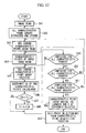
- Fig. 12 is a flow chart showing the operation of the position detection apparatus shown in Fig. 11.
- Fig. 13 is an explanatory drawing that explains the principle of position detection in the third embodiment.
- Fig. 14 is an explanatory drawing that explains the principle of position detection in the third embodiment.
- Fig. 15 is an explanatory drawing that explains the principle of position detection in the third embodiment.
- Fig. 1 is a block diagram showing the constitution of the present embodiment.
- the position detection apparatus shown in Fig. 1 is explained in the form of that equipped on an autonomous travel robot that moves indoors.
- reference symbol 1 represents two cameras that capture an object present in the field of view in the direction of movement during movement by the robot. These cameras are installed at a prescribed interval, and their mutual fields of view are aligned.
- Reference symbol 2 represents a distance image storage unit that respectively stores individual frames of images obtained by cameras 1, and is composed of two frames of image memory.
- Reference symbol 3 represents a distance image formation unit that forms distance images from two frames of images stored in image storage unit 2.
- Reference symbol 4 represents a distance image storage unit that stores the distance images formed in distance image formation unit 3.
- Reference symbol 5 represents a characteristic point extraction unit that extracts characteristic points from images stored in image storage unit 2 or distance image storage unit 4.
- Reference symbol 6 represents a position detection unit that detects self-position based on the results of characteristic point extraction in characteristic point extraction unit 5.
- Reference symbol 7 represents a movement control unit that controls the movement of the robot by referring to the results of position detection by position detection unit 6.
- distance image data is the set of three-dimensional coordinate values of a measurement point on the surface of an object in the field of view of cameras 1.
- Fig. 2 is a flow chart showing the operation by which characteristic points are tracked continuously from brightness images stored in image storage unit 2 and distance images stored in distance image storage unit 4 by characteristic point extraction unit 5 and position detection unit 6 to detect self-position based on that position data.
- Each of the processing shown in the flow chart of Fig. 2 is executed repeatedly each time an image is captured by cameras 1.
- the two cameras 1 operate as stereo cameras, and brightness images are captured with each camera which are then respectively stored in image storage unit 2.
- distance image formation unit 3 forms a distance image by determining the corresponding points of the pixels of each image from the two brightness images acquired with two cameras 1, which is then stored in distance image storage unit 4.
- distance images are generated using so-called sub-pixels by interpolating between pixels in order to obtain more precise distance images with fewer pixels.
- the brightness and distance images of each pixel are expressed with 256 gradations.
- the pixels of distance images represent the distance to the surface of an object in the field of view of a sensor in 256 gradations.
- XYZ coordinates can be specified from a camera position to a single point on the surface of an object present in three-dimensional space according to the position of the pixels in a distance image.
- accuracy can be improved by using laser radar, milliwave radar or ultrasonic waves in place of the cameras.
- output values from the distance sensor may also be used directly without representing distance data in 256 gradations.
- Cameras 1 and distance image formation unit 3 execute this operation repeatedly.
- characteristic point extraction unit 5 reads images stored in image storage unit 2 (Step S1).
- characteristic point extraction unit 5 extracts characteristic points from the brightness images that have been read, and stores these characteristic points in characteristic point extraction unit 5 (Step S2).
- the characteristic points mentioned here refer to points equivalent to an unchanging characteristic amount used in image processing that characterize forms appearing in an image. Extraction of these characteristic points is performed by, for example, performing edge detection processing on brightness images and selecting those points that compose the detected edge.
- characteristic point extraction unit 5 may read distance images stored in distance image storage unit 4, and then extract characteristic points from these distance images. Characteristic points are created using two consecutively incorporated brightness images. Here, their respective times are designated as "t" and "(t+1)".
- characteristic point extraction brightness images obtained from either left or right camera 1 are used, and two types of characteristic points are stored consisting of a set of characteristic points extracted from the input image of time (t+1), and a set of characteristic points extracted from the image of time t immediately prior to the input image. Coordinate values on the image are stored for these characteristic points.
- position detection unit 6 reads a single input image characteristic point stored in characteristic point extraction unit 5 in order to determine the corresponding point of these characteristic points of two different times (Step S3). Subsequently, position detection unit 6 reads one image point of the previous image stored in characteristic point extraction unit 5 (Step S4).
- previous time t refers to the time at which Steps S1 through S17 presently being explained were performed previously, and the corresponding point between two different times t and (t+1) is obtained by Steps S1 through S17 being performed two times or more. Accordingly, when Steps S1 through S17 are performed for the first time, the process is extraordinarily executed through Step S3 and then returns to Step S1.
- position detection unit 6 calculates the certainty CA of two characteristic points and performs pattern matching with the characteristic point stored at time t (Step S5).
- m pixels x n pixels (provided m and n are natural numbers of 2 or more) around a characteristic point are selected for an input image from which a characteristic point has been extracted.
- m pixel x n pixels (provided m and n are natural numbers of 2 or more) around a characteristic point of the previous image are selected.
- the selected magnitude (m x n) of the pixels surrounding the two characteristic points may be determined arbitrarily, the number of selected pixels of the two characteristic points must be the same.
- position detection unit 6 compares certainty CA and threshold TC (Step S6).
- displacement vector da is calculated from the coordinate value as the amount of characteristic point movement over a continuous period of time, and that vector da is then stored in position detection unit 6 (Step S7).
- the process proceeds to Step S8.
- position detection unit 6 evaluates whether or not processing has been performed for all characteristic points of the previous image (Step S8). If all of the characteristic points have not been processed, the process returns to Step S4 and processing is repeated. On the other hand, if processing has been completed for all characteristic points of the previous image, position detection unit 6 evaluates whether or not processing has been performed for all characteristic points of the input image (Step S9). If all of the characteristic points have not been processed, the operation returns to Step S3 and processing is repeated. On the other hand, if processing has been completed for all characteristic points of the input image, the process proceeds to Step S10.
- results may be determined by calculating only the vicinities of the characteristic points to be determined in coordination with the required amount of movement in order to reduce the calculation processing load.
- position detection unit 6 reads the stored displacement vectors da and calculates the mean displacement vector Td (Step S10).
- position detection unit 6 reads out the stored displacement vectors da one at a time (Step S11).
- Position detection unit 6 then calculates
- position detection unit 6 judges the characteristic point used when calculating the relevant displacement vector da to be a stationary object (Step S13). On the other hand, in the case the above calculated difference is greater than threshold value A, position detection unit 6 judges the characteristic point used when calculating the relevant displacement vector da to be a moving object (Step S14). This processing is performed for all calculated displacement vectors da (Step S15) and as a result, a judgment is made as to whether a characteristic point is a stationary object or moving object for each characteristic point.
- position detection unit 6 extracts those characteristic points judged to be stationary objects for which certainty CA is the superordinate (Step S16).
- certainty CA being superordinate refers to certainty CA being superordinate the smaller the value of CA.
- Those characteristic points extracted by this extraction processing are characteristic points of a previous image (time t) that form a pair with characteristic points of the input image (time t+1), and these characteristic points serve as the reference characteristic points for calculation of self-position.
- position detection unit 6 determines characteristic point distance from the correlating points between each of the extracted reference characteristic points and the distance image stored in distance image storage unit 4, and calculates the amount the robot moved from time at which the previous image was acquired to the time at which the current image (input image) was acquired based on the amount of movement of that characteristic point and the relative position of the robot (Step S17).
- the program returns again to Step S1 and repeats the same processing on a characteristic point for which a correlation was previously obtained that has been stored in memory.
- the coordinate system here is a coordinate system defined when the robot is in the initial state, and the forward direction of the robot is designated as the X axis, while the direction that intersects this X axis is designated as the Y axis.
- a and b respectively represent arbitrary characteristic points such as columns located in a building that are extracted by the above processing.
- Data obtained by acquiring images by the robot consists of the relative position of characteristic point a (x a ,y a ) and the relative position of characteristic point b (x b ,y b ) shown in Fig. 4.
- the symbol ⁇ here represents the angle of rotation of the robot about the Z axis, and is positive during counter-clockwise rotation.
- Robot angle of rotation ⁇ and robot position (x t ,y t ) can thus be determined according to the above.
- a and b were hypothesized to be known in the above explanation, since an unknown object is treated here, the absolute positions of a and b cannot be determined.
- the positions of a and b are determined based on the position of the robot at time t, and the displacement of robot position (amount of movement of the robot) is determined based on displacement da of the relative positions of a and b obtained at time t+1.
- robot position at time t+1 can then be determined.
- robot position can be easily determined based on the relative positions of a and b in the case a and b are known.
- the calculated position is notified to movement control unit 7 after which robot movement is controlled by movement control unit 7 based on this position.
- movement control unit 7 may be made to output position detection instructions to characteristic point extraction unit 5 so that characteristic point extraction unit 5 begins the processing shown in Fig. 2 upon receiving those position detection instructions.
- the displacement of the position of the stationary object can be determined over time, and the amount of self-movement can be determined each time from the amount of this displacement, thereby enabling self-position to be detected accurately.
- tracking may be performed by determining the history of movement of a characteristic point from two or more images and extracting stationary objects.
- robot position (x t+1 ,y t+1 ) can be determined by determining the target position from the target relative position and robot position (x t ,y t ) at time t based on the amount of displacement of the position of that target at time t+1.
- the position at time t+k can be similarly detected based on the amount of displacement of (x t+k ,y t+k ) during time k.
- distance image formation unit 3 shown in Fig. 1 may be replaced with radar and so forth using ultrasonic waves or electromagnetic waves. At this time, the measuring field of view of the radar is set to be the same as that of cameras 1 shown in Fig. 1. In addition, in the case of obtaining distance images using radar and so forth, only a single camera 1 should be provided for obtaining brightness images.
- characteristic points may move outside the frame as the moving body approaches a characteristic point, thereby preventing detection of position. Consequently, characteristic points for which the amount of movement is calculated are successively switched by performing the processing shown in Fig. 2 on all of a plurality of characteristic points. In this case, however, since the error in measured distance increases as the characteristic point moves away from the moving body s compared with the case of approaching the moving body, if the amount of movement is made to be calculated by preferentially selecting the characteristic point within the frame that is at the shortest distance from the moving body, deterioration of movement accuracy can be prevented.
- tracking may also be performed such that the position of an object that has temporarily left the frame is stored in memory and then recognized as the same object when it again returns to inside the frame.
- FIG. 5 is a block diagram showing the constitution of another embodiment of the present invention.
- the block diagram shown in Fig. 5 is different from the block diagram shown in Fig. 1 with respect to newly providing object data storage unit 8.
- This object data storage unit 8 stores sets of characteristic points of a plurality of known stationary objects in the form of a characteristic amount, and a map of objects corresponding to the absolute positions of those stationary objects, and is referred to by characteristic point extraction unit 5 and position detection unit 6.
- Known stationary objects referred to here include such stationary objects as columns, plants, lockers and other articles of furniture in a room.
- the moving object can be controlled both efficiently and accurately.
- characteristic point extraction unit 5 reads an image stored in image storage unit 2 (Step S21). Characteristic point extraction unit 5 then extracts characteristic points from the read brightness image and stores these characteristic points in characteristic point extraction unit 5 (Step S22).
- the characteristic points referred to here are equivalent to an unchanging characteristic amount that is used in image processing that characterize forms appearing in an image.
- the characteristic amount refers to a plurality of groups of characteristic points that compose the object shape. Extraction of these characteristic points is performed by, for example, performing edge detection processing on an image and selecting a plurality of characteristic points that compose the detected edge.
- characteristic point extraction unit 5 may read distance images stored in distance image storage unit 4, and then extract characteristic points from these distance images. Characteristic points are stored in the form of sets of characteristic points extracted from an image at time t (previous image), and these characteristic points are stored using their coordinate values on the image.
- characteristic point extraction unit 5 reads those characteristic points stored inside one at a time and compares them with the plurality of object data characteristic point groups (characteristic amount) stored in object data storage unit 8 by pattern matching (Step S23).
- This comparison processing is performed by processing similar to the processing of the previously described embodiment (processing shown in Fig. 2).
- the object data referred to here indicates data comprised of the absolute coordinates of a position at which characteristic points and a stationary object are present after extracting the characteristic points of the stationary object from an image obtained in advance.
- a simple template matching method may be used for the pattern matching device used.
- characteristic point extraction unit 5 makes a judgment as to whether or not object data that coincides with or has a high degree of certainty, namely has a high correlation, with the characteristic point obtained in Step S22 was present in object data storage unit 8, or in other words, whether or not a known object was present (Step S24).
- position detection unit 6 determines absolute self-position from this known stationary object and relative self-position (Step S25). This absolute position is calculated from the absolute coordinates of the known object and the relationship between a known object obtained from a distance image stored in distance image storage unit 4 and relative self-position.
- characteristic point extraction unit 5 makes a judgment as to whether the characteristic point extracted in Step S22 is a moving object or a stationary object (Step S26).
- the respective absolute positions are determined from the relative positional relationship with self-position based on self-position data determined immediately before (Step S27).
- This judgment processing is performed according to the processing of Steps S4 through S13 and S14 shown in Fig. 2. A judgment is then made as to whether the stationary object obtained as a result of this judgment processing could also have been tracked in the previous processing (time t) (Step S28).
- This judgment is made by comparing the amount of consistency between the characteristic amount previously stored in object data storage unit 8 and the current characteristic amount by pattern matching.
- accuracy can be improved by comparing the absolute position of the characteristic amount previously stored in object data storage unit 8 in Step S30 with the position determined Step S27, and adding a judgment that tracking could have been performed in the case they are in close proximity.
- position detection unit 6 determines absolute self-position from the relative positions of the stationary object and self-position (Step S29).
- characteristic point extraction unit 5 determines the absolute position of the new characteristic point based on the characteristic point of a new stationary object and the absolute self-position at time t previously determined in Step S25 or Step S29, and then stores that absolute position in object data storage unit 8 (Step S30). Calculation of the amount of movement is performed according to the processing of Steps S3 through S17 shown in Fig. 2.
- Step S28 judgment of whether or not the positions are in close proximity is made by stipulating a distance threshold value and judging whether or not the previous position and current position are within this distance.
- statistical processing may also be performed. This may be performed by assuming that a certain characteristic amount could have been tracked for a continuous amount of time, calculating each of the variance values for the variance in relative position (x,y) with respect to self-position obtained from distance images for a position on an image of that characteristic amount, and judging those within the range of variance to be identical objects and those outside the range of variance to be different objects at the time the variance values converge.
- predefined variance values set in advance may be used, or predefined values may be used that have been set and stored for each object in object data storage unit 8.
- a function may be used such that variance values are changed at the square of the distance.
- reference symbol AR indicates the action area
- origin G is determined in advance within this action area AR.
- Reference symbol R indicates a robot
- reference symbol K4 a known stationary object
- reference symbol U5 an unknown object. The angle of rotation ⁇ of robot R is ignored in Fig. 7 to simplify the explanation.
- Step S28 the judgment of Step S28 is made for all characteristic amounts, and in Step S29, self-position is determined from the relative positions with all characteristic amounts, after which self-absolute position is determined from the average value.
- movement control unit 7 is able to accurately control movement.
- Step S23 an explanation is provided of the operation using a specific example with reference to Fig. 9.
- the explanation here deals with the example of a robot moving from point A to point B and further moving to point C.
- objects K1, K2 and K3, for which the absolute coordinates are known are recognized to be present at point A.
- Position detection unit 6 determines absolute self-position from the coordinate values of the absolute positions of objects K1 and K2 since the distance of object K3 among objects K1, K2 and K3 is the greatest (Step S25). At this time, position detection unit 6 determines the coordinate values of unknown objects U1 and U2 by calculation, and stores those values in internal memory (Step S30).
- the robot then moves while determining self-position based on the positions of unknown objects U1 and U2 for which the relative positions have become known (Step S29), and in the case of reaching a position at which unknown objects U1 and U2 cannot be captured by the cameras, moves to point B while determining self-position based on known object K3 (Step S25) and finally determines the absolute position of point B.
- position data and object data relating to unknown objects U1 and U2 are updated.
- the robot changes direction and heads in the direction of point C.
- unknown objects U3 and U4 are captured by cameras 1.
- self-position is determined by determining the amount of movement based on unknown objects U3 and U4, and adding the determined amount of movement to the relative coordinate values of point B (Step S29).
- a known object is captured during the course of moving to point C, absolute self-position is determined based on that known object, and the error in relative position determined according to the amount of movement is reset.
- robot position may be calculated using a Kalman filter based on extracted reference characteristic points. By using this Kalman filter, robot position can be calculated while taking into consideration variations in distance data and so forth.
- Equation (1) an explanation is provided of the processing for calculating robot position in the case of using a Kalman filter.
- the Kalman filter used here is an extended Kalman filter, and the its status equation is shown in Equation (1).
- x t and y t are the x and y values on the x and y axes
- ⁇ t is the angle of rotation about the z axis
- T t is the distance when moving from time step t to time step (t+1).
- Equation (1) the second term from the right is the amount of change in distance control at time t from movement control unit 7, while the third term represents the system noise associated with robot control at time t.
- the coordinate system used here is the same as that of Fig. 5, while the meanings of each of the parameters that express the status of robot position are shown in Fig. 10.
- Equation (2) is the observation equation of characteristic point a
- Equation (3) is the observation equation of characteristic point b.
- E 1 ( a x - x t ) cos (- ⁇ t ) - ( a y - y t ) sin (- ⁇ t )
- E 2 ( a x - x t ) sin (- ⁇ t ) + ( a y - y t ) cos (- ⁇ t )
- E 3 ( b x - x t ) cos (- ⁇ t ) - ( b y - y t ) sin (- ⁇ t )
- E 4 ( b x -x t ) sin (- ⁇ t ) + ( b y -y t ) cos (- ⁇ t )
- the second term on the right side in Equations (2) and (3) represents noise.
- Equations (1) through (3) are used in the processing of Steps S25 and S29 shown in Fig. 2.
- robot angle of rotation ⁇ t+1 and robot position (x t+1 ,y t+1 ) can be determined.
- robot position can be detected more accurately since both system noise and measurement noise are taken into consideration as compared with calculating geometrically as described above.
- the covariance of observed values relative to characteristic points that converges within the Kalman filter can be used as the variance values of those characteristic points.
- self-position may also be determined to include height by expanding to the direction of height (z direction).
- Fig. 11 is a block diagram indicating the constitution of a position detection apparatus in a third embodiment.
- reference symbol 1 indicates a camera
- reference symbol 5 indicates a characteristic point extraction unit.
- Reference symbol 8 indicates an object data storage unit.
- Reference symbol 9 indicates a correlation processing unit that determines the correlation between two characteristic points.
- Reference symbol 10 indicates a self-position determination unit that determines self-position based on the processing results of correlation processing unit 9.
- image storage unit 2 which stores obtained images, and movement control unit 7 are omitted.
- related constituents are deleted.
- Fig. 13 depicts a scene in the forward direction F ⁇ of the robot at position M being captured with the camera followed by selection of characteristic point groups from the resulting image.
- characteristic point groups W are correlated with position M and stored in object data storage unit 8. Since the characteristic point groups here do not allow identification of their respective relative positions due to occlusion and so forth, stored positions are correlated for all characteristic points.
- Fig. 14 indicates the example of there being 9 positions at which characteristic point groups are stored in memory (Ml through M9), these positions being preset at positions over which the robot is likely to pass. If characteristic point groups extracted from image captured with a camera facing in the direction of forward direction F ⁇ of the robot from each preset position M1 through M9 are designated as W1 through W9, each position (referred to as a characteristic point acquisition position) M1 through M9 and characteristic point groups W1 through W9 are correlated into respective pairs which are then stored in advance in object data storage unit 8.
- the correlation between the characteristic point groups extracted from the image captured with the camera facing in the direction of forward direction F ⁇ and pre-stored characteristic point groups W1 through W9 is determined, and characteristic point group Wn (where n is any of 1 through 9) having the highest correlation is judged to be the position over which the robot is passing, and the characteristic point acquisition position Mn (where n is any of 1 through 9) that forms a pair with this characteristic point group Wn becomes the self-position.
- position M4 at which this characteristic point group W4 was acquired is determined to be the self-position.
- characteristic point extraction unit 5 reads an image captured with camera 1 (Step S41). Characteristic point extraction unit 5 then extracts all characteristic point groups from the read image and stores them in internal memory (Step S42). On the other hand, correlation processing unit 9 reads one characteristic point group stored in object data storage unit 8 (Step S43). Continuing, correlation processing unit 9 reads one characteristic point of the input image (image captured with camera 1) from characteristic point extraction unit 5 (Step S44). Moreover, correlation processing unit 9 selects one characteristic point from the characteristic point group read in Step S43 (Step S45).
- correlation processing unit 9 calculates the certainty CA between the characteristic point read in Step S44 and the characteristic point selected in Step S45 (Step S46), and compares this with a predetermined threshold value Tc (Step S47). As a result, the program proceeds to Step S49 unless CA > Tc. On the other hand, if CA > Tc, the sum S of CA determined for each processing loop is determined (Step S48). Since the sum S of CA is determined for each characteristic point group, however, sum S of certainty CA is obtained for the number of characteristic point groups only. Correlation processing unit 9 then repeats the processing of Steps S45 through S48 for all characteristic points that compose the characteristic point group read in Step S43 (Step S49).
- correlation processing unit 9 repeats the processing of Steps S44 through S48 for all characteristic points that compose the characteristic point groups stored in Step S42 (Step S50), and then repeats the processing of Steps S43 through S48 for all the characteristic point groups stored in Step S42 (Step S51).
- the processing of Steps S42 through S48 consists of determining the certainty for all of the characteristic points that compose the characteristic point groups extracted from the input image as well as all of the characteristic points stored in object data storage unit 8. Furthermore, in the processing of Steps S44 through S50, the processing load can be reduced by determine certainty after selecting those characteristic points in close proximity to the image pixels.
- self-position determination unit 10 selects the characteristic point group for which the sum S of certainty CA determined in Step 48 is large (Step S52). Self-position is then determined by reading the characteristic point acquisition position that forms a pair with the selected characteristic point group from object data storage unit 8 (Step S53) followed by output of that position as self-position data.
- two left and right cameras that compose a stereo camera of the robot may be used to compare a pre-stored characteristic point group W for each camera and arithmetically determine correlation.
- self-position can be determined according to the difference in the magnitudes of the degree of correlation of the camera images relative to the same characteristic point group W.
- the direction of offset to the left and right of position M can be detected from the difference in correlation values detected with each camera relative to position M corresponding to characteristic point group W. Consequently, since the number in the left and right directions of position M at which the characteristic point group is obtained can be reduced, the bother associated with capturing an image in advance can be reduced considerably.
- they should be used by selecting cameras arranged in the left and right directions.
- Figs. 13 and 14 were explained assuming a single direction for the direction of image capturing at each position M1 through M9, if images in a plurality of directions are captured at each position, characteristic point groups are extracted for all resulting images, and those characteristic point groups are stored in object data storage unit 8, self-position can be detected by the same processing even if the forward direction of the robot differs at each position.
- the robot may also be made to extract characteristic point groups from enlarged or reduced images by using a zoom function of the camera equipped on the robot itself. If this is done, it becomes easier to obtain a correlation in a case such as when the robot is positioned between positions M2 and M5 shown in Fig. 14.
- the robot may also be made to extract characteristic point groups from images obtained in a state in which a head unit equipped with a camera swings horizontally and vertically. When this is done, it becomes easy to obtain a correlation between characteristic points even in cases in which the robot is acting in a direction different from the forward direction when it acquired a stored characteristic point group.
- position detection processing previously described in the three embodiments may be suitably combined corresponding to the environment in which the robot moves, and self-position may be detected by selecting the necessary processing.
- a program for realizing the processing shown in Figs. 2, 6 and 12 may be recorded on a recording medium that can be read by a computer, the program recorded on the recording medium may be loaded into a computer system, and that program may then be run to perform position detection processing.
- the "computer system” referred to here includes an OS, peripherals and other hardware.
- the "computer system” also includes a web site providing environment (or display environment).
- a "recording medium that can be read by a computer” refers to a flexible disc, magneto-optical disc, ROM, CD-ROM or other portable media as well as a storage device such as a hard disk built into the computer system.
- the "recording medium that can be read by a computer” also includes that which retains a program for a fixed amount of time in the manner of non-volatile memory (RAM) inside a computer system comprised of a server and clients in the case the program is transmitted via the Internet or other network or via a telephone line or other communication line.
- RAM non-volatile memory
- the above program may be transferred to another computer system via a transfer medium or by a transfer wave within a transfer medium from a computer system that contains the program in a storage device and so forth.
- the "transfer medium” that transfers the program refers to a medium having a function for transferring information in the manner of the Internet or other network or a telephone line or other communication line.
- the above program may also be that for realizing a portion of the functions described above.
- it may also be that which realizes the above functions by combining with a program already stored in a computer system in the form of a so-called differential file (differential program).
- the present invention offers the advantage of being able to accurately detect self-position.
- extraction of the stationary object can be performed independently, the constitution can be simplified since it is not necessary to provide a map and so forth in which the positions of stationary objects have been defined in advance.
- the present invention is particularly suited to a humanoid robot that moves by the use of legs.
- the present invention offers the advantage of being able to detect self-position more accurately.
- the present invention offers the advantage of being able to detect self-position more accurately.
- the present invention offers the advantage of enabling updating of map data and object data to be performed automatically.
- the object of the present invention is to provide a position detection apparatus that is able to easily detect self-position during autonomous movement by a humanoid robot that moves by the use of legs or automobile.
- the present invention discloses a position detection apparatus that detects the position of a moving object, said position detection apparatus being provided with a brightness image acquisition device that acquires a brightness image of the forward field of view of the moving object, a distance image acquisition device having the same field of view as the brightness image acquisition device that acquires a distance image simultaneous to acquisition of a brightness image by the brightness image acquisition device, a characteristic point extraction device that extracts respective characteristic points from the brightness images of at least two consecutive frames, and a reference characteristic point selection device that calculates the amount of displacement of a position between two frames of a characteristic point extracted by the characteristic point extraction device based on a distance image, and selects a reference characteristic point for calculating self-position according to said amount of displacement.
Landscapes
- Physics & Mathematics (AREA)
- Electromagnetism (AREA)
- Engineering & Computer Science (AREA)
- General Physics & Mathematics (AREA)
- Radar, Positioning & Navigation (AREA)
- Remote Sensing (AREA)
- Image Analysis (AREA)
- Manipulator (AREA)
- Image Processing (AREA)
- Length Measuring Devices By Optical Means (AREA)
- Control Of Position, Course, Altitude, Or Attitude Of Moving Bodies (AREA)
Applications Claiming Priority (4)
| Application Number | Priority Date | Filing Date | Title |
|---|---|---|---|
| JP2000157299 | 2000-05-26 | ||
| JP2000157299 | 2000-05-26 | ||
| JP2001124943A JP4672175B2 (ja) | 2000-05-26 | 2001-04-23 | 位置検出装置、位置検出方法、及び位置検出プログラム |
| JP2001124943 | 2001-04-23 |
Publications (3)
| Publication Number | Publication Date |
|---|---|
| EP1158309A2 true EP1158309A2 (de) | 2001-11-28 |
| EP1158309A3 EP1158309A3 (de) | 2005-02-09 |
| EP1158309B1 EP1158309B1 (de) | 2013-08-21 |
Family
ID=26592745
Family Applications (1)
| Application Number | Title | Priority Date | Filing Date |
|---|---|---|---|
| EP01112618.2A Expired - Lifetime EP1158309B1 (de) | 2000-05-26 | 2001-05-23 | Verfahren und Vorrichtung zur Positionserfassung |
Country Status (3)
| Country | Link |
|---|---|
| US (1) | US7239339B2 (de) |
| EP (1) | EP1158309B1 (de) |
| JP (1) | JP4672175B2 (de) |
Cited By (9)
| Publication number | Priority date | Publication date | Assignee | Title |
|---|---|---|---|---|
| EP1519340A1 (de) * | 2003-09-23 | 2005-03-30 | Electronics and Telecommunications Research Institute | Einrichtungssystem und Verfahren für RFID-Bake |
| EP1610090A2 (de) * | 2004-06-23 | 2005-12-28 | Kabushiki Kaisha Topcon | Verfahren zum Verknüpfen von Stereobildern und System zum Bereitstellen von dreidimensionalen Daten |
| EP1777498A1 (de) * | 2005-10-19 | 2007-04-25 | Aisin Aw Co., Ltd. | Verfahren zur Bestimmung der Fahrzeugbewegungsdistanz, Vorrichtung zur Bestimmung der Fahrzeugbewegungsdistanz, Verfahren zur Bestimmung der aktuellen Fahrzeugposition und Vorrichtung zur Bestimmung der aktuellen Fahrzeugposition |
| EP1574821A3 (de) * | 2004-03-08 | 2009-11-04 | Kabushiki Kaisha Topcon | Vermessungsverfahren und Vermessungsinstrument |
| US8630755B2 (en) | 2010-09-28 | 2014-01-14 | Kabushiki Kaisha Topcon | Automatic taking-off and landing system |
| US8666571B2 (en) | 2011-01-04 | 2014-03-04 | Kabushiki Kaisha Topcon | Flight control system for flying object |
| US9020666B2 (en) | 2011-04-28 | 2015-04-28 | Kabushiki Kaisha Topcon | Taking-off and landing target instrument and automatic taking-off and landing system |
| US9544575B2 (en) | 2011-09-28 | 2017-01-10 | Kabushiki Kaisha Topcon | Image acquiring device and image acquiring system |
| CN109358315A (zh) * | 2018-10-12 | 2019-02-19 | 华中科技大学 | 一种辅助目标间接定位方法及系统 |
Families Citing this family (84)
| Publication number | Priority date | Publication date | Assignee | Title |
|---|---|---|---|---|
| JP3656910B2 (ja) * | 2002-07-22 | 2005-06-08 | 住友電気工業株式会社 | スクライブ溝の加工方法及びスクライブ装置 |
| JP2004061446A (ja) * | 2002-07-31 | 2004-02-26 | Fujitsu Ten Ltd | パターンマッチング処理方法及び画像処理装置 |
| EP1413974A1 (de) * | 2002-10-24 | 2004-04-28 | Hewlett-Packard Company | Hybride Messtechniken zur Positionsbestimmung |
| JP4171282B2 (ja) * | 2002-10-25 | 2008-10-22 | 富士重工業株式会社 | 地形認識装置および地形認識方法 |
| EP1517115B1 (de) * | 2003-09-19 | 2016-05-11 | Omron Corporation | Mehrfachsensorsystem |
| US9052717B1 (en) | 2004-02-11 | 2015-06-09 | Enovation Controls, Llc | Watercraft speed control device |
| US20080243321A1 (en) | 2005-02-11 | 2008-10-02 | Econtrols, Inc. | Event sensor |
| JP3879740B2 (ja) * | 2004-02-13 | 2007-02-14 | 日産自動車株式会社 | 道路領域検出装置 |
| KR100763234B1 (ko) * | 2004-06-11 | 2007-10-04 | 삼성전자주식회사 | 주행 상태를 감지하는 시스템 및 방법 |
| JP4216772B2 (ja) * | 2004-06-17 | 2009-01-28 | 株式会社東芝 | 自己位置同定装置および自己位置同定方法 |
| EP1759334A2 (de) * | 2004-06-22 | 2007-03-07 | Sarnoff Corporation | Verfahren und vorrichtung für visuelle odometrie |
| US20090196491A1 (en) * | 2004-08-30 | 2009-08-06 | Maxwell Leslie Stainlay | Method for automated 3d imaging |
| US8000837B2 (en) | 2004-10-05 | 2011-08-16 | J&L Group International, Llc | Programmable load forming system, components thereof, and methods of use |
| KR100569472B1 (ko) * | 2004-10-05 | 2006-04-07 | 현대자동차주식회사 | 엔진의 연료 분무 선단 속도 계측 시스템 및 방법 |
| US9207675B1 (en) * | 2005-02-11 | 2015-12-08 | Enovation Controls, Llc | Event sensor |
| KR100638220B1 (ko) * | 2005-04-23 | 2006-10-27 | 엘지전자 주식회사 | 주행로봇의 위치감지장치 및 그를 구비한 로봇청소기 |
| US8306662B2 (en) | 2005-04-23 | 2012-11-06 | Lg Electronics Inc. | Position detection device for mobile robot and robot cleaner including the same |
| DE102005035746B4 (de) * | 2005-07-29 | 2010-02-18 | Siemens Ag | Verfahren zur Bestimmung einer Relativposition einer mobilen Einheit durch Vergleich von Scans einer Umgebung und mobile Einheit |
| JP2007094743A (ja) * | 2005-09-28 | 2007-04-12 | Zmp:Kk | 自律移動型ロボットとそのシステム |
| CN100419605C (zh) * | 2005-11-09 | 2008-09-17 | 沈阳新松机器人自动化股份有限公司 | 一种现场总线位置控制装置 |
| JP5112666B2 (ja) * | 2006-09-11 | 2013-01-09 | 株式会社日立製作所 | 移動装置 |
| CN101200065B (zh) * | 2006-12-13 | 2010-10-06 | 沈阳新松机器人自动化股份有限公司 | 现场总线位置控制装置 |
| KR100912874B1 (ko) | 2007-06-28 | 2009-08-19 | 삼성전자주식회사 | 이동 로봇의 리로케이션 방법 및 장치 |
| KR100884904B1 (ko) * | 2007-09-12 | 2009-02-19 | 아주대학교산학협력단 | 평행 투영 모델을 이용한 자기위치 인식 방법 |
| US8264537B2 (en) * | 2007-09-28 | 2012-09-11 | The Mainz Group Llc | Photogrammetric networks for positional accuracy |
| JP2009115621A (ja) * | 2007-11-06 | 2009-05-28 | Toshiba Corp | 移動体画像追尾装置 |
| JP4337929B2 (ja) * | 2007-12-25 | 2009-09-30 | トヨタ自動車株式会社 | 移動状態推定装置 |
| JP5349804B2 (ja) * | 2008-01-10 | 2013-11-20 | 株式会社日立産機システム | 移動ロボットシステム及びその制御方法 |
| DE102008024308B4 (de) * | 2008-05-20 | 2010-12-09 | Eads Deutschland Gmbh | Verfahren zur Detektion nichtkooperativen Luftverkehrs an Bord eines Luftfahrzeugs |
| DE102008039606A1 (de) * | 2008-08-25 | 2010-03-04 | GM Global Technology Operations, Inc., Detroit | Kraftfahrzeug mit einem Abstandssensor und einem Bilderfassungssystem |
| JP5409189B2 (ja) * | 2008-08-29 | 2014-02-05 | キヤノン株式会社 | 撮像装置及びその制御方法 |
| KR101022785B1 (ko) * | 2008-09-17 | 2011-03-17 | 포항공과대학교 산학협력단 | 신경망과 진화연산을 이용한 로봇의 환경 지도 작성 방법 |
| KR101038702B1 (ko) | 2008-10-24 | 2011-06-03 | 전자부품연구원 | 로봇의 위치 검출방법 |
| JP4816748B2 (ja) | 2009-03-06 | 2011-11-16 | ソニー株式会社 | ナビゲーション装置及びナビゲーション方法 |
| JP5278878B2 (ja) * | 2009-03-23 | 2013-09-04 | 国立大学法人 宮崎大学 | 管内面形状測定装置 |
| JP4810582B2 (ja) * | 2009-03-26 | 2011-11-09 | 株式会社東芝 | 移動体画像追尾装置および方法 |
| JPWO2011145239A1 (ja) | 2010-05-19 | 2013-07-22 | 国立大学法人東京工業大学 | 位置推定装置、位置推定方法及びプログラム |
| WO2011163454A1 (en) | 2010-06-25 | 2011-12-29 | Trimble Navigation Ltd. | Method and apparatus for image-based positioning |
| US8963954B2 (en) * | 2010-06-30 | 2015-02-24 | Nokia Corporation | Methods, apparatuses and computer program products for providing a constant level of information in augmented reality |
| JP2012034196A (ja) * | 2010-07-30 | 2012-02-16 | Olympus Corp | 撮像端末、データ処理端末、撮像方法、及びデータ処理方法 |
| US9232128B2 (en) | 2011-03-28 | 2016-01-05 | Nec Corporation | Image capture position and image capture direction estimation device, image capture device, image capture position and image capture direction estimation method and program |
| JP5947016B2 (ja) * | 2011-10-26 | 2016-07-06 | 株式会社ディスコ | キーパターン決定方法 |
| WO2013076829A1 (ja) | 2011-11-22 | 2013-05-30 | 株式会社日立製作所 | 自律移動システム |
| JP5780142B2 (ja) * | 2011-12-07 | 2015-09-16 | 富士通株式会社 | 画像処理装置、画像処理方法 |
| US20140039675A1 (en) * | 2012-08-03 | 2014-02-06 | Nimer Mohammed Ead | Instructional humanoid robot apparatus and a method thereof |
| JP6015250B2 (ja) * | 2012-08-31 | 2016-10-26 | 富士通株式会社 | 画像処理装置、画像処理方法及び画像処理プログラム |
| US9036865B2 (en) * | 2012-09-12 | 2015-05-19 | International Business Machines Corporation | Location determination for an object using visual data |
| JP6265499B2 (ja) * | 2012-11-06 | 2018-01-24 | Soinnホールディングス合同会社 | 特徴量抽出装置及び場所推定装置 |
| US9560246B2 (en) * | 2012-12-14 | 2017-01-31 | The Trustees Of Columbia University In The City Of New York | Displacement monitoring system having vibration cancellation capabilities |
| US9142063B2 (en) * | 2013-02-15 | 2015-09-22 | Caterpillar Inc. | Positioning system utilizing enhanced perception-based localization |
| JP6094279B2 (ja) * | 2013-03-14 | 2017-03-15 | 株式会社国際電気通信基礎技術研究所 | 追跡装置、追跡プログラムおよび追跡方法 |
| US9081382B2 (en) | 2013-03-15 | 2015-07-14 | Fresenius Medical Care Holdings, Inc. | Autonomous vehicle comprising extracorporeal blood treatment machine |
| JP6129981B2 (ja) * | 2013-10-01 | 2017-05-17 | 株式会社日立製作所 | 移動体位置推定装置および移動体位置推定方法 |
| TWI534453B (zh) * | 2014-02-18 | 2016-05-21 | 原相科技股份有限公司 | 相對位置定位系統與追蹤系統 |
| JP6380523B2 (ja) * | 2014-02-26 | 2018-08-29 | 株式会社ソシオネクスト | 画像認識システムおよび半導体集積回路 |
| US10310054B2 (en) * | 2014-03-21 | 2019-06-04 | The Boeing Company | Relative object localization process for local positioning system |
| GB201409625D0 (en) * | 2014-05-30 | 2014-07-16 | Isis Innovation | Vehicle localisation |
| FR3022036B1 (fr) * | 2014-06-05 | 2016-07-15 | Aldebaran Robotics | Dispositif de detection a plans croises d'un obstacle et procede de detection mettant en oeuvre un tel dispositif |
| DE102014212781A1 (de) | 2014-07-02 | 2016-01-07 | Continental Automotive Gmbh | Verfahren zum Ermitteln und Bereitstellen einer Landmarke zur Positionsbestimmung für ein Fahrzeug |
| JP6369898B2 (ja) * | 2014-08-07 | 2018-08-08 | 日産自動車株式会社 | 自己位置算出装置及び自己位置算出方法 |
| JP6369897B2 (ja) * | 2014-08-07 | 2018-08-08 | 日産自動車株式会社 | 自己位置算出装置及び自己位置算出方法 |
| US10339389B2 (en) * | 2014-09-03 | 2019-07-02 | Sharp Laboratories Of America, Inc. | Methods and systems for vision-based motion estimation |
| JP6352133B2 (ja) * | 2014-09-26 | 2018-07-04 | 株式会社Screenホールディングス | 位置検出装置、基板処理装置、位置検出方法および基板処理方法 |
| WO2016206108A1 (en) | 2015-06-26 | 2016-12-29 | SZ DJI Technology Co., Ltd. | System and method for measuring a displacement of a mobile platform |
| US9738399B2 (en) * | 2015-07-29 | 2017-08-22 | Hon Hai Precision Industry Co., Ltd. | Unmanned aerial vehicle control method and unmanned aerial vehicle using same |
| JP6556015B2 (ja) | 2015-10-09 | 2019-08-07 | ソニー株式会社 | 情報処理装置、位置および/または姿勢の推定方法、およびコンピュータプログラム |
| MX2018006642A (es) * | 2015-12-14 | 2018-08-01 | Panasonic Ip Corp America | Metodo de codificacion de datos tridimencionales, metodos de decodificacion de datos tridimensionales, dispositivo de codificacion de datos tridimensionales y dispositivo de decodificacion de datos tridimensionales. |
| JP6864433B2 (ja) * | 2016-01-29 | 2021-04-28 | 東芝ライフスタイル株式会社 | 電気掃除機 |
| JP6626410B2 (ja) | 2016-06-03 | 2019-12-25 | 株式会社Soken | 自車位置特定装置、自車位置特定方法 |
| JP2018051728A (ja) * | 2016-09-30 | 2018-04-05 | ファナック株式会社 | 対象物の三次元位置を検出する検出方法および検出装置 |
| JP6803745B2 (ja) * | 2016-12-28 | 2020-12-23 | 日立Geニュークリア・エナジー株式会社 | 検査装置 |
| WO2019021412A1 (ja) * | 2017-07-27 | 2019-01-31 | 日本電気株式会社 | 位置推定装置、位置推定方法及びプログラム記録媒体 |
| US10440280B2 (en) * | 2017-09-21 | 2019-10-08 | Advanced Semiconductor Engineering, Inc. | Optical system and method for operating the same |
| WO2019131198A1 (ja) | 2017-12-28 | 2019-07-04 | ソニー株式会社 | 制御装置、および制御方法、プログラム、並びに移動体 |
| CN108900805B (zh) * | 2018-07-11 | 2021-01-12 | 长沙理工大学 | 一种基于计算机网络的艺术设计用品移动实时监控系统 |
| KR102356469B1 (ko) * | 2018-10-17 | 2022-01-28 | 현대모비스 주식회사 | 차량의 후진 주행 지원 장치 및 방법 |
| KR102593422B1 (ko) * | 2018-10-17 | 2023-10-26 | 현대모비스 주식회사 | 차량의 후진 주행 지원 장치 및 그 제어방법 |
| US11616914B2 (en) * | 2018-12-28 | 2023-03-28 | Intel Corporation | Tracking objects using sensor rotation |
| US11347226B2 (en) * | 2019-04-25 | 2022-05-31 | Lg Electronics Inc. | Method of redefining position of robot using artificial intelligence and robot of implementing thereof |
| DE112019007064B4 (de) * | 2019-04-25 | 2024-05-08 | Mitsubishi Electric Corporation | Bewegungsbetrag-schätzeinrichtung, bewegungsbetrag-schätzverfahren und bewegungsbetrag-schätzprogramm |
| JP7180739B2 (ja) * | 2019-06-19 | 2022-11-30 | 株式会社リコー | 情報処理装置、情報処理システム、情報処理方法及び情報処理プログラム |
| CN110653837B (zh) * | 2019-10-31 | 2021-08-13 | 灵动科技(北京)有限公司 | 自主移动装置及仓储物流系统 |
| KR102252888B1 (ko) * | 2020-01-03 | 2021-05-17 | 포테닛 주식회사 | 공간 내에서 이송로봇의 위치 검출장치 및 방법 |
| CN112025697B (zh) * | 2020-07-10 | 2022-06-17 | 浙江工业大学 | 一种全向移动机器人的积分模型预测控制方法 |
Family Cites Families (18)
| Publication number | Priority date | Publication date | Assignee | Title |
|---|---|---|---|---|
| GB2116000B (en) * | 1982-03-02 | 1985-05-01 | Elliott Bros | Guidance system |
| JPH0820253B2 (ja) * | 1986-11-27 | 1996-03-04 | 神鋼電機株式会社 | 移動ロボツトにおける位置検出方法 |
| US5051906A (en) * | 1989-06-07 | 1991-09-24 | Transitions Research Corporation | Mobile robot navigation employing retroreflective ceiling features |
| US5819016A (en) * | 1993-10-05 | 1998-10-06 | Kabushiki Kaisha Toshiba | Apparatus for modeling three dimensional information |
| JP2501010B2 (ja) * | 1993-10-25 | 1996-05-29 | インターナショナル・ビジネス・マシーンズ・コーポレイション | 移動ロボットの誘導装置 |
| JP3555159B2 (ja) * | 1994-03-02 | 2004-08-18 | 日本電気株式会社 | 3次元形状復元方法および装置 |
| JPH0843055A (ja) * | 1994-07-29 | 1996-02-16 | Canon Inc | 3次元物体形状認識方法及び装置 |
| US5777690A (en) * | 1995-01-20 | 1998-07-07 | Kabushiki Kaisha Toshiba | Device and method for detection of moving obstacles |
| JPH0933247A (ja) * | 1995-07-19 | 1997-02-07 | Mitsubishi Electric Corp | 画像物体検出装置 |
| JPH0953939A (ja) * | 1995-08-18 | 1997-02-25 | Fujitsu Ltd | 自走車の自己位置測定装置および自己位置測定方法 |
| JPH10222665A (ja) * | 1997-01-31 | 1998-08-21 | Fujitsu Ten Ltd | 画像認識装置 |
| NO312862B1 (no) * | 1997-07-15 | 2002-07-08 | Forsvarets Forsknings | Fremgangsmåte for å bestemme en geografisk posisjon av en mobilenhet i et radiosystem |
| SE511504C2 (sv) * | 1997-10-17 | 1999-10-11 | Apogeum Ab | Sätt och anordning för associering av anonyma reflektorer till detekterade vinkellägen |
| JP4005679B2 (ja) * | 1997-11-19 | 2007-11-07 | 富士重工業株式会社 | 自律走行車の周囲環境認識装置 |
| JP3850541B2 (ja) * | 1998-02-18 | 2006-11-29 | 富士重工業株式会社 | 高度計測装置 |
| AUPP299498A0 (en) * | 1998-04-15 | 1998-05-07 | Commonwealth Scientific And Industrial Research Organisation | Method of tracking and sensing position of objects |
| JP3596314B2 (ja) * | 1998-11-02 | 2004-12-02 | 日産自動車株式会社 | 物体端の位置計測装置および移動体の通行判断装置 |
| US6678394B1 (en) * | 1999-11-30 | 2004-01-13 | Cognex Technology And Investment Corporation | Obstacle detection system |
-
2001
- 2001-04-23 JP JP2001124943A patent/JP4672175B2/ja not_active Expired - Fee Related
- 2001-05-23 EP EP01112618.2A patent/EP1158309B1/de not_active Expired - Lifetime
- 2001-05-26 US US09/866,151 patent/US7239339B2/en not_active Expired - Lifetime
Non-Patent Citations (1)
| Title |
|---|
| None |
Cited By (14)
| Publication number | Priority date | Publication date | Assignee | Title |
|---|---|---|---|---|
| CN100462680C (zh) * | 2003-09-23 | 2009-02-18 | 韩国电子通信研究院 | 使用交通工具的射频识别标记装配系统及其方法 |
| EP1519340A1 (de) * | 2003-09-23 | 2005-03-30 | Electronics and Telecommunications Research Institute | Einrichtungssystem und Verfahren für RFID-Bake |
| US7764809B2 (en) | 2004-03-08 | 2010-07-27 | Kabushiki Kaisha Topcon | Surveying method and surveying instrument |
| EP1574821A3 (de) * | 2004-03-08 | 2009-11-04 | Kabushiki Kaisha Topcon | Vermessungsverfahren und Vermessungsinstrument |
| EP1610090A3 (de) * | 2004-06-23 | 2009-12-30 | Kabushiki Kaisha Topcon | Verfahren zum Verknüpfen von Stereobildern und System zum Bereitstellen von dreidimensionalen Daten |
| EP1610090A2 (de) * | 2004-06-23 | 2005-12-28 | Kabushiki Kaisha Topcon | Verfahren zum Verknüpfen von Stereobildern und System zum Bereitstellen von dreidimensionalen Daten |
| US7804996B2 (en) | 2004-06-23 | 2010-09-28 | Kabushiki Kaisha Topcon | Method for associating stereo image and three-dimensional data preparation system |
| EP1777498A1 (de) * | 2005-10-19 | 2007-04-25 | Aisin Aw Co., Ltd. | Verfahren zur Bestimmung der Fahrzeugbewegungsdistanz, Vorrichtung zur Bestimmung der Fahrzeugbewegungsdistanz, Verfahren zur Bestimmung der aktuellen Fahrzeugposition und Vorrichtung zur Bestimmung der aktuellen Fahrzeugposition |
| US8630755B2 (en) | 2010-09-28 | 2014-01-14 | Kabushiki Kaisha Topcon | Automatic taking-off and landing system |
| US8666571B2 (en) | 2011-01-04 | 2014-03-04 | Kabushiki Kaisha Topcon | Flight control system for flying object |
| US9020666B2 (en) | 2011-04-28 | 2015-04-28 | Kabushiki Kaisha Topcon | Taking-off and landing target instrument and automatic taking-off and landing system |
| US9544575B2 (en) | 2011-09-28 | 2017-01-10 | Kabushiki Kaisha Topcon | Image acquiring device and image acquiring system |
| US10602129B2 (en) | 2011-09-28 | 2020-03-24 | Kabushiki Kaisha Topcon | Image acquiring device and image acquiring system |
| CN109358315A (zh) * | 2018-10-12 | 2019-02-19 | 华中科技大学 | 一种辅助目标间接定位方法及系统 |
Also Published As
| Publication number | Publication date |
|---|---|
| JP4672175B2 (ja) | 2011-04-20 |
| US20010055063A1 (en) | 2001-12-27 |
| EP1158309A3 (de) | 2005-02-09 |
| US7239339B2 (en) | 2007-07-03 |
| EP1158309B1 (de) | 2013-08-21 |
| JP2002048513A (ja) | 2002-02-15 |
Similar Documents
| Publication | Publication Date | Title |
|---|---|---|
| EP1158309A2 (de) | Verfahren und Vorrichtung zur Positionserfassung | |
| JP5148669B2 (ja) | 位置検出装置、位置検出方法、及び位置検出プログラム | |
| US8401783B2 (en) | Method of building map of mobile platform in dynamic environment | |
| EP2460629B1 (de) | Steuerverfahren zur lokalisierung und navigation eines mobilen roboters und mobiler roboter damit | |
| Wolf et al. | Robust vision-based localization by combining an image-retrieval system with Monte Carlo localization | |
| US7333631B2 (en) | Landmark, apparatus, and method for effectively determining position of autonomous vehicles | |
| Jang et al. | Color landmark based self-localization for indoor mobile robots | |
| US8024072B2 (en) | Method for self-localization of robot based on object recognition and environment information around recognized object | |
| US6025790A (en) | Position recognizing system of autonomous running vehicle | |
| Gonzalez et al. | Combined visual odometry and visual compass for off-road mobile robots localization | |
| Nair et al. | Moving obstacle detection from a navigating robot | |
| Ferreira et al. | Real-time optical SLAM-based mosaicking for unmanned underwater vehicles | |
| Andreasson et al. | Mini-SLAM: Minimalistic visual SLAM in large-scale environments based on a new interpretation of image similarity | |
| Iocchi et al. | Self-localization in the RoboCup environment | |
| Wolf et al. | Using an image retrieval system for vision-based mobile robot localization | |
| Ayala et al. | Visual localization of a mobile robot in indoor environments using planar landmarks | |
| Di Marco et al. | Set membership localization and mapping for autonomous navigation | |
| Xian et al. | Fusing stereo camera and low-cost inertial measurement unit for autonomous navigation in a tightly-coupled approach | |
| Alves et al. | Cost-effective indoor localization for autonomous robots using kinect and wifi sensors | |
| Kang et al. | Development of a peripheral-central vision system for small UAS tracking | |
| Schleicher et al. | Real-Time wide-angle stereo visual SLAM on large environments using SIFT features correction | |
| Fitzgibbons et al. | Application of vision in simultaneous localization and mapping | |
| Ferreira et al. | A comparison between different feature-based methods for ROV vision-based speed estimation | |
| Zeng et al. | An introduction for the indoor localization systems and the position estimation algorithms | |
| CN114326695B (zh) | 自走车跟随系统及自走车跟随方法 |
Legal Events
| Date | Code | Title | Description |
|---|---|---|---|
| PUAI | Public reference made under article 153(3) epc to a published international application that has entered the european phase |
Free format text: ORIGINAL CODE: 0009012 |
|
| AK | Designated contracting states |
Kind code of ref document: A2 Designated state(s): AT BE CH CY DE DK ES FI FR GB GR IE IT LI LU MC NL PT SE TR |
|
| AX | Request for extension of the european patent |
Free format text: AL;LT;LV;MK;RO;SI |
|
| PUAL | Search report despatched |
Free format text: ORIGINAL CODE: 0009013 |
|
| AK | Designated contracting states |
Kind code of ref document: A3 Designated state(s): AT BE CH CY DE DK ES FI FR GB GR IE IT LI LU MC NL PT SE TR |
|
| AX | Request for extension of the european patent |
Extension state: AL LT LV MK RO SI |
|
| 17P | Request for examination filed |
Effective date: 20050624 |
|
| AKX | Designation fees paid |
Designated state(s): DE FR GB |
|
| REG | Reference to a national code |
Ref country code: DE Ref legal event code: R079 Ref document number: 60148257 Country of ref document: DE Free format text: PREVIOUS MAIN CLASS: G01S0011120000 Ipc: G01S0005160000 |
|
| RIC1 | Information provided on ipc code assigned before grant |
Ipc: G01S 5/16 20060101AFI20110907BHEP |
|
| GRAP | Despatch of communication of intention to grant a patent |
Free format text: ORIGINAL CODE: EPIDOSNIGR1 |
|
| GRAS | Grant fee paid |
Free format text: ORIGINAL CODE: EPIDOSNIGR3 |
|
| GRAA | (expected) grant |
Free format text: ORIGINAL CODE: 0009210 |
|
| AK | Designated contracting states |
Kind code of ref document: B1 Designated state(s): DE FR GB |
|
| REG | Reference to a national code |
Ref country code: GB Ref legal event code: FG4D |
|
| RIN1 | Information on inventor provided before grant (corrected) |
Inventor name: MATSUNAGA, SHINICHI Inventor name: SAKAGAMI, YOSHIAKI Inventor name: NAGAI, TAKAAKI |
|
| REG | Reference to a national code |
Ref country code: DE Ref legal event code: R096 Ref document number: 60148257 Country of ref document: DE Effective date: 20131017 |
|
| PLBE | No opposition filed within time limit |
Free format text: ORIGINAL CODE: 0009261 |
|
| STAA | Information on the status of an ep patent application or granted ep patent |
Free format text: STATUS: NO OPPOSITION FILED WITHIN TIME LIMIT |
|
| 26N | No opposition filed |
Effective date: 20140522 |
|
| PGFP | Annual fee paid to national office [announced via postgrant information from national office to epo] |
Ref country code: GB Payment date: 20140521 Year of fee payment: 14 |
|
| PGFP | Annual fee paid to national office [announced via postgrant information from national office to epo] |
Ref country code: FR Payment date: 20140509 Year of fee payment: 14 Ref country code: DE Payment date: 20140521 Year of fee payment: 14 |
|
| REG | Reference to a national code |
Ref country code: DE Ref legal event code: R097 Ref document number: 60148257 Country of ref document: DE Effective date: 20140522 |
|
| REG | Reference to a national code |
Ref country code: DE Ref legal event code: R119 Ref document number: 60148257 Country of ref document: DE |
|
| GBPC | Gb: european patent ceased through non-payment of renewal fee |
Effective date: 20150523 |
|
| REG | Reference to a national code |
Ref country code: FR Ref legal event code: ST Effective date: 20160129 |
|
| PG25 | Lapsed in a contracting state [announced via postgrant information from national office to epo] |
Ref country code: DE Free format text: LAPSE BECAUSE OF NON-PAYMENT OF DUE FEES Effective date: 20151201 Ref country code: GB Free format text: LAPSE BECAUSE OF NON-PAYMENT OF DUE FEES Effective date: 20150523 |
|
| PG25 | Lapsed in a contracting state [announced via postgrant information from national office to epo] |
Ref country code: FR Free format text: LAPSE BECAUSE OF NON-PAYMENT OF DUE FEES Effective date: 20150601 |