EP1157837A2 - Verfahren und Vorrichtung zur Registereinstellung an einer Mehrfarbendruckmaschine - Google Patents
Verfahren und Vorrichtung zur Registereinstellung an einer Mehrfarbendruckmaschine Download PDFInfo
- Publication number
- EP1157837A2 EP1157837A2 EP01110797A EP01110797A EP1157837A2 EP 1157837 A2 EP1157837 A2 EP 1157837A2 EP 01110797 A EP01110797 A EP 01110797A EP 01110797 A EP01110797 A EP 01110797A EP 1157837 A2 EP1157837 A2 EP 1157837A2
- Authority
- EP
- European Patent Office
- Prior art keywords
- image
- printing
- areas
- register
- designed
- Prior art date
- Legal status (The legal status is an assumption and is not a legal conclusion. Google has not performed a legal analysis and makes no representation as to the accuracy of the status listed.)
- Granted
Links
Images


Classifications
-
- H—ELECTRICITY
- H04—ELECTRIC COMMUNICATION TECHNIQUE
- H04N—PICTORIAL COMMUNICATION, e.g. TELEVISION
- H04N1/00—Scanning, transmission or reproduction of documents or the like, e.g. facsimile transmission; Details thereof
- H04N1/46—Colour picture communication systems
- H04N1/50—Picture reproducers
- H04N1/506—Reproducing the colour component signals picture-sequentially, e.g. with reproducing heads spaced apart from one another in the subscanning direction
-
- B—PERFORMING OPERATIONS; TRANSPORTING
- B41—PRINTING; LINING MACHINES; TYPEWRITERS; STAMPS
- B41F—PRINTING MACHINES OR PRESSES
- B41F13/00—Common details of rotary presses or machines
- B41F13/08—Cylinders
- B41F13/10—Forme cylinders
- B41F13/12—Registering devices
- B41F13/14—Registering devices with means for displacing the cylinders
-
- B—PERFORMING OPERATIONS; TRANSPORTING
- B41—PRINTING; LINING MACHINES; TYPEWRITERS; STAMPS
- B41F—PRINTING MACHINES OR PRESSES
- B41F33/00—Indicating, counting, warning, control or safety devices
- B41F33/0081—Devices for scanning register marks
-
- G—PHYSICS
- G03—PHOTOGRAPHY; CINEMATOGRAPHY; ANALOGOUS TECHNIQUES USING WAVES OTHER THAN OPTICAL WAVES; ELECTROGRAPHY; HOLOGRAPHY
- G03G—ELECTROGRAPHY; ELECTROPHOTOGRAPHY; MAGNETOGRAPHY
- G03G15/00—Apparatus for electrographic processes using a charge pattern
- G03G15/01—Apparatus for electrographic processes using a charge pattern for producing multicoloured copies
- G03G15/0142—Structure of complete machines
- G03G15/0178—Structure of complete machines using more than one reusable electrographic recording member, e.g. one for every monocolour image
- G03G15/0194—Structure of complete machines using more than one reusable electrographic recording member, e.g. one for every monocolour image primary transfer to the final recording medium
-
- B—PERFORMING OPERATIONS; TRANSPORTING
- B41—PRINTING; LINING MACHINES; TYPEWRITERS; STAMPS
- B41P—INDEXING SCHEME RELATING TO PRINTING, LINING MACHINES, TYPEWRITERS, AND TO STAMPS
- B41P2233/00—Arrangements for the operation of printing presses
- B41P2233/50—Marks on printed material
- B41P2233/52—Marks on printed material for registering
-
- G—PHYSICS
- G03—PHOTOGRAPHY; CINEMATOGRAPHY; ANALOGOUS TECHNIQUES USING WAVES OTHER THAN OPTICAL WAVES; ELECTROGRAPHY; HOLOGRAPHY
- G03G—ELECTROGRAPHY; ELECTROPHOTOGRAPHY; MAGNETOGRAPHY
- G03G2215/00—Apparatus for electrophotographic processes
- G03G2215/01—Apparatus for electrophotographic processes for producing multicoloured copies
- G03G2215/0103—Plural electrographic recording members
- G03G2215/0119—Linear arrangement adjacent plural transfer points
-
- G—PHYSICS
- G03—PHOTOGRAPHY; CINEMATOGRAPHY; ANALOGOUS TECHNIQUES USING WAVES OTHER THAN OPTICAL WAVES; ELECTROGRAPHY; HOLOGRAPHY
- G03G—ELECTROGRAPHY; ELECTROPHOTOGRAPHY; MAGNETOGRAPHY
- G03G2215/00—Apparatus for electrophotographic processes
- G03G2215/01—Apparatus for electrophotographic processes for producing multicoloured copies
- G03G2215/0151—Apparatus for electrophotographic processes for producing multicoloured copies characterised by the technical problem
- G03G2215/0158—Colour registration
- G03G2215/0161—Generation of registration marks
Definitions
- the invention relates to a method for register adjustment on a multi-color printing press with color printing units assigned to different printing inks, at least an image cylinder, image generation devices for generating partial color images, especially of electrostatic latent partial color images, on which at least an image cylinder, a support for printing substrates and at least one image transfer point for the transfer of the partial color images to the printing substrates, whereby an assignment of the image generation locations on the at least one image cylinder to Achievement of a register match of the part-color images made during printing is done by creating both the beginning of the image and the generation of Areas of the partial color images on the basis of the printing and the evaluation of Register marks is set.
- the invention further relates to a device according to the above-mentioned method for register setting on a multicolour printing machine with different printing colors assigned color printing units, at least one image cylinder, image generation devices for generating partial color images, especially electrostatic latent partial color images on the at least one image cylinder, one Carrier for printing substrates and at least one image transfer point for the transfer of the partial color images on printing substrates, sensors for position detection and at least one setting device for assigning the positions of the image generation points on the at least one image cylinder to achieve a register match the partial color images during printing, with at least one register sensor for Detection of register marks arranged and configured the setting device is that it causes the printing of register marks and evaluates them in such a way that on this basis they generate the beginning of the image as well as the generation of Areas of the partial color images.
- the invention further relates to a multi-color machine with a device of aforementioned type.
- the printing of colored representations takes place in that several partial color images are printed on top of each other. These are usually the colors Yellow, magenta and cyan as well as black. Special colors are also available if required added. By printing these colors on top of each other you can create all color compositions achieve. The quality of the prints depends largely on the register Print the partial color images on top of each other. In conventional printing processes the printing forms by means of test printing and register marks printed with them corrected until an exact overprint, that is, a register accuracy of pressure.
- the image cylinders are each made by means of an image generation device described with pixels, for example by electrostatic Charges generated and these are provided with adhering color pigments.
- the color pigments are then transferred to a printing substrate.
- the printing process can maintain register accuracy by using the image forming devices be controlled accordingly. Since the illustration for every print new, does not have to be a one-time setting as with conventional printing processes be made, but it can be a default and a scheme be provided which makes corrections for each individual print. Of course this applies not only to the application of electrostatic latent images but also all other printing processes in which pixels are used by means of a digital control be applied.
- the invention is therefore based on the object, method and device of the introduction mentioned type in such a way that the register setting with reasonable Computational effort and high accuracy can be realized and in particular the data reasonable computing effort can be obtained and processed.
- the object is achieved with respect to the method in that at least one image page is printed with register marks that have a different length than the prints, whose register should be set, and that to determine the correction values Data of the register marks of the at least one image page are recorded, for positions of image and related substrate-bearing elements and the imaging devices are controlled according to the correction values.
- the object is achieved with respect to the device in that it has at least one Has adjustment device which is designed such that it the pressure of causes at least one image page with register marks that have a different length has than the prints whose registers are to be set and that the at least one setting device is designed such that it for determination the correction values the data of the registered register marks for positions of image and Relates substrate-bearing elements and the imaging devices controls according to these correction values .
- the object is achieved with respect to the multicolor printing machine in that it is equipped with a device of the aforementioned type,
- the invention has the advantage that it provides a method and an apparatus be through which with reasonable computing effort within a short time Correction values are determined from the actual and target values and the corrections are carried out can be.
- the basic idea of the invention consists in the separability of the actual values the beginning of the image from the actual values of the areas of the partial color images by the proposed design of register marks. This separation can be an intermediate step, For example, to calculate the correction values for the Images are generated or separate correction values can be determined and be taken into account.
- At least one test print is carried out in which an image page with register marks is printed, the longer is than the prints whose registers are to be set or if several image pages created that these are shorter than the prints whose registers are set should be.
- Such length deviations make it possible to correct the errors of the Image starts, which are due to an assignment error of the image generation to one another are conditioned to separate from the errors of the image areas which of Transmission errors of the generated partial color images from the image generation to their Transfer to a print substrate.
- These different causes of Errors enable them to be separated because they differ from the prints to be created different lengths of image pages with register marks linking the errors of the Eliminates the beginning of the image with the errors in the areas of the partial color images.
- This Separation is required at least within the calculation of correction values a register setting with reasonable computing effort and high accuracy realize.
- the difficulty of this detection is that the mean value of the Curve in reality has no straight course.
- the captured Curve can be a superposition of two curves, which is used to record the errors of the beginning of the image and the error of the areas of the partial color images are separated from each other have to. This can be done, for example, by a computer that has the characteristics recognizes based on an algorithm. This separation is possible due to the different Length of the image page or image pages to the prints to be created because the Calculation is therefore possible with fewer unknowns and is easier to undertake.
- the assignment of the data of the register marks can Positions of the image- and substrate-bearing elements as an immediate position assignment or as an indirect position assignment over recorded times.
- a further development of the method provides that the data of the register marks Positions of the image cylinders and the carrier are related and the image forming devices controlled on the image cylinders to achieve the target values on the carrier become.
- the at least one Setting device is designed such that it registers the data Positions of the image cylinder and the carrier in relation and thus the image generation devices on the image cylinders to achieve the target values on the carrier controls. This configuration is especially for multi-color printing presses where the Partial color images are transferred directly from the image cylinders to printing substrates, which are on a carrier.
- the at least one setting device be designed such that it also stores the data of the register marks on positions of the image transfer cylinders relates and includes in the control of the imaging devices. This Measure is particularly important because for the necessary contact from Image cylinder and image transfer cylinder at least one of the surfaces one can have certain elasticity. As a rule, it is provided that the Image transfer cylinders are equipped with an elastic jacket.
- the method is expediently designed such that separate correction values are determined for the generation of the beginning of the image and the areas of the partial color images, the generation of the areas is based on the beginning of the image.
- the at least one setting device is corresponding to the device Trained way. Is an image start exactly with a corresponding control positioned, so the areas of the partial color images can follow, where each individual area according to the correction values for the areas of Partial color images can be positioned.
- the at least one image page with register marks can have an excess length, under certain circumstances then a single image page for the determination of the correction values is sufficient.
- Another possibility is that several compared to the Print, whose register should be set, create shorter image pages. in the In the former case, it is expedient if the length of an image side is chosen in this way becomes that several periods of errors of areas of the partial color images are detected become. In the second case it is useful if the shorter sides of the picture are like this are positioned so that there are several periods of errors in picture beginnings are included.
- the register marks are designed in such a way that that the actual positions of the beginning of the image can be determined from them and that the correction values can be determined from a comparison of the actual with the target positions.
- the register marks are designed such that the Have the actual positions of the areas recorded and that the correction values from a comparison the actual with the target positions can be determined.
- the device it is proposed that that it is designed such that it from the data of the detected Register marks determined the correction values in the aforementioned manner.
- the areas of the partial color images can be pixel rows or groups to deal with pixel lines.
- the device is then corresponding to the calculation formed by areas, the pixel rows or groups of pixel rows could be.
- the position assignment can be done indirectly A time assignment can be made, or it can be used directly as a position assignment be made. In the latter case, it is a particularly useful embodiment suggested that the location of the areas defined angular positions of the image cylinder be assigned.
- the device it is proposed that it with equipped at least one sensor for at least one position detection and such is designed so that they define the position of the areas angular positions of the image cylinders assigns. It is particularly expedient to use angular sequences of the image cylinders to define the size of the areas and these defined angular sequences assign. The device is also designed for a corresponding assignment.
- This assignment to defined angular sequences of the image cylinders is a simple one Method to make different transfers of areas in different Positions of the elements transmitting them in the generation of the partial color images in this way to eliminate that afterwards the register accuracy on the printing substrate is guaranteed.
- a simple correction of the size of the areas can be done by a The distance between the pixel lines can be changed.
- the method is preferably designed such that from the data of the register marks the separate recording of the actual values of the image beginnings and the actual values of the areas of the partial color images takes place in that the by registering the registration marks data obtained using appropriate algorithms due to their different Characteristics are separated.
- the Device contains a computer that is loaded with algorithms through which it passes the registration of the register marks obtained data due to the different Characteristics of the actual values of the image beginnings and the actual values of the areas separate.
- the measure according to the invention also offers the Printing different lengths of the image pages has the advantage that the calculation with reasonable effort and can be done quickly enough. Situations in which such a separation is not possible are due to the inventive Measures excluded.
- test print of the at least one image side Presetting of a register before printing on a printing substrate takes place and the calculation is used so that the first printed substrate is fully in register.
- the calculation according to the invention provides the correction values the great advantage that machines can be designed such that also different individual pages can be printed with full register. It is advisable if the test print is printed on the substrate for printing substrates and after the Evaluation is removed again.
- the device with a Device for removing sample prints of image pages from the carrier.
- test print for register control can also be made during the printing of the printing substrates take place, the test prints for example areas of the substrate for printing substrates not covered by printing substrates are applied and can be removed after the evaluation.
- This measure has for example the advantage that a drift correction is detected during printing and Countermeasures are immediately carried out using appropriate correction values can be.
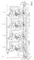
- Such a multi-color printing machine 1 generally consists of four and more color printing units 6, 6 ', 6 ", 6"'. For simplification, only two color printing units 6 and 6 'have been shown. These color printing units 6, 6 'have image cylinders 2, 2', ... and image generating devices 3, 3 ', ... for generating partial color images 7, 7', ..., for example electrostatic latent images. These partial color images 7, 7 ', ... are transferred from the image cylinders 2, 2', ... to image transfer cylinders 13, 13 ', ..., and then from these image transfer cylinders 13, 13', ... to printing substrates 15 to be applied. Each color printing unit 6, 6 ', ... applies a partial color image 7, 7', ... which together produce the color printing.
- the prints 14, the registers of which are to be set, have image starts 10 and are divided into areas 10 ', 10 ", ..., 10 n , this division being made for each partial color image 7, 7' in order to create the areas 10 , 10 ', 10 ", ..., 10 n in such a way that register-accurate overprinting of both the image beginnings 10 and the areas 10', 10", ..., 10 n can be achieved.
- the devices 3, 3 ', ... are controlled in such a way that the image formation sites 11, 11', ... the image beginnings 10 and the areas 10 ', 10 ", ..., 10 n in position the image cylinders 2, 2 ', ... in such a way that the partial color images 7, 7', ... are printed on each other with respect to all defined areas 10, 10 ', 10 ", ..., 10 n .
- sensors 20 are provided for the position detection of all image and substrate-carrying elements 2, 2 ', ..., 4, 13, 13', ...
- a sensor 21 is provided for the detection of printing substrates 15, which issues a corresponding message to the setting devices 22, 22 ', 22 ", 22"".
- the printing substrates 15 are in the direction of arrow 26 from a carrier 4 for Printing substrates 15 transported and at each color printing unit 6, 6 'at an image transfer point 5 'with a partial color image 7, 7', ...
- the illustrated embodiment of the invention proposes to assign the defined areas 10, 10 ', 10 ", ..., 10 n of the partial color images 7, 7', ... to defined angular positions 18 of the image cylinders 2, 2 ', ... in this way that each area 10, 10 ', 10 ", ..., 10 n is assigned to a defined angular sequence 19 of the respective image cylinder 2, 2', ...
- the defined angle sequences 19 and the defined areas 10, 10 ', 10 ", ..., 10 n are drawn much larger than they are actually realized. The latter would be so small that they cannot be represented in this way in the drawing A subdivision of the greatest delicacy is necessary to achieve quality prints.
- Fig. 2 shows an embodiment of a multi-color printing press 1 with the implementation of a register setting according to the invention.
- the structure and mode of operation correspond to that described above.
- each color printing unit 6, 6 ', 6 ", 6"' is assigned a setting device 22, 22 ', 22 ", 22"' which the devices 3, 3 ', ... for generating the partial color images 7, 7 ', ... controls such that the image formation points 11, 11', ... are placed on the image cylinders 2, 2 ', ... in such a way that the partial color images 7, 7', ... upon transmission a printing substrate 15 are printed one above the other in register.
- the invention provides that before the creation of a print 14, the Register is set, i.e. before a printing substrate 15 runs through the machine, image pages 8, 8 'are printed as a test print on the carrier 4 for printing substrates 15, contain the register marks 9, 9 ', 9 ", 9"'.
- a register mark 9 is created by the device 3 for generating the Partial color image 7 is generated on the image cylinder 2 and then by means of Image transfer cylinder 13 transferred to the carrier 4.
- register marks 9 ', 9 ", 9”' are created by the color printing units 6 ', 6 ", 6"'.
- These register marks 9, 9 ', 9 ", 9”' are detected by means of a register sensor 23, and the data 16 of the register marks 9, 9 ', 9 ", 9”' to the setting devices 22, 22 ', 22 ", 22”' given.
- sensors 20 are provided for the position detections. Conveniently These are angular position transmitters that support all image and substrate carriers Elements 2, 2 ', ..., 4, 13, 13' are assigned.
- a problem with the detection of the data 16 of the register marks 9, 9 ', 9 ", 9”"by the register sensor 23 is that two different ones are present in the measured data 16 of the register marks 9, 9', 9", 9 "' Incorrect errors, namely the errors with regard to the image beginnings 10 and the errors with regard to the defined areas 10 ', 10 ", ..., 10 n of the partial color images 7, 7', ....
- errors with regard to the beginning of the image 10 are allocation errors of the image generation points 11, 11 ', ... of the individual color printing units 6, 6', 6 ", 6"'and the errors of the areas 10', 10 ", ..., 10 n of the partial color images 7, 7 ', ... transmission errors with regard to the transfer of the partial color images 7, 7', ... from the image cylinders 2, 2 ', ... to the image transfer points 5, 5', 5 ", 5"' on the printing substrates 15, both errors require different corrections.
- the setting devices 22, 22 ', 22 ", 22"' on the basis of the data 16 from the register marks 9, 9 ', 9 ", 9”' each apply the corresponding correction values 17 for the image generation points 11, 11 ', which may be summarized as setting commands.
- these correction values 17 are also made up of correction values 17 'for the image beginnings 10 and correction values 17 "for the areas 10', 10", ..., 10 n of the partial color images 7, 7 ', .. . together.
- the beginning of the image 10 is first corrected for each partial color image 7, 7 ', ... and then the corrections for the regions 10', 10 ", ..., 10 n are carried out .
- the data must be evaluated before the correction values 17 are determined 16 of the register marks 9, 9 ', 9 ", 9"' take place such that at least arithmetically there are correction values 17 'for the image beginnings 10 and correction values 17 "for the areas 10', 10", ..., 10 n Thereafter, the correction values 17 'and 17 "are combined again to corresponding control signals for the image generating devices 3, 3', ....
- FIG. 3 serves to explain the problem to be solved here, which represents an example of curves 32, 32 ′ resulting from measurements of the register sensor 23 of deviations of measuring points 33 from the target position 34.
- the deviations 28 from the target position 34 against the time 29 or preferably the positions 29 of the carrier 4 are recorded.
- the positions 29 can be detected by means of an angular position transmitter 20, which is assigned to a roller 25, preferably the drive roller of the carrier 4.
- the curves 32, 32 'resulting from many measuring points 33 usually have an offset 31, 31' at their beginning, that is to say an axis section other than zero. These are the errors for the image beginnings 10 of partial color images 7, 7 ', ....
- the curves 32, 32 'then periodically describe the deviations of the areas 10', 10 ", ..., 10 n of one of the partial color images 7, 7 ', ....
- the average value 30, 30' of a curve 32, 32 ' can run as shown, but a drift is also possible, which is noticeable by an increase or decrease in the average value 30, 30.
- the offset 31, 31' with respect to a plurality of image starts 10 generally also results in a similar periodic extending curve, which is then detected in order to correct the beginning of the image 10 as well.
- the illustrated embodiment is of course only exemplary, on this It is also possible to control printing machines in which the partial color images 7, 7 ', ... transferred directly from the image cylinders 2, 2', ... to the printing substrates 15 become.
- the control can also be configured somewhat differently, for example instead of the setting devices 22, 22 ', 22 ", 22"', each of which has a printing unit 6, 6 ', 6 ", 6"' are assigned, a common control is provided for all printing units his.
- Other different configurations of the method and the mechanical Construction conceivable.
Landscapes
- Engineering & Computer Science (AREA)
- Multimedia (AREA)
- Signal Processing (AREA)
- Physics & Mathematics (AREA)
- General Physics & Mathematics (AREA)
- Mechanical Engineering (AREA)
- Inking, Control Or Cleaning Of Printing Machines (AREA)
- Color Electrophotography (AREA)
- Color, Gradation (AREA)
- Color Image Communication Systems (AREA)
- Electronic Switches (AREA)
- Manufacture Or Reproduction Of Printing Formes (AREA)
- Control Or Security For Electrophotography (AREA)
Abstract
Description
- Fig. 1
- das Prinzip einer Mehrfarbendruckmaschine, deren Register erfindungsgemäß eingestellt werden kann,
- Fig. 2
- ein Ausführungsbeispiel einer erfindungsgemäßen Registereinstellung und
- Fig. 3
- ein Beispiel einer sich aus Messungen des Registersensors ergebenden Kurve von Abweichungen.
- 1
- Mehrfarbendruckmaschine
- 2, 2', ...
- Bildzylinder
- 3, 3 , ...
- Bilderzeugungseinrichtungen zur Erzeugung von Teilfarbenbildern, beispielsweise von elektrostatischen latenten Bildern
- 4
- Träger für Drucksubstrate
- 5 5', 5", 5'''
- Bildübertragungsstellen
- 6,6',6",6"'
- Farbdruckwerke
- 7, 7'
- Teilfarbenbilder
- 8,8'
- Bildseiten
- 8
- kurze Bildseiten
- 8'
- lange Bildseiten
- 9,9',9",9"'
- Registermarken (verschiedener Farbdruckwerke)
- 10, 10', 10", ..., 10n
- definierte Bereiche der Teilfarbenbilder
- 10
- Bildanfänge / Beginn der Bebilderung
- 10', 10", ..., 10n
- Bereiche der Teilfarbenbilder, in welche die Bildfläche unterteilt ist
- 11, 11', ...
- Bilderzeugungsstellen
- 12, 12'
- Länge einer Bildseite
- 12
- kürzere Länge
- 12'
- Überlänge
- 13, 13'
- Bildübertragungszylinder
- 14
- Drucke, deren Register eingestellt werden soll
- 15
- Drucksubstrate
- 16
- Daten der Registermarken
- 17, 17', 17"
- Korrekturwert
- 17'
- Korrekturwerte für die Bildanfänge
- 17"
- Korrekturwerte für die Bereiche der Teilfarbenbilder
- 18
- definierte Winkelstellungen der Bildzylinder
- 19
- definierte Winkelsequenzen
- 20
- Sensoren für Positionserfassungen (Winkelstellungsgeber)
- 21
- Sensor für die Erfassung von Drucksubstraten
- 22, 22' 22", 22'''
- Einstellungseinrichtungen
- 23
- Registersensor
- 24
- Einrichtung zur Entfernung von Probedrucken vom Träger
- 25
- Rollen für Antrieb und Führung des Trägers
- 26
- Pfeil: Transportrichtung der Drucksubstrate
- 27
- Länge eines Drucks
- 28
- Abweichung von der Sollage
- 29
- Zeit oder Position des Trägers
- 30, 30'
- mittlerer Wert
- 31, 31'
- Offset
- 32, 32'
- Kurve, die die Abweichungen der Meßpunkte von der Sollage angibt
- 33
- Meßpunkt
- 34
- Sollage
Claims (44)
- Verfahren zur Registereinstellung an einer Mehrfarbendruckmaschine (1) mit verschiedenen Druckfarben zugeordneten Farbdruckwerken (6, 6', 6", 6"'), mindestens einem Bildzylinder (2, 2', ...), Bilderzeugungseinrichtungen (3, 3', ...) zur Erzeugung von Teilfarbenbildern (7, 7', ...), insbesondere von elektrostatischen latenten Teilfarbenbildern (7, 7', ...), auf dem mindestens einen Bildzylinder (2, 2', ...), einem Träger (4) für Drucksubstrate (15) und mindestens einer Bildübertragungsstelle (5, 5', 5", 5"') für die Übertragung der Teilfarbenbilder (7, 7', ...) auf die Drucksubstrate (15), wobei eine Zuordnung der Bilderzeugungsstellen (11, 11', ...) auf dem mindestens einen Bildzylinder (2, 2', ...) zur Erzielung einer Registerübereinstimmung der Teilfarbenbilder (7, 7', ...) beim Druck vorgenommen wird, indem sowohl die Erzeugung der Bildanfänge (10) als auch die Erzeugung von Bereichen (10', 10", ... 10n) der Teilfarbenbilder (7, 7', ...) auf der Grundlage des Drucks und der Auswertung von Registermarken (9, 9', 9", 9"') eingestellt wird,
dadurch gekennzeichnet, daß mindestens eine Bildseite (8, 8') mit Registermarken (9, 9', 9", 9"') gedruckt wird, die eine andere Länge (12, 12') aufweist als die Drucke (14), deren Register eingestellt werden soll, und daß zur Ermittlung von Korrekturwerten (17, 17', 17", 17"') die Daten (16) der Registermarken (9, 9', 9", 9"') der mindestens einen Bildseite (8, 8',...) erfaßt, zu Positionen von bild- und substrattragenden Elementen (2, 2', ..., 4, 13, 13', ...) in Bezug gesetzt und die Bilderzeugungseinrichtungen (3, 3', ...) entsprechend der Korrekturwerte (17, 17', 17") gesteuert werden. - Verfahren nach Anspruch 1,
dadurch gekennzeichnet, daß die Daten (16) der Registermarken (9, 9', 9", 9''') zu Positionen der Bildzylinder (2, 2', ...) und des Trägers (4) in Bezug gesetzt und die Bilderzeugungseinrichtungen (3, 3', ...) an den Bildzylindern (2, 2', ...) zur Erzielung der Sollwerte auf dem Träger (4) gesteuert werden. - Verfahren nach Anspruch 2,
dadurch gekennzeichnet, daß die Daten (16) der Registermarken (9, 9', 9", 9''') auch zu Positionen der Bildübertragungszylinder (13, 13', ...) in Bezug gesetzt und in die Steuerung der Bilderzeugungseinrichtungen (3, 3', ...) einbezogen werden. - Verfahren nach einem der Ansprüche 1 bis 3,
dadurch gekennzeichnet, daß getrennte Korrekturwerte (17', 17") für die Erzeugung der Bildanfänge (10) und der Bereiche (10', 10", ..., 10n) der Teilfarbenbilder (7, 7, ...) ermittelt werden, wobei sich die Erzeugung der Bereiche (10', 10", ...10n) an den Bildanfängen (10) orientiert. - Verfahren nach einem der Ansprüche 1 bis 4,
dadurch gekennzeichnet, daß die mindestens eine Bildseite (8') gegenüber den Drucken (14) eine Überlänge (12') aufweist. - Verfahren nach einem der Ansprüche 1 bis 5,
dadurch gekennzeichnet, daß mehrere gegenüber den Drucken (14) kürzere (12') Bildseiten (8) erstellt werden. - Verfahren nach Anspruch 5,
dadurch gekennzeichnet, daß die Länge (12') einer Bildseite (8') derart gewählt wird, daß mehrere Perioden von Fehlern von Bereichen (10, 10', ..., 10n) von Teilfarbenbildern (7, 7', ...) erfaßt werden können. - Verfahren nach Anspruch 6,
dadurch gekennzeichnet, daß die kürzeren (12) Bildseiten (8) derart positioniert sind, daß in ihnen mehrere Perioden von Fehlern von Bildanfängen (10) enthalten sind. - Verfahren nach einem der Ansprüche 1 bis 8,
dadurch gekennzeichnet, daß die Registermarken (9, 9', 9", 9"') derart ausgebildet sind, daß sich aus ihnen die Ist-Lagen der Bildanfänge (10) erfassen lassen und daß die Korrekturwerte (17, 17', 17") aus einem Vergleich der Ist- mit den Sollagen ermittelt werden. - Verfahren nach einem der Ansprüche 1 bis 9,
dadurch gekennzeichnet, daß die Registermarken (9, 9', 9", 9"') derart ausgebildet sind, daß sich aus ihnen die Ist-Lagen der Bereiche (10', 10'', ... 10n) erfassen lassen und daß die Korrekturwerte (17, 17', 17") aus einem Vergleich der Ist- mit den Sollagen bestimmt werden. - Verfahren nach Anspruch 10,
dadurch gekennzeichnet, daß die Bereiche (10', 10", ..., 10n) Bildpunktzeilen sind. - Verfahren nach Anspruch 10,
dadurch gekennzeichnet, daß die Bereiche (10', 10", ..., 10n) Gruppen von Bildpunktzeilen sind. - Verfahren nach einem der Ansprüche 1 bis 12,
dadurch gekennzeichnet, daß die Lage der Bereiche (10', 10", ..., 10n) definierten Winkelstellungen (18) der Bildzylinder (2, 2', ...) zugeordnet werden. - Verfahren nach Anspruch 12 oder 13,
dadurch gekennzeichnet, daß die Größe der Bereiche (10', 10", ..., 10n) definierten Winkelsequenzen (19) der Bildzylinder (2, 2', ...) zugeordnet werden. - Verfahren nach einem der Ansprüche 1 bis 14,
dadurch gekennzeichnet, daß bei einer Korrektur der Größe der Bereiche (10', 10", ..., 10n) eine Änderung des Abstands der Bildpunktzeilen vorgenommen wird. - Verfahren nach einem der Ansprüche 1 bis 15,
dadurch gekennzeichnet, daß die Korrekturwerte für die Bildanfänge (10) mittels der Istwerte für die Bereiche (10', 10", ..., 10n) bestimmt werden. - Verfahren nach Anspruch 16,
dadurch gekennzeichnet, daß die Lage der Bildanfänge (10) der Lage bestimmter, definiert beabstandeter Bereiche (z. B. 10' und 10n+1) zugeordnet werden. - Verfahren nach einem der Ansprüche 1 bis 15,
dadurch gekennzeichnet, daß die Korrekturwerte (17, 17', 17") für die Bereiche (10', 10", ..., 10n) mittels der Istwerte der Lage vieler Bildanfänge (10) bestimmt werden. - Verfahren nach einem der Ansprüche 1 bis 18,
dadurch gekennzeichnet, daß aus den Daten (16) der Registermarken (9, 9', 9", 9"') die getrennte Erfassung der Istwerte der Bildanfänge (10) und der Istwerte der Bereiche (10', 10", ..., 10n) dadurch erfolgt, daß die durch die Erfassung der Registermarken (9, 9', 9", 9''') gewonnenen Daten (16) mittels entsprechender Algorithmen aufgrund ihrer unterschiedlichen Charakteristiken getrennt werden. - Verfahren nach einem der Ansprüche 1 bis 19,
dadurch gekennzeichnet, daß der Probedruck der mindestens einen Bildseite (8, 8') zur Durchführung einer Voreinstellung des Registers vor der Bedruckung eines Drucksubstrats (15) erfolgt. - Verfahren nach Anspruch 20,
dadurch gekennzeichnet, daß der Probedruck auf den Träger (4) für Drucksubstrate (15) gedruckt und nach der Auswertung wieder entfernt wird. - Verfahren nach einem der Ansprüche 1 bis 21,
dadurch gekennzeichnet, daß Probedrucke für eine Registerregelung während der Bedruckung der Drucksubstrate (15) erfolgen. - Verfahren nach Anspruch 22,
dadurch gekennzeichnet, daß die Probedrucke auf nicht von Drucksubstraten (15) bedeckte Flächen des Trägers (4) für Drucksubstrate (15) aufgebracht und nach der Auswertung wieder entfernt werden. - Vorrichtung zur Registereinstellung nach einem Verfahren gemäß einem der Ansprüche 1 bis 23 an einer Mehrfarbendruckmaschine (1) mit verschiedenen Druckfarben zugeordneten Farbdruckwerken (6, 6', 6", 6"'), mindestens einem Bildzylinder (2, 2', ...), Bilderzeugungseinrichtungen (3, 3', ...) zur Erzeugung von Teilfarbenbildern (7, 7', ...), insbesondere von elektrostatischen latenten Teilfarbenbildern (7, 7', ...) auf dem mindestens einen Bildzylinder (2, 2', ...), einem Träger (4) für Drucksubstrate (15) und mindestens einer Bildübertragungsstelle (5, 5', 5", 5"') für die Übertragung der Teilfarbenbilder (7, 7', ...) auf Drucksubstrate (15), Sensoren (20, 21) für Positionserfassungen sowie mindestens einer Einstellungseinrichtung (22, 22', 22", 22"') zur Zuordnung der Positionen der Bilderzeugungsstellen (11, 11', ...) auf dem mindestens einen Bildzylinder (2, 2', ...) zur Erzielung einer Registerübereinstimmung der Teilfarbenbilder (7, 7', ...) beim Druck, wobei mindestens ein Registersensor (23) zur Erfassung von Registermarken (9, 9', 9", 9''') angeordnet und die mindestens eine Einstellungseinrichtung (22, 22', 22", 22''') derart ausgebildet ist, daß sie den Probedruck von Registermarken (9, 9', 9", 9''') veranlaßt und derart auswertet, daß sie auf dieser Grundlage die Erzeugung der Bildanfänge (10) als auch die Erzeugung von Bereichen (10', 10", ..., 10n) der Teilfarbenbilder (7, 7', ...) einstellt,
dadurch gekennzeichnet, daß sie mindestens eine Einstellungseinrichtung (22, 22', 22", 22''') aufweist, die derart ausgebildet ist, daß sie den Druck von mindestens einer Bildseite (8, 8') mit Registermarken (9, 9', 9", 9''') veranlaßt, die eine andere Länge (12, 12') aufweist als die Drucke (14), deren Register eingestellt werden sollen, und daß die mindestens eine Einstellungseinrichtung (22, 22', 22", 22"') derart ausgebildet ist, daß sie zur Ermittlung der Korrekturwerte (17, 17',17") die Daten (16) der erfaßten Registermarken (9, 9', 9", 9"') zu Positionen von bild- und substrattragenden Elementen (2, 2', ..., 4, 13, 13', ...) in Bezug setzt und die Bilderzeugungseinrichtungen (3, 3', ...) entsprechend dieser Korrekturwerte (17, 17', 17") steuert. - Vorrichtung nach Anspruch 24,
dadurch gekennzeichnet, daß die mindestens eine Einstellungseinrichtung (22, 22', 22", 22"') derart ausgebildet ist, daß sie die Daten (16) der Registermarken (9, 9', 9", 9"') zu Positionen der Bildzylinder (2, 2', ...) und des Trägers (4) in Bezug gesetzt und damit die Bilderzeugungseinrichtungen (3, 3', ... an den Bildzylindern (2, 2', ...) zur Erzielung der Sollwerte auf dem Träger (4) steuert. - Vorrichtung nach Anspruch 24 oder 25,
dadurch gekennzeichnet, daß die mindestens eine Einstellungseinrichtung (22, 22', 22", 22"') derart ausgebildet ist, daß sie die Daten (16) der Registermarken (9, 9', 9", 9"') auch zu Positionen der Bildübertragungszylinder (13, 13', ...) in Bezug gesetzt und in die Steuerung der Bilderzeugungseinrichtungen (3, 3', ...) einbezieht. - Vorrichtung nach einem der Ansprüche 24 bis 26,
dadurch gekennzeichnet, daß die mindestens eine Einstellungseinrichtung (22, 22', 22", 22''') getrennte Korrekturwerte (17', 17") für die Erzeugung der Bildanfänge (10) und der Berieche (10', 10", ... 10n) der Teilfarbenbilder (7, 7', ...) ermittelt und die Erzeugung der Bereiche (10', 10", ..., 10n) an den Bildanfängen (10) orientiert. - Vorrichtung nach einem der Anspräche 24 bis 27,
dadurch gekennzeichnet, daß die mindestens eine Einstellungseinrichtung (22, 22', 22", 22''') zur Auswertung von mindestens einer Bildseite (8') ausgebildet ist, die gegenüber den Drucken (14) eine Überlänge (12') aufweist. - Vorrichtung nach einem der Ansprüche 24 bis 28,
dadurch gekennzeichnet, daß die mindestens eine Einstellungseinrichtung (22, 22', 22", 22''') zur Auswertung von mehreren gegenüber den Drucken (14) kürzeren (12) Bildseiten (8) ausgebildet ist. - Vorrichtung nach Anspruch 29,
dadurch gekennzeichnet, daß sie für die Auswertung einer Bildseite (8') ausgebildet ist, die mehrere Perioden von Fehlern von Bereichen (10, 10', ..., 10n) von Teilfarbenbildern (7, 7', ...) erfaßt. - Vorrichtung nach Anspruch 30,
dadurch gekennzeichnet, daß sie für die Auswertung mehrerer kürzerer (12) Bildseiten (8) ausgebildet ist, die derart positioniert sind, daß in ihnen mehrere Perioden von Fehlern von Bildanfängen (10) enthalten sind. - Vorrichtung nach einem der Ansprüche 24 bis 31,
dadurch gekennzeichnet, daß sie derart ausgebildet ist, daß sie aus den Daten (16) der erfaßten Registermarken (9, 9', 9", 9''') die Ist-Lagen der Bildanfänge (10) und aus einem Vergleich der Ist- mit den Sollagen die Korrekturwerte (17') ermittelt. - Vorrichtung nach einem der Ansprüche 24 bis 32,
dadurch gekennzeichnet, daß sie derart ausgebildet ist, daß sie aus den Daten (16) der erfaßten Registermarken (9, 9', 9", 9"') die Ist-Lagen der Bereiche (10', 10", ..., 10n) und aus einem Vergleich der Ist- mit den Sollagen die Korrekturwerte (17") ermittelt. - Vorrichtung nach Anspruch 33,
dadurch gekennzeichnet, daß sie zur Berechnung von Bereichen (10', 10", ..., 10n), die Bildpunktzeilen sind, ausgebildet ist. - Vorrichtung nach Anspruch 34,
dadurch gekennzeichnet, daß sie zur Berechnung von Bereichen (10', 10", ..., 10n), die Gruppen von Bildpunktzeilen sind, ausgebildet ist. - Vorrichtung nach einem der Ansprüche 24 bis 35,
dadurch gekennzeichnet, daß sie mit mindestens einem Sensor (20) für mindestens eine Positionserfassung ausgestattet und derart ausgebildet ist, daß sie die Lage der Bereiche (10', 10", ..., 10n) definierten Winkelstellungen (18) der Bildzylinder (2, 2', ...) zuordnet. - Vorrichtung nach Anspruch 24 bis 36,
dadurch gekennzeichnet, daß sie derart ausgebildet ist, daß sie die Größe der Bereiche (10', 10", ..., 10n) definierten Winkelsequenzen (19) der Bildzylinder (2, 2', ...) zuordnet. - Vorrichtung nach einem der Ansprüche 35 bis 37,
dadurch gekennzeichnet, daß sie derart ausgebildet ist, daß sie eine Korrektur der Größe der Bereiche (10', 10", ..., 10n) mittels einer Änderung des Abstands der Bildpunktzeilen bewirkt. - Vorrichtung nach einem der Ansprüche 24 bis 38,
dadurch gekennzeichnet, daß sie derart ausgebildet ist, daß sie die Korrekturwerte für die Bildanfänge (10) mittels der Istwerte für die Bereiche (10', 10", ..., 10n) bestimmt. - Vorrichtung nach Anspruch 39,
dadurch gekennzeichnet, daß sie derart ausgebildet ist, daß sie die Lage der Bildanfänge (10) der Lage bestimmter, definiert beabstandeter Bereiche (z.B. 10' und 10n+1) zuordnet. - Vorrichtung nach einem der Ansprüche 24 bis 40,
dadurch gekennzeichnet, daß sie derart ausgebildet ist, daß sie die Korrekturwerte für die Bereiche (10', 10", ..., 10n) mittels Istwerte der Lage vieler Bildanfänge (10) bestimmt. - Vorrichtung nach einem der Ansprüche 24 bis 41,
dadurch gekennzeichnet, daß sie einen Rechner enthält, der mit Algorithmen geladen ist, durch die er die durch die Erfassung der Registermarken (9, 9', 9", 9''') gewonnenen Daten (16) aufgrund der unterschiedlichen Charakteristiken der Istwerte der Bildanfänge (10) und der Istwerte der Bereiche (10', 10", ..., 10n) trennt. - Vorrichtung nach einem der Ansprüche 24 bis 42,
dadurch gekennzeichnet, daß sie mit einer Einrichtung (24) zur Entfernung von Probedrucken von Bildseiten (8, 8') von dem Träger (4) ausgestattet ist. - Mehrfarbendruckmaschine (1) mit verschiedenen Druckfarben zugeordneten Farbdruckwerken (6, 6', 6", 6"'), mindestens einem Bildzylinder (2, 2', ...), Bilderzeugungseinrichtungen (3, 3', ...) zur Erzeugung von Teilfarbenbildern (7, 7', ...), insbesondere von elektrostatischen latenten Teilfarbenbildern (7, 7', ...) auf dem mindestens einen Bildzylinder (2, 2', ...), einem Träger (4) für Drucksubstrate (15) und mindestens einer Bildübertragungsstelle (5, 5', 5", 5"') für die Übertragung der Teilfarbenbilder (7, 7', ...) auf Drucksubstrate (15), Sensoren (20, 21) für Positionserfassungen sowie mindestens einer Einstellungseinrichtung (22, 22', 22", 22"') zur Zuordnung der Positionen der Bilderzeugungsstellen (11, 11', ...) auf dem mindestens einen Bildzylinder (2, 2', ...) zur Erzielung einer Registerübereinstimmung der Teilfarbenbilder (7, 7', ...) beim Druck, wobei mindestens ein Registersensor (23) zur Erfassung von Registermarken (9, 9', 9", 9''') angeordnet und die mindestens eine Einstellungseinrichtung (22, 22', 22", 22"') derart ausgebildet ist, daß sie den Probedruck von Registermarken (9, 9', 9", 9"') veranlaßt und derart auswertet, daß sie auf dieser Grundlage die Erzeugung der Bildanfänge (10) als auch die Erzeugung von Bereichen (10', 10", ..., 10n) der Teilfarbenbilder (7, 7', ...) einstellt,
dadurch gekennzeichnet, daß sie mindestens eine Einstellungseinrichtung (22, 22', 22", 22''') aufweist, die derart ausgebildet ist, daß sie den Druck von mindestens einer Bildseite (8, 8') mit Registermarken (9, 9', 9", 9"') veranlaßt, die eine andere Länge (12, 12') aufweist als die Drucke (14), deren Register eingestellt werden sollen, und daß die mindestens eine Einstellungseinrichtung (22, 22', 22", 22"') derart ausgebildet ist, daß sie zur Ermittlung der Korrekturwerte (17, 17',17") die Daten (16) der erfaßten Registermarken (9, 9', 9", 9"') zu Positionen von bild- und substrattragenden Elementen (2, 2', ..., 4, 13, 13', ...) in Bezug setzt und die Bilderzeugungseinrichtungen (3, 3', ...) entsprechend dieser Korrekturwerte (17, 17', 17") steuert.
Applications Claiming Priority (2)
| Application Number | Priority Date | Filing Date | Title |
|---|---|---|---|
| US20488300P | 2000-05-17 | 2000-05-17 | |
| US204883P | 2000-05-17 |
Publications (3)
| Publication Number | Publication Date |
|---|---|
| EP1157837A2 true EP1157837A2 (de) | 2001-11-28 |
| EP1157837A3 EP1157837A3 (de) | 2004-09-15 |
| EP1157837B1 EP1157837B1 (de) | 2009-06-24 |
Family
ID=22759869
Family Applications (1)
| Application Number | Title | Priority Date | Filing Date |
|---|---|---|---|
| EP01110797A Expired - Lifetime EP1157837B1 (de) | 2000-05-17 | 2001-05-04 | Verfahren zur Registereinstellung an einer Mehrfarbendruckmaschine |
Country Status (5)
| Country | Link |
|---|---|
| US (1) | US6615732B2 (de) |
| EP (1) | EP1157837B1 (de) |
| JP (1) | JP2002031931A (de) |
| AT (1) | ATE434522T1 (de) |
| DE (1) | DE50114945D1 (de) |
Cited By (10)
| Publication number | Priority date | Publication date | Assignee | Title |
|---|---|---|---|---|
| EP1285756A1 (de) * | 2001-08-22 | 2003-02-26 | NexPress Solutions LLC | Verfahren und Druckmaschine zum Ermitteln von Registerfehlern |
| EP1285758A1 (de) * | 2001-08-09 | 2003-02-26 | NexPress Solutions LLC | Verfahren und Bebilderungseinrichtung zur Registereinstellung |
| EP1341054A1 (de) * | 2002-02-27 | 2003-09-03 | NexPress Solutions LLC | Verfahren und Steuerungseinrichtung zum Vermeiden von Registerfehlern |
| WO2004048092A3 (de) * | 2002-11-22 | 2004-11-04 | Windmoeller & Hoelscher | Verfahren und vorrichtung zur regelung des registers einer druckmaschine |
| WO2007057392A1 (de) * | 2005-11-16 | 2007-05-24 | Siemens Aktiengesellschaft | Registerregelung bei einer druckmaschine |
| DE102006009773A1 (de) * | 2006-03-01 | 2007-09-06 | Eastman Kodak Co. | Verfahren zum Vermeiden eines Passerfehlers beim Drucken |
| EP2269824A1 (de) * | 2009-07-01 | 2011-01-05 | ELTROMAT GmbH | Verfahren und Vorrichtung zur Überwachung der passgerechten Bearbeitung von bahnförmigen Materialien in Anlagen |
| WO2011044987A1 (de) | 2009-10-16 | 2011-04-21 | Robert Bosch Gmbh | Verfahren zum ansteuern eines digitaldruckwerks und digitaldruckmaschine |
| EP2397925A1 (de) | 2010-06-21 | 2011-12-21 | Robert Bosch GmbH | Verfahren zum Ansteuern wenigstens einer mittels eines Gebersignals an eine Bearbeitungsmaschine angekoppelten Bearbeitungseinrichtung |
| DE102011122744A1 (de) | 2011-12-31 | 2013-07-04 | Robert Bosch Gmbh | Verfahren zum Ansteuern wenigstens einer formatfreien Bearbeitungseinrichtung einer Bearbeitungsmaschine |
Families Citing this family (11)
| Publication number | Priority date | Publication date | Assignee | Title |
|---|---|---|---|---|
| EP1157837B1 (de) * | 2000-05-17 | 2009-06-24 | Eastman Kodak Company | Verfahren zur Registereinstellung an einer Mehrfarbendruckmaschine |
| DE10204514B4 (de) * | 2002-02-05 | 2006-03-23 | Windmöller & Hölscher Kg | Vorrichtung und Verfahren zur Korrektur des Längsregisterfehlers, welcher durch die Beistellung auftritt |
| JP2004029443A (ja) * | 2002-06-26 | 2004-01-29 | Hitachi Printing Solutions Ltd | 画像形成装置 |
| DE10311285A1 (de) * | 2003-03-14 | 2004-09-30 | Koenig & Bauer Ag | Druckwerke einer Druckmaschine mit mindestens einem Fromzylinder |
| US7044058B2 (en) * | 2003-07-02 | 2006-05-16 | Goss International Americas, Inc. | Automatic motor phase presetting for a web printing press |
| US20080279587A1 (en) * | 2007-05-09 | 2008-11-13 | Soenke Dehn | Digital multi-color printing machine |
| KR100953475B1 (ko) * | 2008-02-19 | 2010-04-16 | 건국대학교 산학협력단 | 전자소자 연속공정 롤투롤 인쇄를 위한 초정밀 레지스터제어 방법 |
| WO2009143586A1 (en) * | 2008-05-29 | 2009-12-03 | Resmed Ltd | Flexible structure for mask, and method and apparatus for evaluating performance of a mask in use |
| ES2395182B1 (es) * | 2011-08-12 | 2013-11-28 | Comexi Group Industries, Sau | Método para controlar la operación de una máquina impresora y máquina impresora flexográfica para su implementación. |
| CN104442026B (zh) * | 2013-09-16 | 2016-08-24 | 北大方正集团有限公司 | 打印套齐方法及装置 |
| JPWO2017082380A1 (ja) * | 2015-11-13 | 2017-11-16 | ウシオ電機株式会社 | 脱臭方法および脱臭装置 |
Family Cites Families (19)
| Publication number | Priority date | Publication date | Assignee | Title |
|---|---|---|---|---|
| DE247147C (de) * | 1910-10-01 | |||
| US4546700A (en) * | 1981-12-30 | 1985-10-15 | Kollmorgen Technologies Corporation | Method and apparatus for sensing and maintaining color registration |
| US4719575A (en) * | 1984-09-14 | 1988-01-12 | Web Printing Control Co., Inc. | Method and apparatus for controlling web handling machinery |
| US5076163A (en) * | 1986-04-07 | 1991-12-31 | Quad/Tech, Inc. | Web registration control system |
| JPH0810369B2 (ja) * | 1987-11-30 | 1996-01-31 | キヤノン株式会社 | 画像形成装置 |
| CH679990A5 (de) * | 1989-06-08 | 1992-05-29 | Bobst Sa | |
| JP3078830B2 (ja) * | 1990-09-25 | 2000-08-21 | キヤノン株式会社 | 画像形成装置 |
| US5287162A (en) * | 1992-06-16 | 1994-02-15 | Xerox Corporation | Method and apparatus for correction of color registration errors |
| US5345870A (en) * | 1993-02-10 | 1994-09-13 | Miles Inc. | "Direct-to-press" positive lithographic printing plate and method for making same |
| EP0770480B1 (de) * | 1995-10-25 | 2001-12-19 | Heidelberger Druckmaschinen Aktiengesellschaft | Digitale Druckmaschine mit Registerregelung |
| JP3593832B2 (ja) * | 1997-01-31 | 2004-11-24 | 富士ゼロックス株式会社 | 画像形成装置 |
| JP3499715B2 (ja) * | 1997-06-05 | 2004-02-23 | 富士通株式会社 | 印刷装置 |
| JPH1138791A (ja) * | 1997-07-23 | 1999-02-12 | Fuji Xerox Co Ltd | 画像記録装置 |
| JP3428913B2 (ja) * | 1997-11-28 | 2003-07-22 | キヤノン株式会社 | 画像形成装置及び調整方法、並びに記憶媒体 |
| JP3932715B2 (ja) * | 1999-03-02 | 2007-06-20 | 松下電器産業株式会社 | カラー画像形成装置 |
| JP2001142278A (ja) * | 1999-11-11 | 2001-05-25 | Canon Inc | レジストレーション補正方法 |
| EP1156384B1 (de) * | 2000-05-17 | 2008-04-16 | Eastman Kodak Company | Verfahren und Vorrichtung zur Registereinstellung an einer Mehrfarbendruckmaschine sowie Mehrfarbendruckmaschine |
| EP1157837B1 (de) * | 2000-05-17 | 2009-06-24 | Eastman Kodak Company | Verfahren zur Registereinstellung an einer Mehrfarbendruckmaschine |
| CH694184A5 (fr) * | 2000-12-27 | 2004-08-31 | Bobst Sa | Dispositif de lecture de marques de rep'rage dans une machine d'impression polychrome. |
-
2001
- 2001-05-04 EP EP01110797A patent/EP1157837B1/de not_active Expired - Lifetime
- 2001-05-04 DE DE50114945T patent/DE50114945D1/de not_active Expired - Lifetime
- 2001-05-04 AT AT01110797T patent/ATE434522T1/de not_active IP Right Cessation
- 2001-05-15 US US09/855,463 patent/US6615732B2/en not_active Expired - Lifetime
- 2001-05-17 JP JP2001148430A patent/JP2002031931A/ja active Pending
Cited By (21)
| Publication number | Priority date | Publication date | Assignee | Title |
|---|---|---|---|---|
| DE10139310B4 (de) * | 2001-08-09 | 2010-11-25 | Eastman Kodak Co. | Verfahren zum Ermitteln von START OF FRAME-Korrekturdaten und START OF LINE-Korrekturdaten zur Registereinstellung für Druckmaschinen beim Mehrfarbdruck |
| EP1285758A1 (de) * | 2001-08-09 | 2003-02-26 | NexPress Solutions LLC | Verfahren und Bebilderungseinrichtung zur Registereinstellung |
| US6817295B2 (en) | 2001-08-09 | 2004-11-16 | Nexpress Solutions Llc | Method and illustration device for register mark setting |
| US6619209B2 (en) | 2001-08-22 | 2003-09-16 | Nexpress Solutions Llc | Process and printing machine for determining registration errors |
| EP1285756A1 (de) * | 2001-08-22 | 2003-02-26 | NexPress Solutions LLC | Verfahren und Druckmaschine zum Ermitteln von Registerfehlern |
| EP1341054A1 (de) * | 2002-02-27 | 2003-09-03 | NexPress Solutions LLC | Verfahren und Steuerungseinrichtung zum Vermeiden von Registerfehlern |
| DE10208597A1 (de) * | 2002-02-27 | 2003-09-11 | Nexpress Solutions Llc | Verfahren und Steuerungseinrichtung zum Vermeiden von Registerfehlern |
| US6836635B2 (en) | 2002-02-27 | 2004-12-28 | Nexpress Solutions Llc | Method and control device for preventing register errors |
| DE10208597B4 (de) * | 2002-02-27 | 2013-03-21 | Eastman Kodak Co. | Verfahren zum Vermeiden von Registerfehlern bei einer Druckmaschine |
| WO2004048092A3 (de) * | 2002-11-22 | 2004-11-04 | Windmoeller & Hoelscher | Verfahren und vorrichtung zur regelung des registers einer druckmaschine |
| US8279485B2 (en) | 2005-11-16 | 2012-10-02 | Siemens Aktiengesellschaft | Register regulation in a printing press |
| WO2007057392A1 (de) * | 2005-11-16 | 2007-05-24 | Siemens Aktiengesellschaft | Registerregelung bei einer druckmaschine |
| DE102006009773A1 (de) * | 2006-03-01 | 2007-09-06 | Eastman Kodak Co. | Verfahren zum Vermeiden eines Passerfehlers beim Drucken |
| EP2269824A1 (de) * | 2009-07-01 | 2011-01-05 | ELTROMAT GmbH | Verfahren und Vorrichtung zur Überwachung der passgerechten Bearbeitung von bahnförmigen Materialien in Anlagen |
| WO2011044987A1 (de) | 2009-10-16 | 2011-04-21 | Robert Bosch Gmbh | Verfahren zum ansteuern eines digitaldruckwerks und digitaldruckmaschine |
| DE102010044645A1 (de) | 2009-10-16 | 2011-04-21 | Robert Bosch Gmbh | Verfahren zum Ansteuern eines Digitaldruckwerks und Digitaldruckmaschine |
| EP2397925A1 (de) | 2010-06-21 | 2011-12-21 | Robert Bosch GmbH | Verfahren zum Ansteuern wenigstens einer mittels eines Gebersignals an eine Bearbeitungsmaschine angekoppelten Bearbeitungseinrichtung |
| DE102010024524A1 (de) | 2010-06-21 | 2011-12-22 | Robert Bosch Gmbh | Verfahren zum Ansteuern wenigstens einer mittels eines Gebersignals an eine Bearbeitungsmaschine angekoppelten Bearbeitungseinrichtung |
| US8892234B2 (en) | 2010-06-21 | 2014-11-18 | Robert Bosch Gmbh | Method for controlling at least one machining device which is coupled to a machine tool by means of an encoder signal |
| DE102011122744A1 (de) | 2011-12-31 | 2013-07-04 | Robert Bosch Gmbh | Verfahren zum Ansteuern wenigstens einer formatfreien Bearbeitungseinrichtung einer Bearbeitungsmaschine |
| WO2013097916A1 (de) | 2011-12-31 | 2013-07-04 | Robert Bosch Gmbh | Verfahren zum ansteuern wenigstens einer formatfreien bearbeitungseinrichtung einer bearbeitungsmaschine |
Also Published As
| Publication number | Publication date |
|---|---|
| DE50114945D1 (de) | 2009-08-06 |
| JP2002031931A (ja) | 2002-01-31 |
| US20020050219A1 (en) | 2002-05-02 |
| EP1157837A3 (de) | 2004-09-15 |
| EP1157837B1 (de) | 2009-06-24 |
| ATE434522T1 (de) | 2009-07-15 |
| US6615732B2 (en) | 2003-09-09 |
Similar Documents
| Publication | Publication Date | Title |
|---|---|---|
| EP1157837B1 (de) | Verfahren zur Registereinstellung an einer Mehrfarbendruckmaschine | |
| DE3136705C1 (de) | Verfahren zur Herstellung passgenauer Drucke in Druckmaschinen | |
| DE69606076T2 (de) | Bildkompensation mittels gedruckter Referenzmarken | |
| EP0770480B1 (de) | Digitale Druckmaschine mit Registerregelung | |
| EP3539777B1 (de) | Verfahren und vorrichtung zum korrigieren einer druckposition eines druckwerks sowie druckmaschine | |
| DE102010036249B4 (de) | Verfahren zur Ermittlung von Passerabweichungen mittels Rekursionsanalyse | |
| EP1156384B1 (de) | Verfahren und Vorrichtung zur Registereinstellung an einer Mehrfarbendruckmaschine sowie Mehrfarbendruckmaschine | |
| DE10254836A1 (de) | Verfahren und Vorrichtung zur Regelung des Registers einer Druckmaschine | |
| DE10139310B4 (de) | Verfahren zum Ermitteln von START OF FRAME-Korrekturdaten und START OF LINE-Korrekturdaten zur Registereinstellung für Druckmaschinen beim Mehrfarbdruck | |
| DE10246072B4 (de) | Rotationsdruckverfahren für Mehrfarbendruck | |
| EP1300243A2 (de) | Verfahren und Vorrichtung zur Ermittlung der Postition einer bedruckten Papierbahn | |
| EP1285756A1 (de) | Verfahren und Druckmaschine zum Ermitteln von Registerfehlern | |
| EP1155846B1 (de) | Verfahren zur Einstellung des Registers bei einer Mehrfarbendruckmaschine | |
| DE4218761A1 (de) | Verfahren zum Voreinstellen von Registereinstellvorrichtungen an Rotationsdruckmaschinen | |
| EP1759844B1 (de) | Verfahren zur Druckkorrektur | |
| EP1156386B1 (de) | Vorrichtung zur Minimierung des Einflusses von Registerdifferenzen | |
| EP2748003B1 (de) | Verfahren zur festlegung einer jeweiligen position von mindestens einem satzspiegel auf einer in einer druckmaschine mit mindestens einem druckbild zu bedruckenden materialbahn | |
| EP1155844B1 (de) | Verfahren zur Einstellung des Registers bei einer Mehrfarbendruckmaschine | |
| EP1156382B1 (de) | Verfahren und Vorrichtung zur Einstellung des Registers bei einer Mehrfarbendruckmaschine | |
| EP1396341A1 (de) | Verfahren und Steuerungseinrichtung zum Bestimmen eines Registerfehlers | |
| EP0095437A1 (de) | Anordnung zur Registerregelung bei einer Druckanlage | |
| DE102015200148B4 (de) | Verfahren zur Anpassung mindestens einer Länge einer auf mehreren Druckbogen jeweils gleich groß drucktechnisch auszubildenden Fläche | |
| EP1158776A2 (de) | Verfahren und Vorrichtung zur Korrektur von Registerfehlern bei einer Mehrfarbendruckmaschine | |
| EP1156387B1 (de) | Verfahren und Vorrichtung zur Registereinstellung | |
| EP1156383B1 (de) | Verfahren zur Einstellung des Registers bei einer Mehrfarbendruckmaschine |
Legal Events
| Date | Code | Title | Description |
|---|---|---|---|
| PUAI | Public reference made under article 153(3) epc to a published international application that has entered the european phase |
Free format text: ORIGINAL CODE: 0009012 |
|
| AK | Designated contracting states |
Kind code of ref document: A2 Designated state(s): AT BE CH CY DE DK ES FI FR GB GR IE IT LI LU MC NL PT SE TR |
|
| AX | Request for extension of the european patent |
Free format text: AL;LT;LV;MK;RO;SI |
|
| PUAL | Search report despatched |
Free format text: ORIGINAL CODE: 0009013 |
|
| AK | Designated contracting states |
Kind code of ref document: A3 Designated state(s): AT BE CH CY DE DK ES FI FR GB GR IE IT LI LU MC NL PT SE TR |
|
| AX | Request for extension of the european patent |
Extension state: AL LT LV MK RO SI |
|
| RIC1 | Information provided on ipc code assigned before grant |
Ipc: 7B 41C 1/10 B Ipc: 7H 04N 1/50 B Ipc: 7B 41F 33/00 A Ipc: 7B 41F 27/00 B |
|
| RAP1 | Party data changed (applicant data changed or rights of an application transferred) |
Owner name: EASTMAN KODAK COMPANY |
|
| 17P | Request for examination filed |
Effective date: 20041016 |
|
| AKX | Designation fees paid |
Designated state(s): AT BE CH CY DE DK ES FI FR GB GR IE IT LI LU MC NL PT SE TR |
|
| GRAP | Despatch of communication of intention to grant a patent |
Free format text: ORIGINAL CODE: EPIDOSNIGR1 |
|
| RTI1 | Title (correction) |
Free format text: METHOD FOR REGISTRATION IN A MULTI-COLOUR PRINTING PRESS |
|
| RIN1 | Information on inventor provided before grant (corrected) |
Inventor name: METZLER, PATRICK, DR. Inventor name: HUNOLD, HEIKO |
|
| GRAS | Grant fee paid |
Free format text: ORIGINAL CODE: EPIDOSNIGR3 |
|
| GRAA | (expected) grant |
Free format text: ORIGINAL CODE: 0009210 |
|
| AK | Designated contracting states |
Kind code of ref document: B1 Designated state(s): AT BE CH CY DE DK ES FI FR GB GR IE IT LI LU MC NL PT SE TR |
|
| REG | Reference to a national code |
Ref country code: GB Ref legal event code: FG4D Free format text: NOT ENGLISH |
|
| REG | Reference to a national code |
Ref country code: CH Ref legal event code: EP |
|
| REG | Reference to a national code |
Ref country code: IE Ref legal event code: FG4D Free format text: LANGUAGE OF EP DOCUMENT: GERMAN |
|
| REF | Corresponds to: |
Ref document number: 50114945 Country of ref document: DE Date of ref document: 20090806 Kind code of ref document: P |
|
| PG25 | Lapsed in a contracting state [announced via postgrant information from national office to epo] |
Ref country code: FI Free format text: LAPSE BECAUSE OF FAILURE TO SUBMIT A TRANSLATION OF THE DESCRIPTION OR TO PAY THE FEE WITHIN THE PRESCRIBED TIME-LIMIT Effective date: 20090624 |
|
| PG25 | Lapsed in a contracting state [announced via postgrant information from national office to epo] |
Ref country code: SE Free format text: LAPSE BECAUSE OF FAILURE TO SUBMIT A TRANSLATION OF THE DESCRIPTION OR TO PAY THE FEE WITHIN THE PRESCRIBED TIME-LIMIT Effective date: 20090924 |
|
| NLV1 | Nl: lapsed or annulled due to failure to fulfill the requirements of art. 29p and 29m of the patents act | ||
| PG25 | Lapsed in a contracting state [announced via postgrant information from national office to epo] |
Ref country code: ES Free format text: LAPSE BECAUSE OF FAILURE TO SUBMIT A TRANSLATION OF THE DESCRIPTION OR TO PAY THE FEE WITHIN THE PRESCRIBED TIME-LIMIT Effective date: 20091005 |
|
| REG | Reference to a national code |
Ref country code: IE Ref legal event code: FD4D |
|
| PG25 | Lapsed in a contracting state [announced via postgrant information from national office to epo] |
Ref country code: NL Free format text: LAPSE BECAUSE OF FAILURE TO SUBMIT A TRANSLATION OF THE DESCRIPTION OR TO PAY THE FEE WITHIN THE PRESCRIBED TIME-LIMIT Effective date: 20090624 |
|
| PG25 | Lapsed in a contracting state [announced via postgrant information from national office to epo] |
Ref country code: PT Free format text: LAPSE BECAUSE OF FAILURE TO SUBMIT A TRANSLATION OF THE DESCRIPTION OR TO PAY THE FEE WITHIN THE PRESCRIBED TIME-LIMIT Effective date: 20091024 |
|
| PG25 | Lapsed in a contracting state [announced via postgrant information from national office to epo] |
Ref country code: IE Free format text: LAPSE BECAUSE OF FAILURE TO SUBMIT A TRANSLATION OF THE DESCRIPTION OR TO PAY THE FEE WITHIN THE PRESCRIBED TIME-LIMIT Effective date: 20090624 Ref country code: DK Free format text: LAPSE BECAUSE OF FAILURE TO SUBMIT A TRANSLATION OF THE DESCRIPTION OR TO PAY THE FEE WITHIN THE PRESCRIBED TIME-LIMIT Effective date: 20090624 |
|
| PLBE | No opposition filed within time limit |
Free format text: ORIGINAL CODE: 0009261 |
|
| STAA | Information on the status of an ep patent application or granted ep patent |
Free format text: STATUS: NO OPPOSITION FILED WITHIN TIME LIMIT |
|
| 26N | No opposition filed |
Effective date: 20100325 |
|
| PG25 | Lapsed in a contracting state [announced via postgrant information from national office to epo] |
Ref country code: GR Free format text: LAPSE BECAUSE OF FAILURE TO SUBMIT A TRANSLATION OF THE DESCRIPTION OR TO PAY THE FEE WITHIN THE PRESCRIBED TIME-LIMIT Effective date: 20090925 |
|
| BERE | Be: lapsed |
Owner name: EASTMAN KODAK CY Effective date: 20100531 |
|
| PG25 | Lapsed in a contracting state [announced via postgrant information from national office to epo] |
Ref country code: MC Free format text: LAPSE BECAUSE OF NON-PAYMENT OF DUE FEES Effective date: 20100531 |
|
| REG | Reference to a national code |
Ref country code: CH Ref legal event code: PL |
|
| GBPC | Gb: european patent ceased through non-payment of renewal fee |
Effective date: 20100504 |
|
| REG | Reference to a national code |
Ref country code: FR Ref legal event code: ST Effective date: 20110131 |
|
| PG25 | Lapsed in a contracting state [announced via postgrant information from national office to epo] |
Ref country code: LI Free format text: LAPSE BECAUSE OF NON-PAYMENT OF DUE FEES Effective date: 20100531 Ref country code: CH Free format text: LAPSE BECAUSE OF NON-PAYMENT OF DUE FEES Effective date: 20100531 |
|
| PG25 | Lapsed in a contracting state [announced via postgrant information from national office to epo] |
Ref country code: BE Free format text: LAPSE BECAUSE OF NON-PAYMENT OF DUE FEES Effective date: 20100531 Ref country code: IT Free format text: LAPSE BECAUSE OF FAILURE TO SUBMIT A TRANSLATION OF THE DESCRIPTION OR TO PAY THE FEE WITHIN THE PRESCRIBED TIME-LIMIT Effective date: 20090624 |
|
| PG25 | Lapsed in a contracting state [announced via postgrant information from national office to epo] |
Ref country code: FR Free format text: LAPSE BECAUSE OF NON-PAYMENT OF DUE FEES Effective date: 20100531 |
|
| PG25 | Lapsed in a contracting state [announced via postgrant information from national office to epo] |
Ref country code: GB Free format text: LAPSE BECAUSE OF NON-PAYMENT OF DUE FEES Effective date: 20100504 |
|
| PG25 | Lapsed in a contracting state [announced via postgrant information from national office to epo] |
Ref country code: AT Free format text: LAPSE BECAUSE OF NON-PAYMENT OF DUE FEES Effective date: 20100504 |
|
| PG25 | Lapsed in a contracting state [announced via postgrant information from national office to epo] |
Ref country code: CY Free format text: LAPSE BECAUSE OF FAILURE TO SUBMIT A TRANSLATION OF THE DESCRIPTION OR TO PAY THE FEE WITHIN THE PRESCRIBED TIME-LIMIT Effective date: 20090624 |
|
| PG25 | Lapsed in a contracting state [announced via postgrant information from national office to epo] |
Ref country code: LU Free format text: LAPSE BECAUSE OF NON-PAYMENT OF DUE FEES Effective date: 20100504 |
|
| PG25 | Lapsed in a contracting state [announced via postgrant information from national office to epo] |
Ref country code: TR Free format text: LAPSE BECAUSE OF FAILURE TO SUBMIT A TRANSLATION OF THE DESCRIPTION OR TO PAY THE FEE WITHIN THE PRESCRIBED TIME-LIMIT Effective date: 20090624 |
|
| PGFP | Annual fee paid to national office [announced via postgrant information from national office to epo] |
Ref country code: DE Payment date: 20170623 Year of fee payment: 17 |
|
| REG | Reference to a national code |
Ref country code: DE Ref legal event code: R119 Ref document number: 50114945 Country of ref document: DE |
|
| PG25 | Lapsed in a contracting state [announced via postgrant information from national office to epo] |
Ref country code: DE Free format text: LAPSE BECAUSE OF NON-PAYMENT OF DUE FEES Effective date: 20181201 |