EP1156397A2 - Vorrichtung zum manuellen Austauschen und Transportieren einer Walze eines Vervielfältigungsgerätes bzw. eines elektrophotographischen Druckers - Google Patents
Vorrichtung zum manuellen Austauschen und Transportieren einer Walze eines Vervielfältigungsgerätes bzw. eines elektrophotographischen Druckers Download PDFInfo
- Publication number
- EP1156397A2 EP1156397A2 EP01110024A EP01110024A EP1156397A2 EP 1156397 A2 EP1156397 A2 EP 1156397A2 EP 01110024 A EP01110024 A EP 01110024A EP 01110024 A EP01110024 A EP 01110024A EP 1156397 A2 EP1156397 A2 EP 1156397A2
- Authority
- EP
- European Patent Office
- Prior art keywords
- roller
- protective container
- container
- handles
- transport
- Prior art date
- Legal status (The legal status is an assumption and is not a legal conclusion. Google has not performed a legal analysis and makes no representation as to the accuracy of the status listed.)
- Granted
Links
- 230000001681 protective effect Effects 0.000 claims abstract description 70
- 238000010438 heat treatment Methods 0.000 claims description 19
- 239000000725 suspension Substances 0.000 claims description 5
- 239000000463 material Substances 0.000 claims description 2
- 230000006378 damage Effects 0.000 description 2
- 238000003780 insertion Methods 0.000 description 2
- 230000037431 insertion Effects 0.000 description 2
- 208000027418 Wounds and injury Diseases 0.000 description 1
- 239000000969 carrier Substances 0.000 description 1
- 238000010276 construction Methods 0.000 description 1
- 208000014674 injury Diseases 0.000 description 1
- 238000000926 separation method Methods 0.000 description 1
Images


Classifications
-
- G—PHYSICS
- G03—PHOTOGRAPHY; CINEMATOGRAPHY; ANALOGOUS TECHNIQUES USING WAVES OTHER THAN OPTICAL WAVES; ELECTROGRAPHY; HOLOGRAPHY
- G03G—ELECTROGRAPHY; ELECTROPHOTOGRAPHY; MAGNETOGRAPHY
- G03G15/00—Apparatus for electrographic processes using a charge pattern
- G03G15/20—Apparatus for electrographic processes using a charge pattern for fixing, e.g. by using heat
- G03G15/2003—Apparatus for electrographic processes using a charge pattern for fixing, e.g. by using heat using heat
- G03G15/2014—Apparatus for electrographic processes using a charge pattern for fixing, e.g. by using heat using heat using contact heat
- G03G15/2064—Apparatus for electrographic processes using a charge pattern for fixing, e.g. by using heat using heat using contact heat combined with pressure
-
- G—PHYSICS
- G03—PHOTOGRAPHY; CINEMATOGRAPHY; ANALOGOUS TECHNIQUES USING WAVES OTHER THAN OPTICAL WAVES; ELECTROGRAPHY; HOLOGRAPHY
- G03G—ELECTROGRAPHY; ELECTROPHOTOGRAPHY; MAGNETOGRAPHY
- G03G2221/00—Processes not provided for by group G03G2215/00, e.g. cleaning or residual charge elimination
- G03G2221/16—Mechanical means for facilitating the maintenance of the apparatus, e.g. modular arrangements and complete machine concepts
- G03G2221/1639—Mechanical means for facilitating the maintenance of the apparatus, e.g. modular arrangements and complete machine concepts for the fixing unit
-
- G—PHYSICS
- G03—PHOTOGRAPHY; CINEMATOGRAPHY; ANALOGOUS TECHNIQUES USING WAVES OTHER THAN OPTICAL WAVES; ELECTROGRAPHY; HOLOGRAPHY
- G03G—ELECTROGRAPHY; ELECTROPHOTOGRAPHY; MAGNETOGRAPHY
- G03G2221/00—Processes not provided for by group G03G2215/00, e.g. cleaning or residual charge elimination
- G03G2221/16—Mechanical means for facilitating the maintenance of the apparatus, e.g. modular arrangements and complete machine concepts
- G03G2221/18—Cartridge systems
Definitions
- the invention relates to a device for manual replacement and transport a roller of a duplicator or an electrophotographic printer.
- rollers for passing through and conveying a sheet-like or ribbon-shaped, toner image-bearing Recording medium in an adjacent, axis-parallel arrangement in bearing points of the device can be operated in a rotating manner, are mounted with their axial ends, and on the other hand, manually operable means for releasing the rollers in their storage locations and for separating the rollers in the radial direction for removal from and insertion are arranged in their storage locations.
- EP-0 000 631-B1 discloses a copier of the type mentioned at the beginning.
- the fixing / heating roller also has a suspension element in the form of a single one for exchanging and carrying it U-shaped handle that is centered between the axial ends of the fixing / heating roller and spaced radially to the center axis of the roller rigidly on a U-shaped holding frame is arranged.
- the U-shaped holding frame has at its free U-leg ends each have a bearing for one of the axial ends of the roller, in which the roller is freely rotatable.
- the holding frame has cube-shaped, outside at its free U-leg ends, separate bearing blocks rigidly connected to the leg ends, by means of which the fixing / heating roller can be inserted and removed in U-shaped bearing points of the fixing unit.
- the disadvantage of this disclosed embodiment is that when using large, heavy fixing / heating rollers to improve the fixation quality, exchange and wear the Fixing / heating roller without tilting and damaging by means of a single one Carrying handle is difficult, and when removing a hot fixing / heating roller and Placing in a transport container, not without endangering the service person and Damage to the roller is feasible.
- the invention is therefore based on the object of a device of the type mentioned To create a type that does not have these disadvantages, but that Implementation of a device customer service, in particular an exchange and Transporting hot, heavy and large rollers makes them safer and lighter, and moreover has a simple, compact, inexpensive construction.
- a protective container is provided, which is released via a roller in the device and the support means can be put on, preferably plugged on.
- the roller can then for example with the attached protective container by means of it from the protective container outstanding suspension means removed from or into the bearing points of the device be set again.
- the protective container advantageously has a substantially U-shaped shape Cross-sectional profile, whose inner cavity for receiving a roller Has a diameter which is larger than that of an outer diameter of the roller, such that When the protective container is attached to the roller support, there is no contact between the protective container and the roller take place; and the protective container has exemptions in its container wall to accommodate the roller's support means, the clear, inner Width compared to an assigned outer diameter of the support means it is predetermined that the protective container with its cutouts on the carrying means can be arranged by clamping.
- a transport container in which the with a Roller equipped protective container can be inserted and removed manually, being in the Transport container means arranged to secure the position of the protective container and the roller are.
- the invention also relates to a reproduction device or a Electrophotographic printer according to the invention with a replaceable roller that their two axial ends each have a handle as a support means by means of which the roller in at the bearing points of the device, radially from the outer circumference Essentially slit-shaped openings running in the center axis of the bearing points feasible, can be inserted radially into the bearing points and can be removed from them. Because also on this is a safe removal of the roller from the copier without Risk of injury.
- the handles are centered on the axial center axis arranged the ends of the roller; and protrude the handles of the roller over the Storage locations of the device and axially beyond a protective container; and on the other hand points at least one of the two handles of the roller means for axial and radial Centering and guiding the roller in its bearings in the device; and at least one of the two handles of the roller (1) means (11; 21) for axial and radial centering and Guide any protective container (5) provided on the roller.
- FIGS. 1 to 4 relates to a preferred one Embodiment of the inventive device for manual replacement and Transporting a roller of a duplicator.
- the device is provided on a fixing / heating roller of a fixing unit F, wherein the fusing unit in a duplicator, not shown, of a known type, such as for example a copier.
- inventive device also in other devices, such as in printers, image transfer units, Photo printers with fusing units and sheet / belt conveyor units or in sheet sorting devices can be used with sheet conveyors; and that the rollers in the form of pressure, Image transfer or sheet conveyor rollers can be formed.
- the fixing unit F shown in Fig. 1 is in one of the copier on one not shown slide known type laterally pulled out position and in a opened, with its fixing roller 1 in one by means of its upper chassis part Shown pivot axis Z pivoted upper position,
- the fixing unit F here has the fixing roller 1 in the upper chassis part and one Pressure roller 2 in the lower chassis part in a roller pair arrangement for Passing and conveying a sheet or tape-shaped recording medium S, which, when the fixing unit is in the closed position, in an abutting, Axial parallel arrangement with its axial ends in bearing points L1; L2; L3; L4 the Chassis parts can be operated in rotation, are stored.
- the fixing roller 1 is equipped with support means T1; T2, the usual one, not have pivot bearings shown, in which the fixing roller freely about its central axis X 1 is rotatably mounted. Furthermore, the fixing roller 1 is heated with a centrally fitted in the heating lamp H attached to it.
- the fixing unit F at the bearing points L1; L2 in the upper chassis part manually actuatable means 3 for releasing the fixing roller 1 in their storage locations for the purpose Removal of these from their and / or to insert them into their storage locations.
- the roller 1 has one at each of its two axial ends Carrying handle T1; T2 as a carrying means by means of which the roller in the Bearings L1; L2 of the device arranged radially from the outer circumference to Center slot Y1 of the bearing points extending, essentially slit-shaped openings feasible, can be inserted radially into the bearing points and can be removed from them.
- a separate protective container 5 is provided, which over the in the device released roller 1 or fixing roller 1 and their support means T1, T2, and is attachable; the roller 1 is with the attached protective container 5 by means of it the protective container protruding T1; T2 from the bearing points L1; L2 of the Device can be removed and / or used in this.
- the protective container 5 has a substantially U-shaped cross-sectional profile, the Inner cavity 51 for receiving the fixing roller 1 has a diameter that is larger than that of an outer diameter of the roller, such that when on the support means of the roller attached protective container no contact between the protective container or their Inner walls and the roller takes place.
- the protective container 5 as shown in FIGS. 1 and 2, has cutouts 52 in its container wall 53 for receiving the carrying means T1, T2 of the fixing roller 1, the clear, inner width compared to an assigned outer diameter of the support means is predetermined in such a way that the protective container with its cutouts on the Carriers can be arranged by clamping.
- the handles T1; T2 of the suspension means are centered on the axial center axis X1 arranged at the ends of the fixing roller 1; and protrude the handles of the roller over the Bearing points L1; L2 of the device or the fixing unit F and over the protective container 5 axially out.
- the handles T1, T2 are in the form of essentially angular Handles or eyelets.
- Handles designed as round or oval handles, eyelets or knobs.
- the protective container 5 has axially arranged at its two ends Side walls 53 each have essentially slot-shaped cutouts 52 for receiving of those arranged at the axial ends of the roller 1
- the inner space the recesses 52 is the centering / guiding / holding means relative to the assigned outer diameters 11 adapted so that the protective container 5 with its Side walls 53 or cutouts 52 can be arranged by clamping.
- the slot-shaped recesses 52 for the means 11 are on the Side walls 53 of the protective container 5 centered on the axial central axis of the Inner cavity 51 of the U-shaped protective container arranged; and assign the Cutouts and the inner cavity 51 for attaching and removing the Protective container on / from the / the fixing roller 1 same radial orientations.
- the protective container 5 also consists of a resilient, thermally resistant and insulating plastic material.
- the two handles T1; T2 have the Fusing roller 1 means 10 for axially and radially centering, guiding and holding the Roll 1 in its bearing points L1; L2 in the device or in the fixing unit F; and point on the other hand, means 11 for axially and radially centering, guiding and holding the Protective container 5 on the roller 1 or on the support means T1; T2.
- the means 10; 11 for axially and radially centering, guiding and holding the fixing roller 1 in the bearing points L1; L2 of the fixing unit F and in the recesses 52 of the Protective container 5 are combined and formed in one piece on the Carrying handles T1; T2 arranged.
- the means 10; 11 are in the form of concentric about the central axis X1 of the fixing roller 1 arranged annular disks executed, one disk in each area axial end of the roller 1 and is arranged at a distance from these.
- the two means 10 for centering, guiding and holding the fixing roller 1 in the Bearing points L1; L2 are designed as essentially circular ring disks, which at Inserting the fixing roller into the bearing points L1; L2 in a circular one Groove (not shown) of the bearings are introduced.
- the handles T1; T2 are thereby in radially running slot-shaped recesses or openings of the bearing points introduced so that they are secured against twisting and only the fixing roller 1 in their pivot bearings contained in the support means L1; L2, e.g. free in usual ball bearings can turn.
- the two means 11 for centering, guiding and holding the protective container 5 are as rectangular area arranged on the washers, the radially outward from the Bearing points L1; L2 and protrudes along the slot-shaped guides of the bearing points, see above that after the release of the fixing roller 1 in its bearings L1; L2 by a Ent / locking lever 30 of the means 3, the protective container 5 by means of its grooves in the Cutouts 52 of the side walls 53 on this rectangular area 11 of the two Ring disks of the support means T1; T2 can be plugged on.
- a is for transporting the fixing roller 1
- Transport container 6 provided with two handles 63 on the side walls, in which the a fusing roller equipped protective container 5 can be manually inserted and removed, wherein in the transport container means 61; 62 to secure the position of the protective container and the roller are arranged.
- the means 61; 62 for securing the position of the The roller and the protective container are designed to be resilient, the means 62 in the form of a spring clip and the means 61 are designed in the form of retaining bolts which eyelets of the protective container 5 can be attached.
- the transport container 6 a plurality of position securing means 61; 62 for receiving a plurality of rollers 1 Protective container 5.
Landscapes
- Physics & Mathematics (AREA)
- General Physics & Mathematics (AREA)
- Fixing For Electrophotography (AREA)
- Electrophotography Configuration And Component (AREA)
- Electrostatic Charge, Transfer And Separation In Electrography (AREA)
Abstract
Description
- Fig. 1
- die erfindungsgemäße Vorrichtung als Schutz- und Handhabungsbehälter an einer Fixier-/Heizwalze einer aus einem Vervielfältigungsgerät herausgezogenen und geöffneten Fixiereinheit in einer räumlichen Darstellung,
- Fig. 2
- die erfindungsgemäße Vorrichtung nach Fig. 1 mit einer aus der Fixiereinheit entnommenen, teilweise in den Schutzbehälter eingeschobenen Fixier-/Heizwalze in einer vergrößerten räumlichen Darstellung oberhalb eines Transportbehälters,
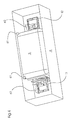
- Fig. 3
- die erfindungsgemäße Vorrichtung nach Fig. 2 mit in den Schutzbehälter eingeschobener Fixier-/Heizwalze oberhalb eines Transportbehälters,
- Fig. 4
- die erfindungsgemäße Vorrichtung nach Fig. 3 mit in den Transportbehälter eingelegtem, eine Fixier-/Heizwalze enthaltenden Schutzbehälter in einer räumlichen Darstellung von oben.
- L1
- erste Lagerstelle/n für 1.Walze (Fixier-/Heizwalze) in Fixiereinheit
- L2
- zweite Lagerstelle/n für 1.Walze (Fixier-/Heizwalze) in Fixiereinheit
- L3
- erste Lagerstelle/n für 2.Walze (Anpresswalze) in Fixiereinheit
- L4
- zweite Lagerstelle/n für 2.Walze (Anpresswalze) in Fixiereinheit
- F
- Fixiereinheit
- H
- Heizlampe der 1. Walze
- S
- Aufzeichnungsmedium /Blatt oder Band (Papier, Folie etc.)
- T1
- erster Tragegriff/e von Tragemittel der 1.Walze
- T2
- zweiter Tragegriff/e von Tragemittel der 1.Walze
- X1
- Mittenachse der 1.Walze
- X2
- Mittenachse der 2.Walze
- Y1
- Mittenachse von Lagerstelle für 1.Walze
- Y2
- Mittenachse von Lagerstelle für 2.Walze
- Z
- Schwenkachse der oberen und unteren Chassisteile der Fixiereinheit
- 1
- erste/obere Walze (Fixier-/Heizwalze) der Fixiereinheit
- 2
- zweite/untere Walze(Fixier-/Heizwalze) der Fixiereinheit
- 3
- Mittel zum Freigeben (Ent/Verriegeln) der Walzen in den Lagerstellen
- 4
- Mittel zum radialen Trennen (Aneinanderpressen) der Walzen in der Fixiereinheit
- 5
- Schutzbehälter / Handhabungsbehälter zum Aufstecken auf die Walzen
- 6
- Transportbehälter für die Walze/n mit Schutzbehälter
- 10
- Mittel an Tragegriff/en der 1.Walze zum axialen/radialen Zentrieren/Führen der 1. Walze in Lagerstellen von Fixiereinheit
- 11
- Mittel an Tragegriff/en der 1.Walze zum axialen/radialen Zentrieren/Führen des Schutzbehälters
- 30
- Ent/Verriegelungshebel der Freigabemittel an Lagerstellen
- 40
- Betätigungshebel der Trennmittel/Schwenkmittel für die Walzen
- 51
- Innenhohlraum des Schutzbehälters
- 52
- Freisparung/en in Seitenwand/wände des Schutzbehälters
- 53
- Seitenwand/wände des Schutzbehälters
- 61
- Lagesicherungsmittel für Schutzbehälter im Transportbehälter
- 62
- Lagesicherungsmittel für Walze im Transportbehälter
- 63
- Handgriff/e an Transportbehälter
Claims (16)
- Vorrichtung zum manuellen Austauschen und Transportieren einer Walze (1) eines Vervielfältigungsgerätes oder elektrographischen Druckers, wobei die Walze mit Tragemitteln ausgestattet ist,
dadurch gekennzeichnet, dass ein Schutzbehälter (5) vorgesehen ist, der über eine im Gerät freigegebene Walze (1) und deren Tragemittel (T1;T2) stülpbar ist; und die Walze (1) zusammen mit dem Schutzbehälter (5) mittels ihrer aus dem Schutzbehälter herausragenden Tragemittel (T1;T2) aus dem Vervielfältigungsgerät bzw. Drucker entnehmbar und in dieses einsetzbar ist. - Vorrichtung nach Anspruch 1,
dadurch gekennzeichnet, dass der Schutzbehälter (5) ein im wesentlichen U-förmiges Querschnittsprofil aufweist, dessen Innenhohlraum (51) zur Aufnahme einer Walze (1) einen Durchmesser hat, der größer als der eines Außendurchmessers der Walze ist, derart, dass bei auf die Tragemittel der Walze aufgestecktem Schutzbehälter keine Berührung zwischen dem Schutzbehälter und der Walze stattfindet. - Vorrichtung nach Anspruch 1,
dadurch gekennzeichnet, dass der Schutzbehälter (5) Freisparungen (52) in seiner Behälterwand (53) zur Aufnahme der Tragemittel (T1;T2) der Walze aufweist, deren lichte, innere Weite gegenüber einem zugeordneten Außendurchmesser der Tragemittel derart vorbestimmt ist, das der Schutzbehälter mit seinen Freisparungen auf den Tragemitteln klemmend angeordnet ist. - Austauschbare Walze für ein Vervielfältigungsgerät bzw. einen elektrophotographischer Drucker
dadurch gekennzeichnet, dass die Walze (1), die an ihren beiden axialen Enden jeweils einen Tragegriff (T1;T2) als Tragemittel aufweist, mittels denen die Walze in an den Lagerstellen (L1;L2) des Gerätes angeordneten, radial vom Außenumfang zur Mittenachse (Yl) der Lagerstellen verlaufenden, im wesentlichen schlitzförmigen Öffnungen führbar, radial in die Lagerstellen einsetzbar und aus ihnen entnehmbar ist. - Walze nach Anspruch 4,
dadurch gekennzeichnet, dass die Tragegriffe (T1;T2) zentrisch zur axialen Mittenachse (X1) an den Enden der Walze (1) angeordnet sind; und die Tragegriffe der Walze über Lagerstellen (L1;L2) des Gerätes axial hinausragen. - Walze nach Anspruch 5,
dadurch gekennzeichnet, dass die beiden Tragegriffe (T1;T2) der Walze (1) Mittel (10) zum axialen und radialen Zentrieren, Führen und Halten der Walze in ihren Lagerstellen (L1;L2) im Gerät aufweisen; die beiden Tragegriffe der Walze (1) Mittel (11) zum axialen und radialen Zentrieren, Führen und Halten des Schutzbehälters (5) auf der Walze aufweisen; und die Tragegriffe (T1;T2) in Form von im wesentlichen eckigen, runden oder ovalen Henkeln, Ösen oder Knäufen ausgebildet sind. - Walze nach Anspruch 6,
dadurch gekennzeichnet, dass die Mittel (10;11) zum axialen und radialen Zentrieren und Führen der Walze (1) in den Lagerstellen (L1;L2) des Gerätes und in den Freisparungen (52) des Schutzbehälters (5) zusammengefasst und einstückig ausgebildet an den Tragegriffen angeordnet sind. - Vervielfältigungsgerät bzw. elektrophotographischer Drucker mit einer austauschbaren Walze nach einem der Ansprüche 4 bis 7.
- Vorrichtung zum manuellen Austauschen und Transportieren für eine Walze nach Anspruch 7,
dadurch gekennzeichnet, dass der Schutzbehälter (5) an seinen beiden axial angeordneten Seitenwänden (53) jeweils im wesentlichen schlitzförmige Freisparungen (52) zur Aufnahme von den an den axialen Enden der Walze (1) angeordneten Zentrier/Führungs-Mitteln (11) der Tragegriffen (T1;T2) aufweist; und dass die lichte innere Weite der Freisparungen (52) gegenüber den zugeordneten Außendurchmessern der Zentrier/Führungs-Mittel (11) derart angepasst ist, das der Schutzbehälter (5) mit seinen Seitenwänden (53) darauf klemmend angeordnet ist. - Vorrichtung nach Anspruch 9,
dadurch gekennzeichnet, dass die schlitzförmigen Freisparungen (52) für die Mittel (11) an den Seitenwänden (53) des Schutzbehälters (5) zentrisch zur axialen Mittenachse des Innenhohlraumes des U-förmigen Schutzbehälters angeordnet sind; und die Freisparungen und der Innenhohlraum zum Aufstecken und Entnehmen des Schutzbehälters auf/von die/der Walze (1) gleiche Ausrichtungen aufweisen. - Transportbehälter für eine austauschbare Waklze,
dadurch gekennzeichnet, dass die Walze (1) manuell einlegbar und entnehmbar ist, und dass in dem Transportbehälter Mittel (61; 62) zur Lagesicherung der Walze angeordnet sind. - Transportbehälter für eine austauschbare Walze;
dadurch gekennzeichnet, dass der mit einer Walze (1) bestückte Schutzbehälter (5) manuell einlegbar und entnehmbar ist, wobei im Transportbehälter Mittel (61;62) zur Lagesicherung des Schutzbehälters und der Walze angeordnet sind. - Transportbehälter nach Anspruch 12,
dadurch gekennzeichnet, dass Mittel (62) zur Lagesicherung der Walze (1) an den Tragegriffen (T1;T2) angreifen und gegen Mittel (61) zur Lagesicherung des Schutzbehälters (5) wirken; und die Mittel (61;62) zur Lagesicherung der Walze und des Schutzbehälters federelastisch ausgebildet sind. - Transportbehälter nach Anspruch 12 oder 13,
dadurch gekennzeichnet, dass er mehrere Lagesicherungsmittel (61;62) zur Aufnahme mehrerer Walzen (1) mit Schutzbehälter (5) aufweist; und der Transportbehälter zwei Handgriffe (63) aufweist - Vorrichtung nach Anspruch 1
dadurch gekennzeichnet, dass der Schutzbehälter (5) aus einem federelastischen, thermisch beständigen und isolierenden Kunststoffmaterial besteht. - Gerät nach Anspruch 8,
dadurch gekennzeichnet, dass die Walzen (1) als Fixier-, Heiz-, Anpress-, Bild-Transfer- oder Blatt-Förderwalzen ausgebildet sind.
Applications Claiming Priority (2)
| Application Number | Priority Date | Filing Date | Title |
|---|---|---|---|
| DE10023715A DE10023715A1 (de) | 2000-05-17 | 2000-05-17 | Vorrichtung zum manuellen Austauschen und Transportieren einer Walze eines Vervielfältigungsgerätes |
| DE10023715 | 2000-05-17 |
Publications (3)
| Publication Number | Publication Date |
|---|---|
| EP1156397A2 true EP1156397A2 (de) | 2001-11-21 |
| EP1156397A3 EP1156397A3 (de) | 2005-01-26 |
| EP1156397B1 EP1156397B1 (de) | 2007-07-25 |
Family
ID=7642088
Family Applications (1)
| Application Number | Title | Priority Date | Filing Date |
|---|---|---|---|
| EP01110024A Expired - Lifetime EP1156397B1 (de) | 2000-05-17 | 2001-04-26 | Vorrichtung zum manuellen Austauschen und Transportieren einer Heizwalze eines Vervielfältigungsgerätes bzw. eines elektrophotographischen Druckers |
Country Status (4)
| Country | Link |
|---|---|
| US (1) | US6490425B2 (de) |
| EP (1) | EP1156397B1 (de) |
| AT (1) | ATE368243T1 (de) |
| DE (2) | DE10023715A1 (de) |
Families Citing this family (2)
| Publication number | Priority date | Publication date | Assignee | Title |
|---|---|---|---|---|
| US6785493B2 (en) | 2002-07-11 | 2004-08-31 | Hewlett-Packard Development Company, L.P. | User-replaceable fuser cartridge for electrophotographic printing systems |
| JP5493921B2 (ja) * | 2010-01-29 | 2014-05-14 | 株式会社リコー | 定着装置のローラ交換補助具 |
Family Cites Families (15)
| Publication number | Priority date | Publication date | Assignee | Title |
|---|---|---|---|---|
| US3888577A (en) * | 1973-02-12 | 1975-06-10 | Xerox Corp | Apparatus for packaging and subsequently installing a belt onto a roller assembly |
| JPS59111672A (ja) * | 1982-12-17 | 1984-06-27 | Fuji Electric Co Ltd | 電子写真用感光体の梱包方法 |
| US4888620A (en) * | 1986-01-17 | 1989-12-19 | Canon Kabushiki Kaisha | Process cartridge and image forming apparatus using the same |
| GB2189327A (en) * | 1986-04-15 | 1987-10-21 | Xerox Corp | Copier having readily replacable photoconductive member |
| JPS63146086A (ja) * | 1986-12-10 | 1988-06-18 | Toshiba Corp | 記録装置 |
| US5239349A (en) * | 1992-01-31 | 1993-08-24 | Eastman Kodak Company | Fuser and a fuser roller cartridge having fusing roller skive |
| JPH06507029A (ja) * | 1992-01-31 | 1994-08-04 | イーストマン・コダック・カンパニー | 融着装置及び融着装置用の融着ローラカートリッジ |
| JPH06186895A (ja) * | 1992-12-16 | 1994-07-08 | Ricoh Co Ltd | 梱包箱 |
| US5481350A (en) * | 1993-04-12 | 1996-01-02 | Ricoh Company, Ltd. | Heat roller fixing device divided into first and second frames and with positioning members of the first frame |
| US6249661B1 (en) * | 1993-12-08 | 2001-06-19 | Ricoh Company, Ltd. | Device for supporting an image carrier included in an image forming apparatus |
| DE4443764B4 (de) * | 1993-12-08 | 2004-09-30 | Ricoh Co., Ltd. | Anordnung zum Halten eines Bildträgers |
| US5842085A (en) * | 1996-07-09 | 1998-11-24 | Mita Industrial Co., Ltd. | Fixing device in an image forming machine having reduced thermal fatigue |
| US6048676A (en) * | 1997-12-04 | 2000-04-11 | Agfa-Gevaert | Light-tight package for a roll of light-sensitive material |
| US6285845B1 (en) * | 1999-05-11 | 2001-09-04 | Zih Corp. | Card cleaning device and method of use |
| US6295427B1 (en) * | 1999-12-29 | 2001-09-25 | Nex Press Solutions Llc | Protective container/installation fixture for image-recording/image-transfer drums |
-
2000
- 2000-05-17 DE DE10023715A patent/DE10023715A1/de not_active Withdrawn
-
2001
- 2001-04-26 EP EP01110024A patent/EP1156397B1/de not_active Expired - Lifetime
- 2001-04-26 DE DE50112755T patent/DE50112755D1/de not_active Expired - Lifetime
- 2001-04-26 AT AT01110024T patent/ATE368243T1/de not_active IP Right Cessation
- 2001-05-07 US US09/850,513 patent/US6490425B2/en not_active Expired - Fee Related
Also Published As
| Publication number | Publication date |
|---|---|
| ATE368243T1 (de) | 2007-08-15 |
| EP1156397A3 (de) | 2005-01-26 |
| EP1156397B1 (de) | 2007-07-25 |
| DE10023715A1 (de) | 2001-11-22 |
| DE50112755D1 (de) | 2007-09-06 |
| US6490425B2 (en) | 2002-12-03 |
| US20020025189A1 (en) | 2002-02-28 |
Similar Documents
| Publication | Publication Date | Title |
|---|---|---|
| DE60216705T2 (de) | Einheit und elektrophotografischer Bilderzeugungsapparat | |
| DE3425953A1 (de) | Druckgeraet | |
| DE69413935T2 (de) | Übertragungsbandkassette für einen Wärmeübertragungsdrucker | |
| DE69925951T2 (de) | Fixiergerät und Bilderzeugungsgerät | |
| DE69010710T2 (de) | Bilderzeugungsgerät. | |
| DE2352171C2 (de) | Ein- und Ausgabevorrichtung für ein Kopiergerät | |
| DE69107501T2 (de) | Vorrichtung zum Aufwickeln von Dokumenten. | |
| DE2817300C2 (de) | Elektrofotografisches Kopiergerät mit einer austauschbaren endlichen Fotoleiterbahn | |
| DE4300939A1 (en) | Paper transport system for image prodn. unit esp. copier - has three rollers and three surface parts for closing three guide plates to make pressure contact so that paper can be transported and plates opened for paper release | |
| EP1156397B1 (de) | Vorrichtung zum manuellen Austauschen und Transportieren einer Heizwalze eines Vervielfältigungsgerätes bzw. eines elektrophotographischen Druckers | |
| EP1156396B1 (de) | Vorrichtung zum manuellen Austauschen einer Walze eines Viervielfältigungsgerätes | |
| EP0280949B1 (de) | Wickelträger zum Zwischenspeichern von aufgewickelten Druckereierzeugnissen wie Zeitungen, Zeitschriften und dergleichen | |
| DE3502535A1 (de) | Bilderzeugungsgeraet | |
| DE3153658C2 (de) | Bildaufzeichnungsger{t | |
| DE4443764B4 (de) | Anordnung zum Halten eines Bildträgers | |
| DE2653519B1 (de) | Reinigungseinrichtung fuer die Fixierwalze eines Druckfixierwalzenpaares in einem elektrostatischen Kopiergeraet | |
| DE10163419A1 (de) | Fixierer-Bandreinigungsbaugruppe für eine elektrofotografische Vorrichtung | |
| DE4214126C2 (de) | Elektrofotografisches Gerät | |
| DE3515610C1 (de) | Andrueckrolle fuer ein Etikettiergeraet | |
| DE2245573C3 (de) | Haltevorrichtung für eine Rolle von fotografischem Kopiermaterial | |
| DE3604915A1 (de) | Papierfuehrungsvorrichtung fuer einen drucker | |
| DE10301809A1 (de) | Vorrichtung zum Ein- und Ausbauen einer Walze für einen elektrostatografischen Drucker/Kopierer | |
| EP1155836B1 (de) | Vorrichtung zum Zuführen einer Druckplatte zu einem Plattenzylinder einer Druckmaschine | |
| DE69803959T2 (de) | Führungsmechanismus für Papierrolle und Führungsgerät für Papiermagazin | |
| DE9314937U1 (de) | Umdruckstation mit Andruckelement für ein elektrografisches Druck- oder Kopiergerät |
Legal Events
| Date | Code | Title | Description |
|---|---|---|---|
| PUAI | Public reference made under article 153(3) epc to a published international application that has entered the european phase |
Free format text: ORIGINAL CODE: 0009012 |
|
| AK | Designated contracting states |
Kind code of ref document: A2 Designated state(s): AT BE CH CY DE DK ES FI FR GB GR IE IT LI LU MC NL PT SE TR |
|
| AX | Request for extension of the european patent |
Free format text: AL;LT;LV;MK;RO;SI |
|
| RAP1 | Party data changed (applicant data changed or rights of an application transferred) |
Owner name: EASTMAN KODAK COMPANY |
|
| PUAL | Search report despatched |
Free format text: ORIGINAL CODE: 0009013 |
|
| AK | Designated contracting states |
Kind code of ref document: A3 Designated state(s): AT BE CH CY DE DK ES FI FR GB GR IE IT LI LU MC NL PT SE TR |
|
| AX | Request for extension of the european patent |
Extension state: AL LT LV MK RO SI |
|
| 17P | Request for examination filed |
Effective date: 20050604 |
|
| AKX | Designation fees paid |
Designated state(s): AT BE CH CY DE DK ES FI FR GB GR IE IT LI LU MC NL PT SE TR |
|
| GRAP | Despatch of communication of intention to grant a patent |
Free format text: ORIGINAL CODE: EPIDOSNIGR1 |
|
| RTI1 | Title (correction) |
Free format text: DEVICE FOR MANUALLY EXCHANGING AND TRANSPORTING A HEATING ROLL OF A REPRODUCTION APPARATUS FOR EXAMPLE AN ELECTROPHOTOGRAPHIC PRINTER |
|
| GRAS | Grant fee paid |
Free format text: ORIGINAL CODE: EPIDOSNIGR3 |
|
| GRAA | (expected) grant |
Free format text: ORIGINAL CODE: 0009210 |
|
| AK | Designated contracting states |
Kind code of ref document: B1 Designated state(s): AT BE CH CY DE DK ES FI FR GB GR IE IT LI LU MC NL PT SE TR |
|
| REG | Reference to a national code |
Ref country code: GB Ref legal event code: FG4D Free format text: NOT ENGLISH |
|
| RIN1 | Information on inventor provided before grant (corrected) |
Inventor name: SCHMIDT, PETER Inventor name: KONDAY, ANDREAS Inventor name: WEBER, MARKUS |
|
| GBT | Gb: translation of ep patent filed (gb section 77(6)(a)/1977) |
Effective date: 20070725 |
|
| REG | Reference to a national code |
Ref country code: CH Ref legal event code: EP |
|
| REG | Reference to a national code |
Ref country code: IE Ref legal event code: FG4D Free format text: LANGUAGE OF EP DOCUMENT: GERMAN |
|
| REF | Corresponds to: |
Ref document number: 50112755 Country of ref document: DE Date of ref document: 20070906 Kind code of ref document: P |
|
| PG25 | Lapsed in a contracting state [announced via postgrant information from national office to epo] |
Ref country code: FI Free format text: LAPSE BECAUSE OF FAILURE TO SUBMIT A TRANSLATION OF THE DESCRIPTION OR TO PAY THE FEE WITHIN THE PRESCRIBED TIME-LIMIT Effective date: 20070725 Ref country code: NL Free format text: LAPSE BECAUSE OF FAILURE TO SUBMIT A TRANSLATION OF THE DESCRIPTION OR TO PAY THE FEE WITHIN THE PRESCRIBED TIME-LIMIT Effective date: 20070725 Ref country code: ES Free format text: LAPSE BECAUSE OF FAILURE TO SUBMIT A TRANSLATION OF THE DESCRIPTION OR TO PAY THE FEE WITHIN THE PRESCRIBED TIME-LIMIT Effective date: 20071105 Ref country code: PT Free format text: LAPSE BECAUSE OF FAILURE TO SUBMIT A TRANSLATION OF THE DESCRIPTION OR TO PAY THE FEE WITHIN THE PRESCRIBED TIME-LIMIT Effective date: 20071226 |
|
| NLV1 | Nl: lapsed or annulled due to failure to fulfill the requirements of art. 29p and 29m of the patents act | ||
| REG | Reference to a national code |
Ref country code: IE Ref legal event code: FD4D |
|
| EN | Fr: translation not filed | ||
| PG25 | Lapsed in a contracting state [announced via postgrant information from national office to epo] |
Ref country code: GR Free format text: LAPSE BECAUSE OF FAILURE TO SUBMIT A TRANSLATION OF THE DESCRIPTION OR TO PAY THE FEE WITHIN THE PRESCRIBED TIME-LIMIT Effective date: 20071026 Ref country code: DK Free format text: LAPSE BECAUSE OF FAILURE TO SUBMIT A TRANSLATION OF THE DESCRIPTION OR TO PAY THE FEE WITHIN THE PRESCRIBED TIME-LIMIT Effective date: 20070725 |
|
| PG25 | Lapsed in a contracting state [announced via postgrant information from national office to epo] |
Ref country code: IE Free format text: LAPSE BECAUSE OF FAILURE TO SUBMIT A TRANSLATION OF THE DESCRIPTION OR TO PAY THE FEE WITHIN THE PRESCRIBED TIME-LIMIT Effective date: 20070725 |
|
| PLBE | No opposition filed within time limit |
Free format text: ORIGINAL CODE: 0009261 |
|
| STAA | Information on the status of an ep patent application or granted ep patent |
Free format text: STATUS: NO OPPOSITION FILED WITHIN TIME LIMIT |
|
| PG25 | Lapsed in a contracting state [announced via postgrant information from national office to epo] |
Ref country code: SE Free format text: LAPSE BECAUSE OF FAILURE TO SUBMIT A TRANSLATION OF THE DESCRIPTION OR TO PAY THE FEE WITHIN THE PRESCRIBED TIME-LIMIT Effective date: 20071025 |
|
| 26N | No opposition filed |
Effective date: 20080428 |
|
| PG25 | Lapsed in a contracting state [announced via postgrant information from national office to epo] |
Ref country code: FR Free format text: LAPSE BECAUSE OF FAILURE TO SUBMIT A TRANSLATION OF THE DESCRIPTION OR TO PAY THE FEE WITHIN THE PRESCRIBED TIME-LIMIT Effective date: 20080321 |
|
| BERE | Be: lapsed |
Owner name: EASTMAN KODAK CY Effective date: 20080430 |
|
| PG25 | Lapsed in a contracting state [announced via postgrant information from national office to epo] |
Ref country code: MC Free format text: LAPSE BECAUSE OF NON-PAYMENT OF DUE FEES Effective date: 20080430 |
|
| REG | Reference to a national code |
Ref country code: CH Ref legal event code: PL |
|
| PG25 | Lapsed in a contracting state [announced via postgrant information from national office to epo] |
Ref country code: LI Free format text: LAPSE BECAUSE OF NON-PAYMENT OF DUE FEES Effective date: 20080430 Ref country code: CH Free format text: LAPSE BECAUSE OF NON-PAYMENT OF DUE FEES Effective date: 20080430 |
|
| PG25 | Lapsed in a contracting state [announced via postgrant information from national office to epo] |
Ref country code: BE Free format text: LAPSE BECAUSE OF NON-PAYMENT OF DUE FEES Effective date: 20080430 |
|
| PG25 | Lapsed in a contracting state [announced via postgrant information from national office to epo] |
Ref country code: CY Free format text: LAPSE BECAUSE OF FAILURE TO SUBMIT A TRANSLATION OF THE DESCRIPTION OR TO PAY THE FEE WITHIN THE PRESCRIBED TIME-LIMIT Effective date: 20070725 |
|
| PG25 | Lapsed in a contracting state [announced via postgrant information from national office to epo] |
Ref country code: AT Free format text: LAPSE BECAUSE OF NON-PAYMENT OF DUE FEES Effective date: 20080426 |
|
| PG25 | Lapsed in a contracting state [announced via postgrant information from national office to epo] |
Ref country code: LU Free format text: LAPSE BECAUSE OF NON-PAYMENT OF DUE FEES Effective date: 20080426 |
|
| PG25 | Lapsed in a contracting state [announced via postgrant information from national office to epo] |
Ref country code: TR Free format text: LAPSE BECAUSE OF FAILURE TO SUBMIT A TRANSLATION OF THE DESCRIPTION OR TO PAY THE FEE WITHIN THE PRESCRIBED TIME-LIMIT Effective date: 20070725 |
|
| PG25 | Lapsed in a contracting state [announced via postgrant information from national office to epo] |
Ref country code: IT Free format text: LAPSE BECAUSE OF NON-PAYMENT OF DUE FEES Effective date: 20080430 |
|
| PGFP | Annual fee paid to national office [announced via postgrant information from national office to epo] |
Ref country code: GB Payment date: 20130326 Year of fee payment: 13 |
|
| PGFP | Annual fee paid to national office [announced via postgrant information from national office to epo] |
Ref country code: DE Payment date: 20130430 Year of fee payment: 13 |
|
| REG | Reference to a national code |
Ref country code: DE Ref legal event code: R119 Ref document number: 50112755 Country of ref document: DE |
|
| GBPC | Gb: european patent ceased through non-payment of renewal fee |
Effective date: 20140426 |
|
| PG25 | Lapsed in a contracting state [announced via postgrant information from national office to epo] |
Ref country code: GB Free format text: LAPSE BECAUSE OF NON-PAYMENT OF DUE FEES Effective date: 20140426 Ref country code: DE Free format text: LAPSE BECAUSE OF NON-PAYMENT OF DUE FEES Effective date: 20141101 |
|
| REG | Reference to a national code |
Ref country code: DE Ref legal event code: R119 Ref document number: 50112755 Country of ref document: DE Effective date: 20141101 |