EP1155834A2 - Vorrichtung zum Entfernen elektrischer Ladungen von flachem Material - Google Patents
Vorrichtung zum Entfernen elektrischer Ladungen von flachem Material Download PDFInfo
- Publication number
- EP1155834A2 EP1155834A2 EP01110025A EP01110025A EP1155834A2 EP 1155834 A2 EP1155834 A2 EP 1155834A2 EP 01110025 A EP01110025 A EP 01110025A EP 01110025 A EP01110025 A EP 01110025A EP 1155834 A2 EP1155834 A2 EP 1155834A2
- Authority
- EP
- European Patent Office
- Prior art keywords
- metal plates
- flow channel
- openings
- brush
- carriers
- Prior art date
- Legal status (The legal status is an assumption and is not a legal conclusion. Google has not performed a legal analysis and makes no representation as to the accuracy of the status listed.)
- Withdrawn
Links
- 239000000463 material Substances 0.000 title claims description 4
- 239000002184 metal Substances 0.000 claims abstract description 33
- 239000000969 carrier Substances 0.000 claims description 9
- 210000002105 tongue Anatomy 0.000 claims description 6
- 150000002500 ions Chemical class 0.000 claims description 5
- 229920000049 Carbon (fiber) Polymers 0.000 claims description 3
- 239000004917 carbon fiber Substances 0.000 claims description 3
- 229910001220 stainless steel Inorganic materials 0.000 claims description 3
- 239000010935 stainless steel Substances 0.000 claims description 3
- 239000000835 fiber Substances 0.000 claims description 2
- 238000007599 discharging Methods 0.000 abstract 1
- 230000015572 biosynthetic process Effects 0.000 description 4
- 239000011888 foil Substances 0.000 description 2
- 229910000831 Steel Inorganic materials 0.000 description 1
- 230000000694 effects Effects 0.000 description 1
- 230000005684 electric field Effects 0.000 description 1
- 230000007613 environmental effect Effects 0.000 description 1
- VNWKTOKETHGBQD-UHFFFAOYSA-N methane Chemical compound C VNWKTOKETHGBQD-UHFFFAOYSA-N 0.000 description 1
- 238000000034 method Methods 0.000 description 1
- 239000010959 steel Substances 0.000 description 1
Images

Classifications
-
- G—PHYSICS
- G03—PHOTOGRAPHY; CINEMATOGRAPHY; ANALOGOUS TECHNIQUES USING WAVES OTHER THAN OPTICAL WAVES; ELECTROGRAPHY; HOLOGRAPHY
- G03G—ELECTROGRAPHY; ELECTROPHOTOGRAPHY; MAGNETOGRAPHY
- G03G15/00—Apparatus for electrographic processes using a charge pattern
- G03G15/65—Apparatus which relate to the handling of copy material
-
- B—PERFORMING OPERATIONS; TRANSPORTING
- B65—CONVEYING; PACKING; STORING; HANDLING THIN OR FILAMENTARY MATERIAL
- B65H—HANDLING THIN OR FILAMENTARY MATERIAL, e.g. SHEETS, WEBS, CABLES
- B65H5/00—Feeding articles separated from piles; Feeding articles to machines
-
- B—PERFORMING OPERATIONS; TRANSPORTING
- B65—CONVEYING; PACKING; STORING; HANDLING THIN OR FILAMENTARY MATERIAL
- B65H—HANDLING THIN OR FILAMENTARY MATERIAL, e.g. SHEETS, WEBS, CABLES
- B65H2301/00—Handling processes for sheets or webs
- B65H2301/50—Auxiliary process performed during handling process
- B65H2301/51—Modifying a characteristic of handled material
- B65H2301/513—Modifying electric properties
- B65H2301/5133—Removing electrostatic charge
-
- G—PHYSICS
- G03—PHOTOGRAPHY; CINEMATOGRAPHY; ANALOGOUS TECHNIQUES USING WAVES OTHER THAN OPTICAL WAVES; ELECTROGRAPHY; HOLOGRAPHY
- G03G—ELECTROGRAPHY; ELECTROPHOTOGRAPHY; MAGNETOGRAPHY
- G03G2215/00—Apparatus for electrophotographic processes
- G03G2215/00362—Apparatus for electrophotographic processes relating to the copy medium handling
- G03G2215/00535—Stable handling of copy medium
- G03G2215/00649—Electrodes close to the copy feeding path
-
- G—PHYSICS
- G03—PHOTOGRAPHY; CINEMATOGRAPHY; ANALOGOUS TECHNIQUES USING WAVES OTHER THAN OPTICAL WAVES; ELECTROGRAPHY; HOLOGRAPHY
- G03G—ELECTROGRAPHY; ELECTROPHOTOGRAPHY; MAGNETOGRAPHY
- G03G2215/00—Apparatus for electrophotographic processes
- G03G2215/00362—Apparatus for electrophotographic processes relating to the copy medium handling
- G03G2215/00535—Stable handling of copy medium
- G03G2215/00654—Charging device
Definitions
- the invention relates to a device for removing electrical charges from flat Material created by a flow channel made of grounded metal plates is transported, in particular by pressure carriers when passing through the transport tracks of printing or copying machines.
- Print media such as sheets of paper, foils or the like Transport lanes of printing and copying machines are electrically charged. In order to prevent printed sheets of paper or foils from jamming together in the output tray must adhere to sufficient electrically conductive components of the transport track these electrical landings are removed.
- the invention has for its object to provide a device with electrical charges from print media, electrophotographic copying machines or Go through printing presses, are reliably removable.
- the Task solved to remove surface charges that are in opposite Polarity are located on the top and bottom of a print carrier, so-called Charge double layers.
- the unloading devices consist of passive means and / or active ones Means that are transverse to the transport direction of the print medium over the entire width of the Extend flow channel.
- Expedient are as active discharge devices with alternating high voltage Operated ionization bars provided, which are equally spaced along a straight line Line have ionizer tips that are aligned perpendicular to the flow channel.
- passive discharge devices are formed from carbon fibers or stainless steel fibers Brushes provided.
- the device according to the invention is designed so that the Flow channel for the metal plates forming the pressure carrier in the area of each Ionizer tip of an unloading device have an opening to the flow channel, such that when the ionizing rod is activated, the ions generated enter the flow channel or get to the print carrier.
- the openings can be round, square or are rectangular.
- the openings are elongated slots formed, which are formed between tongues machined from the metal plates.
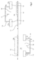
- the metal plates 12 and 13 are, for example from one (1) millimeter thick sheet steel, which is about three (3) millimeters high Limit flow channel 14.
- Ionization bars 15 and 16 extend transversely to the transport direction of the print carrier 11 over the entire width of the flow channel 14 and have regular intervals of ten (10) millimeters lying on a straight line ionizer tips 17, the are aligned perpendicular to the flow channel 14.
- each ionizer tip 17 is an opening 18 in the metal plates 12 and 13 provided that the ions generated the passage from the ionizer tip 17 to Enable flow channel 14 and thus to the print carrier 11.
- Reality rectilinear flow channel 14 shown drawn off to one to obtain straight-line transport of the print carrier 11.
- the ionizing bars 15 and 16 are arranged one after the other in the transport direction of the print carrier 11.
- Print carrier 11 rests on the metal plate 13.
- the free ionizing bar 15 positive charge sitting on the facing surface is removed by means of the ionizer tips 17 compensated. Due to the remaining negative charge on the bottom of the Print carrier 11 lies against the metal plate 12 with the discharged surface and the negative is compensated by the downstream ionizing bar 16.
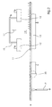
- FIG. 2 shows a less expensive variant, in which the Ionization bar 16 by a passive discharge device in the form of a brush 19 is replaced.
- the current charge lies with electrical charge provided print carrier 11 on the metal plate 13 and its positive charge on the The upper side is compensated for by means of the ionizing bar 15. Then the Print carrier 11 with the discharged surface on the metal plate 12.
- the lower metal plate 13 ends in front of the brush 19 in an edge 20. This causes the negative charge on the underside of the print carrier 14 in a on the edge 20th trained ionizer zone is largely removed. The remaining one, if any Residual charge is then diverted by means of the brush 19.
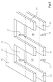
- the formation and arrangement of the openings 18 in the metal plates 12 and 13 can be met in different ways. It is important that the greatest possible distance between the ionizer tips 17 and the edge of the openings formed by the There is a metal plate on which the ionization bars 15 and 16 are seated in a conductive manner.
- the openings 18 are formed as round openings 18 'and are in the Metal plates 12 and 13 are arranged flush opposite one another.
- the openings are also designed as round openings 18 '. They are however, by the distance a / 2 of the distance between two ionizer tips 17 or two Adjacent openings offset transversely to the transport direction of a print medium arranged.
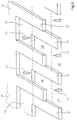
- openings 5 shows a variant of the formation of the openings.
- the openings are at the end of the metal plates 12 and 13 as slot openings 18 "between tongues 1 educated.
Landscapes
- Physics & Mathematics (AREA)
- General Physics & Mathematics (AREA)
- Engineering & Computer Science (AREA)
- Mechanical Engineering (AREA)
- Elimination Of Static Electricity (AREA)
- Feeding Of Articles By Means Other Than Belts Or Rollers (AREA)
- Accessory Devices And Overall Control Thereof (AREA)
Abstract
Description
- Fig. 1
- die erfindungsgemäße Vorrichtung in einer Ausführung mit zwei aktiven Entladungsvorrichtungen in schematischer Darstellung,
- Fig. 2
- die erfindungsgemäße Vorrichtung in einer Ausführung mit einer aktiven und einer passiven Entladungsvorrichtung in schematischer Darstellung,
- Fig. 3
- die Ausbildung und Anordnung der Öffnungen für die Ionisatorspitzen in den Metallplatten der erfindungsgemäßen Vorrichtung in schematischer Darstellung,
- Fig. 4
- eine Variante in der Anordnung der Öffnungen gemäß Fig. 3 in schematischer Darstellung,
- Fig. 5
- eine Variante der Ausbildung der Öffnungen gemäß Fig. 3 in schematischer Darstellung und
- Fig. 6
- eine Variante der Anordnung der Öffnungen gemäß Fig. 5 in schematischer Darstellung.
- 11
- Druckträger
- 12
- Metallplatte (oben)
- 13
- Metallplatte (unten)
- 14
- Durchlaufkanal
- 15
- Ionisationsstab (oben)
- 16
- Ionisationsstab (unten)
- 17
- Ionisatorspitze
- 18
- Öffnung 18' Rundöffung 18" Schlitzöffnung
- 19
- Bürste
- 20
- Kante
- 21
- Zunge
Claims (12)
- Vorrichtung zum Entfernen elektrischer Ladungen von flachem Material, das durch einen aus geerdeten Metallplatten gebildeten Durchlaufkanal transportiert wird, insbesondere von Druckträgern beim Durchlaufen der Transportbahnen von Druck- bzw. Kopiermaschinen,
dadurch gekennzeichnet, dass auf den vom Durchlaufkanal (14) abgekehrten Außenflächen der Metallplatten 12 und 13) jeweils mindestens eine Entladungsvorrichtung (15; 16; 19) quer zur Transportrichtung der Druckträger (11) angeordnet ist und dass die Entladungsvorrichtungen im wesentlichen sich gegenüberliegend bzw. in Transportrichtung der Druckträger gegeneinander versetzt angeordnet sind. - Vorrichtung nach Anspruch 1,
dadurch gekennzeichnet, dass die Entladevorrichtungen (15; 16; 19) aus passiven Mitteln und/oder aus aktiven Mitteln bestehen, die sich quer zur Transportrichtung der Druckträger (11) über die gesamte Breite des Durchlaufkanals erstrecken. - Vorrichtung nach den Ansprüchen 1 oder 2,
dadurch gekennzeichnet, dass als aktive Entladevorrichtungen mit Wechselhochspannung betriebene Ionisationsstäbe (15 und 16) vorgesehen sind, die in gleichen Abständen entlang einer geraden Linie Ionisatorspitzen(17) aufweisen, die lotrecht zum Durchlaufkanal 14) ausgerichtet sind. - Vorrichtung nach den Ansprüchen 1 oder 2,
dadurch gekennzeichnet, dass als passive Entladungsvorrichtungen aus Kohlefasern oder Edelstahlfasern gebildete Bürsten (19) vorgesehen sind. - Vorrichtung nach einem der Ansprüche bis 4,
dadurch gekennzeichnet, dass die den Durchlaufkanal (14) für die Druckträger (11) bildenden Metallplatten 12 und 13) im Bereich jeder Ionisatorspitze (17) einer Entladevorrichtung (15, 16) eine Öffnung zum Durchlaufkanal (14) aufweisen, derart, dass bei aktiviertem Ionisationsstab die erzeugten Ionen in den Durchlaufkanal (14) zu dem Druckträger 11) gelangen. - Vorrichtung nach Anspruch 5,
dadurch gekennzeichnet, dass die Öffnungen (18) rund, quadratisch oder rechteckförmig ausgebildet sind. - Vorrichtung nach Anspruch 5,
dadurch gekennzeichnet, dass die Öffnungen als längliche Schlitzöffnungen (18") ausgebildet sind, die zwischen aus den Metallplatten (12, 13) herausgearbeiteten Zungen (21) gebildet sind. - Vorrichtung nach einem der Ansprüche 1 bis 7,
dadurch gekennzeichnet, dass die Ionisatorspitzen (17) der sich gegenüberliegenden Entladevorrichtungen 15 und 16) sowie die ihnen zugeordneten Öffnungen (18, 18', 18") in den Metallplatten (12 und 13) fluchtend gegenüberliegend angeordnet sind. - Vorrichtung nach einem der Ansprüche 1 bis 7,
dadurch gekennzeichnet, dass die Ionisatorspitzen (17) der sich gegenüberliegenden Entladevorrichtungen (15 und 16) sowie die ihnen zugeordneten Öffnungen (18, 18', 18") in den Metallplatten (12 und 13) um den halben Abstand (a/2) zwischen zwei Ionisatorspitzen (17) quer zur Transportrichtung der Druckträger (11) gegeneinander versetzt angeordnet sind. - Vorrichtung nach einem der Ansprüche 1 bis 4,
dadurch gekennzeichnet, dass die sich gegenüberliegenden auf den Metallplatten (12 und 13) sitzenden Entladungsvorrichtungen (15, 16, 19) in Transportrichtung der Druckträger (11) gegeneinander versetzt angeordnet sind. - Vorrichtung nach einem der Ansprüche 1 bis 4,
dadurch gekennzeichnet, dass auf der einen Metallplatte (12) ein Ionisationsstab (15) als aktive Entladevorrichtung und auf der anderen Metallplatte (13) in Transportrichtung der Druckträger (11) versetzt eine Bürste (19) als passive Entladungsvorrichtung angeordnet ist. - Vorrichtung nach Anspruch 12,
dadurch gekennzeichnet, dass die Metallplatte, auf der passive Entladungsvorrichtung in Form einer Bürste angeordnet ist, im Bereich der Bürste (19) eine Aussparung zum Durchlaufkanal (14) aufweist bzw. in Transportrichtung der Druckträger vor der Bürste in Form einer Kante (20) endet.
Applications Claiming Priority (2)
| Application Number | Priority Date | Filing Date | Title |
|---|---|---|---|
| DE10023939A DE10023939A1 (de) | 2000-05-17 | 2000-05-17 | Vorrichtung zum Entfernen elektrischer Ladungen von flachem Material |
| DE10023939 | 2000-05-17 |
Publications (2)
| Publication Number | Publication Date |
|---|---|
| EP1155834A2 true EP1155834A2 (de) | 2001-11-21 |
| EP1155834A3 EP1155834A3 (de) | 2002-12-18 |
Family
ID=7642238
Family Applications (1)
| Application Number | Title | Priority Date | Filing Date |
|---|---|---|---|
| EP01110025A Withdrawn EP1155834A3 (de) | 2000-05-17 | 2001-04-26 | Vorrichtung zum Entfernen elektrischer Ladungen von flachem Material |
Country Status (3)
| Country | Link |
|---|---|
| US (1) | US20040074410A1 (de) |
| EP (1) | EP1155834A3 (de) |
| DE (1) | DE10023939A1 (de) |
Cited By (5)
| Publication number | Priority date | Publication date | Assignee | Title |
|---|---|---|---|---|
| US7478807B2 (en) | 2005-09-21 | 2009-01-20 | Heidelberger Druckmaschinen Ag | Method for conveying a sheet and apparatus for carrying out the method |
| EP1802178A3 (de) * | 2005-12-21 | 2010-12-29 | Eltex-Elektrostatik GmbH | Vorrichtung zur kontaktlosen Beseitigung einer elektrostatischen Doppelladungsschicht |
| EP2479550A3 (de) * | 2011-01-21 | 2013-01-23 | Wallac Oy | Verfahren und Vorrichtung zum Abschneiden eines oder mehrerer Probenbereiche von einem Probenträger |
| WO2021004696A1 (de) | 2019-07-09 | 2021-01-14 | Koenig & Bauer Ag | Bogenverarbeitende maschine mit einer wendeeinrichtung, verfahren zum fördern von bogen und verwendung von entionisationseinrichtungen enthaltenden bogenleitelementen |
| US20220355312A1 (en) * | 2019-10-04 | 2022-11-10 | Renluftsteknik i Göteborg AB | Method for producing an ionization rod, and ionization rod produced according to the method |
Families Citing this family (6)
| Publication number | Priority date | Publication date | Assignee | Title |
|---|---|---|---|---|
| EP2163141A1 (de) * | 2007-06-22 | 2010-03-17 | 3M Innovative Properties Company | Vorrichtung und verfahren zum beseitigen elektrischer ladungen von einer laufenden bahn |
| EP2114111A1 (de) | 2008-04-30 | 2009-11-04 | NV Bekaert SA | Amorphe Antistatikbürste |
| FI20115057L (fi) * | 2011-01-21 | 2012-07-22 | Wallac Oy | Menetelmä ja laite yhden tai useamman näytealueen leikkaamiseksi näytteen kantajasta |
| DE102014113899A1 (de) * | 2014-09-25 | 2016-03-31 | Von Ardenne Gmbh | Verfahren und Vorrichtung zur homogenen Beschichtung dielektrischer Substrate |
| JP2024107672A (ja) * | 2023-01-30 | 2024-08-09 | キヤノン株式会社 | 除電装置及び画像形成システム |
| DE102023125606A1 (de) * | 2023-09-21 | 2025-03-27 | Koenig & Bauer Ag | Bogendruckmaschine mit zwei Entladungseinrichtungen |
Family Cites Families (15)
| Publication number | Priority date | Publication date | Assignee | Title |
|---|---|---|---|---|
| DE255353C (de) * | ||||
| DE174292C (de) * | 1905-05-15 | |||
| DE187911C (de) * | 1907-03-27 | 1907-06-24 | William Henry Chapman | Vorrichtung zur Neutralisierung der statischen Elektrizität bei der Fabrikation von Papier Garnen und ähnlichen Stoffen |
| DE685785C (de) * | 1938-07-14 | 1939-12-23 | Koenig & Bauer Schnellpressfab | Vorrichtung zum Entelektrisieren laufender Papierbahnen in Rotationstiefdruckmaschinen mittels geerdeter Metallkaemme o. dgl. |
| US2483542A (en) * | 1945-10-24 | 1949-10-04 | Goss Printing Press Co Ltd | Static eliminator for printing presses |
| FR1382780A (fr) * | 1960-11-22 | 1964-12-18 | Simco Co Inc | éliminateur statique étanche aux poussières et son procédé d'assemblage |
| DE3230667A1 (de) * | 1982-08-18 | 1984-02-23 | Haug GmbH & Co. KG, 7022 Leinfelden-Echterdingen | Passiver ionisator |
| US4494166A (en) * | 1982-09-21 | 1985-01-15 | Xerox Corporation | Printing machine with static elimination system |
| DE3326976A1 (de) * | 1983-07-27 | 1985-02-07 | Haug GmbH & Co. KG, 7022 Leinfelden-Echterdingen | Vorrichtung zum entelektrisieren von gegenstaenden |
| JP2501867B2 (ja) * | 1988-04-28 | 1996-05-29 | 富士写真フイルム株式会社 | ウエブの除電ロ―ラ |
| DE4224698C2 (de) * | 1992-07-25 | 1995-08-24 | Kodak Ag | Verfahren und Anordnung zur Messung und kontrollierten Neutralisierung von Oberflächenladungen auf Gegenständen |
| JPH06258881A (ja) * | 1993-03-05 | 1994-09-16 | Fuji Xerox Co Ltd | 画像形成装置 |
| DK0766501T3 (da) * | 1995-09-25 | 1999-08-09 | Kasuga Denki Inc | Fremgangsmåde til afladning og fjernelse af støv samt et apparat til udøvelse af fremgangsmåden |
| DE19536248C2 (de) * | 1995-09-28 | 1997-07-31 | Oce Printing Systems Gmbh | Vorrichtung zur passiven Entladung statisch aufgeladener Aufzeichnungsträger in Druckereinrichtungen |
| US6047151A (en) * | 1998-05-06 | 2000-04-04 | Imation Corp. | Drying system and method for an electrophotographic imaging system |
-
2000
- 2000-05-17 DE DE10023939A patent/DE10023939A1/de not_active Withdrawn
-
2001
- 2001-04-26 EP EP01110025A patent/EP1155834A3/de not_active Withdrawn
- 2001-05-17 US US09/859,774 patent/US20040074410A1/en not_active Abandoned
Cited By (12)
| Publication number | Priority date | Publication date | Assignee | Title |
|---|---|---|---|---|
| US7478807B2 (en) | 2005-09-21 | 2009-01-20 | Heidelberger Druckmaschinen Ag | Method for conveying a sheet and apparatus for carrying out the method |
| EP1802178A3 (de) * | 2005-12-21 | 2010-12-29 | Eltex-Elektrostatik GmbH | Vorrichtung zur kontaktlosen Beseitigung einer elektrostatischen Doppelladungsschicht |
| EP2479550A3 (de) * | 2011-01-21 | 2013-01-23 | Wallac Oy | Verfahren und Vorrichtung zum Abschneiden eines oder mehrerer Probenbereiche von einem Probenträger |
| US8567267B2 (en) | 2011-01-21 | 2013-10-29 | Wallac Oy | Method and device for cutting off one or more sample regions from a sample carrier |
| WO2021004696A1 (de) | 2019-07-09 | 2021-01-14 | Koenig & Bauer Ag | Bogenverarbeitende maschine mit einer wendeeinrichtung, verfahren zum fördern von bogen und verwendung von entionisationseinrichtungen enthaltenden bogenleitelementen |
| US11498790B2 (en) | 2019-07-09 | 2022-11-15 | Koenig & Bauer Ag | Sheet-processing machine comprising a turning device, method for conveying sheets, and use of sheet guide elements containing deionization devices |
| EP4209352A1 (de) | 2019-07-09 | 2023-07-12 | Koenig & Bauer AG | Foliebogenverarbeitende maschine, verwendung der foliebogenverarbeitenden maschine, verfahren zum fördern von bogen und verwendung von entionisationseinrichtungen enthaltenden bogenleitelementen |
| EP4209350A1 (de) | 2019-07-09 | 2023-07-12 | Koenig & Bauer AG | Bogenverarbeitende maschine, verwendung der bogenverarbeitenden maschine und verfahren zum fördern von bogen |
| EP4209349A1 (de) | 2019-07-09 | 2023-07-12 | Koenig & Bauer AG | Bogenverarbeitende maschine, verwendung der bogenverarbeitenden maschine, verfahren zum fördern von bogen und verwendung von entionisationseinrichtungen enthaltenden bogenleitelementen |
| EP4209351A1 (de) | 2019-07-09 | 2023-07-12 | Koenig & Bauer AG | Bogenverarbeitende maschine, verwendung der bogenverarbeitenden maschine, verfahren zum fördern von bogen und verwendung von entionisationseinrichtungen enthaltenden bogenleitelementen |
| US20220355312A1 (en) * | 2019-10-04 | 2022-11-10 | Renluftsteknik i Göteborg AB | Method for producing an ionization rod, and ionization rod produced according to the method |
| US12220708B2 (en) * | 2019-10-04 | 2025-02-11 | Renluftsteknik i Göteborg AB | Method for producing an ionization rod, and ionization rod produced according to the method |
Also Published As
| Publication number | Publication date |
|---|---|
| EP1155834A3 (de) | 2002-12-18 |
| US20040074410A1 (en) | 2004-04-22 |
| DE10023939A1 (de) | 2001-11-22 |
Similar Documents
| Publication | Publication Date | Title |
|---|---|---|
| DE2703320C2 (de) | Tröpfchenstrahlen-Aufzeichnungsvorrichtung | |
| DE69709318T2 (de) | Apparat und verfahren zum ausstossen | |
| DE3411948A1 (de) | Aufzeichnungsgeraet | |
| EP1155834A2 (de) | Vorrichtung zum Entfernen elektrischer Ladungen von flachem Material | |
| DE3839897C2 (de) | Entladungskopf für eine elektrostatische Aufzeichnungsvorrichtung | |
| DE69814039T2 (de) | Ausstossvorrichtung | |
| DE19520260B4 (de) | Vorrichtung zum Aufbringen unipolarer elektrischer Ladungen | |
| DE2205138C3 (de) | Dateneingabevorrichtung für einen elektronischen Computer o.dgl. | |
| DE2146539C3 (de) | Vorrichtung zum homogenen Auf· oder Entladen der Oberfläche von elektrofotografischen Aufzeichnungsmaterialien | |
| DE69102266T2 (de) | Vorrichtung zur reinigung vor bewegten bahnen. | |
| EP1255171B1 (de) | Vorrichtung zum Entladen bzw. Aufladen von Druckträgern in Druck- bzw. Kopiermaschinen | |
| DE102018115857A1 (de) | Feinstauberfassungssensor | |
| DE2341541C2 (de) | Elektroabscheider | |
| DE102006052798A1 (de) | Sensor und Vorrichtung zur Prüfung von Blattgut und Verfahren zur Sensor-Wartung | |
| EP0345309B1 (de) | Elektrostatisches filter für die kontinuierliche abscheidung von in einem gasstrom suspendierten festen oder flüssigen partikeln | |
| EP0637897B1 (de) | Vorrichtung zum induktiven Längsfelderwärmen von flachem Metallgut | |
| CH649721A5 (de) | Halte- und verbindungseinrichtung fuer draehte und platten in einem elektrostatischen filter. | |
| DE908370C (de) | Elektrischer Gasreiniger | |
| DE2162629C3 (de) | Elektrographische Abbildungsanlage mit einem Aufzeichnungsträger mit einer leitenden und einer dielektrischen Schicht | |
| EP4000738B1 (de) | Filter zur reinigung eines gasstroms | |
| DE19648182A1 (de) | Koronaelektrode für eine Filteranordnung zum Abscheiden von Verunreinigungen aus einem Gasstrom, Filteranordnung mit entsprechenden Koronaelektroden sowie Verfahren zu ihrem Betrieb | |
| DE2628001C2 (de) | Vorrichtung zum elektrostatischen Reinigen einer nicht leitfähigen Flüssigkeit | |
| EP1013591A2 (de) | Verfahren und Vorrichtung zur Herstellung eines gefalzten Druckproduktes | |
| EP4389289A1 (de) | Vorrichtung und verfahren zum abscheiden von partikeln aus einem zu reinigenden gasstrom | |
| DE1207019B (de) | Sekundaerelektronenvervielfacher |
Legal Events
| Date | Code | Title | Description |
|---|---|---|---|
| PUAI | Public reference made under article 153(3) epc to a published international application that has entered the european phase |
Free format text: ORIGINAL CODE: 0009012 |
|
| AK | Designated contracting states |
Kind code of ref document: A2 Designated state(s): AT BE CH CY DE DK ES FI FR GB GR IE IT LI LU MC NL PT SE TR |
|
| AX | Request for extension of the european patent |
Free format text: AL;LT;LV;MK;RO;SI |
|
| PUAL | Search report despatched |
Free format text: ORIGINAL CODE: 0009013 |
|
| AK | Designated contracting states |
Kind code of ref document: A3 Designated state(s): AT BE CH CY DE DK ES FI FR GB GR IE IT LI LU MC NL PT SE TR |
|
| AX | Request for extension of the european patent |
Free format text: AL;LT;LV;MK;RO;SI |
|
| RIC1 | Information provided on ipc code assigned before grant |
Free format text: 7B 41F 23/00 A, 7G 03G 15/00 B, 7B 65H 5/00 B, 7H 05F 3/04 B |
|
| 17P | Request for examination filed |
Effective date: 20021113 |
|
| AKX | Designation fees paid |
Designated state(s): AT BE CH CY DE DK ES FI FR GB GR IE IT LI LU MC NL PT SE TR |
|
| STAA | Information on the status of an ep patent application or granted ep patent |
Free format text: STATUS: THE APPLICATION IS DEEMED TO BE WITHDRAWN |
|
| 18D | Application deemed to be withdrawn |
Effective date: 20051101 |