EP1154302A1 - Lunettes et leur procede de fabrication - Google Patents
Lunettes et leur procede de fabrication Download PDFInfo
- Publication number
- EP1154302A1 EP1154302A1 EP00902921A EP00902921A EP1154302A1 EP 1154302 A1 EP1154302 A1 EP 1154302A1 EP 00902921 A EP00902921 A EP 00902921A EP 00902921 A EP00902921 A EP 00902921A EP 1154302 A1 EP1154302 A1 EP 1154302A1
- Authority
- EP
- European Patent Office
- Prior art keywords
- lens
- value
- information
- spectacle lens
- spectacle
- Prior art date
- Legal status (The legal status is an assumption and is not a legal conclusion. Google has not performed a legal analysis and makes no representation as to the accuracy of the status listed.)
- Granted
Links
- 238000004519 manufacturing process Methods 0.000 title claims abstract description 49
- 238000013461 design Methods 0.000 claims abstract description 93
- 230000003287 optical effect Effects 0.000 claims abstract description 65
- 238000012545 processing Methods 0.000 claims abstract description 59
- 238000000034 method Methods 0.000 claims description 60
- 230000004438 eyesight Effects 0.000 claims description 29
- 230000010365 information processing Effects 0.000 claims description 26
- 210000004087 cornea Anatomy 0.000 claims description 19
- 208000001491 myopia Diseases 0.000 claims description 15
- 230000004323 axial length Effects 0.000 claims description 12
- 238000012937 correction Methods 0.000 claims description 11
- 238000005259 measurement Methods 0.000 claims description 10
- 210000001508 eye Anatomy 0.000 description 52
- 230000000750 progressive effect Effects 0.000 description 44
- 238000010586 diagram Methods 0.000 description 39
- 238000009826 distribution Methods 0.000 description 21
- 230000000007 visual effect Effects 0.000 description 21
- 201000009310 astigmatism Diseases 0.000 description 20
- 239000000047 product Substances 0.000 description 16
- 238000005457 optimization Methods 0.000 description 13
- 230000004075 alteration Effects 0.000 description 9
- 230000000694 effects Effects 0.000 description 7
- 230000014509 gene expression Effects 0.000 description 7
- 230000015572 biosynthetic process Effects 0.000 description 6
- 239000011248 coating agent Substances 0.000 description 6
- 238000000576 coating method Methods 0.000 description 6
- 239000000463 material Substances 0.000 description 6
- 238000004088 simulation Methods 0.000 description 6
- 241000196324 Embryophyta Species 0.000 description 5
- 238000004891 communication Methods 0.000 description 5
- 241000511976 Hoya Species 0.000 description 4
- 238000002360 preparation method Methods 0.000 description 4
- 238000005520 cutting process Methods 0.000 description 3
- 239000004033 plastic Substances 0.000 description 3
- 201000010041 presbyopia Diseases 0.000 description 3
- 230000004304 visual acuity Effects 0.000 description 3
- 230000000052 comparative effect Effects 0.000 description 2
- 238000005516 engineering process Methods 0.000 description 2
- 239000011521 glass Substances 0.000 description 2
- 230000003252 repetitive effect Effects 0.000 description 2
- 238000011160 research Methods 0.000 description 2
- 206010020675 Hypermetropia Diseases 0.000 description 1
- 241000500891 Insecta Species 0.000 description 1
- 240000004050 Pentaglottis sempervirens Species 0.000 description 1
- 235000004522 Pentaglottis sempervirens Nutrition 0.000 description 1
- 230000002350 accommodative effect Effects 0.000 description 1
- NIXOWILDQLNWCW-UHFFFAOYSA-N acrylic acid group Chemical group C(C=C)(=O)O NIXOWILDQLNWCW-UHFFFAOYSA-N 0.000 description 1
- 238000005452 bending Methods 0.000 description 1
- SYFOAKAXGNMQAX-UHFFFAOYSA-N bis(prop-2-enyl) carbonate;2-(2-hydroxyethoxy)ethanol Chemical compound OCCOCCO.C=CCOC(=O)OCC=C SYFOAKAXGNMQAX-UHFFFAOYSA-N 0.000 description 1
- 210000005252 bulbus oculi Anatomy 0.000 description 1
- 238000004364 calculation method Methods 0.000 description 1
- 239000000470 constituent Substances 0.000 description 1
- 230000001419 dependent effect Effects 0.000 description 1
- 210000005069 ears Anatomy 0.000 description 1
- 238000011156 evaluation Methods 0.000 description 1
- 230000004418 eye rotation Effects 0.000 description 1
- 230000001815 facial effect Effects 0.000 description 1
- 230000005484 gravity Effects 0.000 description 1
- 238000000227 grinding Methods 0.000 description 1
- 210000003128 head Anatomy 0.000 description 1
- 230000004305 hyperopia Effects 0.000 description 1
- 201000006318 hyperopia Diseases 0.000 description 1
- 238000007689 inspection Methods 0.000 description 1
- 230000003993 interaction Effects 0.000 description 1
- 230000004379 myopia Effects 0.000 description 1
- 239000004417 polycarbonate Substances 0.000 description 1
- 229920000515 polycarbonate Polymers 0.000 description 1
- 238000003672 processing method Methods 0.000 description 1
- 239000013589 supplement Substances 0.000 description 1
- XLYOFNOQVPJJNP-UHFFFAOYSA-N water Substances O XLYOFNOQVPJJNP-UHFFFAOYSA-N 0.000 description 1
Images


Classifications
-
- G—PHYSICS
- G02—OPTICS
- G02C—SPECTACLES; SUNGLASSES OR GOGGLES INSOFAR AS THEY HAVE THE SAME FEATURES AS SPECTACLES; CONTACT LENSES
- G02C7/00—Optical parts
- G02C7/02—Lenses; Lens systems ; Methods of designing lenses
-
- G—PHYSICS
- G02—OPTICS
- G02C—SPECTACLES; SUNGLASSES OR GOGGLES INSOFAR AS THEY HAVE THE SAME FEATURES AS SPECTACLES; CONTACT LENSES
- G02C7/00—Optical parts
- G02C7/02—Lenses; Lens systems ; Methods of designing lenses
- G02C7/024—Methods of designing ophthalmic lenses
- G02C7/027—Methods of designing ophthalmic lenses considering wearer's parameters
-
- G—PHYSICS
- G02—OPTICS
- G02C—SPECTACLES; SUNGLASSES OR GOGGLES INSOFAR AS THEY HAVE THE SAME FEATURES AS SPECTACLES; CONTACT LENSES
- G02C13/00—Assembling; Repairing; Cleaning
- G02C13/003—Measuring during assembly or fitting of spectacles
-
- G—PHYSICS
- G02—OPTICS
- G02C—SPECTACLES; SUNGLASSES OR GOGGLES INSOFAR AS THEY HAVE THE SAME FEATURES AS SPECTACLES; CONTACT LENSES
- G02C7/00—Optical parts
- G02C7/02—Lenses; Lens systems ; Methods of designing lenses
- G02C7/024—Methods of designing ophthalmic lenses
- G02C7/028—Special mathematical design techniques
-
- G—PHYSICS
- G02—OPTICS
- G02C—SPECTACLES; SUNGLASSES OR GOGGLES INSOFAR AS THEY HAVE THE SAME FEATURES AS SPECTACLES; CONTACT LENSES
- G02C7/00—Optical parts
- G02C7/02—Lenses; Lens systems ; Methods of designing lenses
- G02C7/06—Lenses; Lens systems ; Methods of designing lenses bifocal; multifocal ; progressive
- G02C7/061—Spectacle lenses with progressively varying focal power
-
- G—PHYSICS
- G05—CONTROLLING; REGULATING
- G05B—CONTROL OR REGULATING SYSTEMS IN GENERAL; FUNCTIONAL ELEMENTS OF SUCH SYSTEMS; MONITORING OR TESTING ARRANGEMENTS FOR SUCH SYSTEMS OR ELEMENTS
- G05B2219/00—Program-control systems
- G05B2219/30—Nc systems
- G05B2219/36—Nc in input of data, input key till input tape
- G05B2219/36384—Load machining program and workpiece delivery program together
-
- G—PHYSICS
- G05—CONTROLLING; REGULATING
- G05B—CONTROL OR REGULATING SYSTEMS IN GENERAL; FUNCTIONAL ELEMENTS OF SUCH SYSTEMS; MONITORING OR TESTING ARRANGEMENTS FOR SUCH SYSTEMS OR ELEMENTS
- G05B2219/00—Program-control systems
- G05B2219/30—Nc systems
- G05B2219/45—Nc applications
- G05B2219/45175—Glasses, spectacles
Definitions
- the present invention relates to a spectacle lens, which is designed and manufactured taking into consideration the distance between the center of rotation of the eye and a spectacle lens of an individual spectacles wearer, and a manufacturing method therefor.
- spectacle lenses comprises single vision lenses and multifocal lenses (including progressive-power lenses) with different optical characteristics
- they are generally designed on the basis of certain average utilization conditions.
- An example in which individual utilization conditions are taken into consideration is the method disclosed in Japanese Patent Application Laid-open No. 6-18823, in which there is proposed a progressive-power lens designed in consideration of individual utilization conditions, and there is disclosed the use of an aspheric surface, which is not accompanied by point symmetry axial symmetry in a prescription surface.
- utilization conditions refers to the distance between the back surface of a spectacle lens (the surface of the eye side) and the vertex of the cornea, the tilt of the frame, and so forth, and an attempt is made to optimize a prescription surface by using these data, in lens design.
- the technique disclosed in the above-mentioned publication has an object to optimize a progressive-power lens comprising a distance portion , a near portion , and an intermediate portion, and having a prescription surface for both far and near vision use, and in particular, takes into consideration the importance of utilization conditions in the case of a spectacle lens, like a progressive-power lens, having a prescription, which supplements the accommodative power in near vision for presbyopia.
- a progressive-power lens requires particularly accurate adjustment of s determining the conditions of a corrective prescription, is deemed particularly necessary. Therefore, the disclosure in the publication only emphasizes the accurateness of a near use prescription, and does not address overall wearing conditions for lenses such as spherical design lenses, aspherical single vision lenses, and bifocal lenses.
- the present invention was devised based on the above-mentioned circumstances, and has as an object to provide a spectacle lens and a manufacturing method thereof, having a prescription surface which has been further optimized by reviewing the wearing conditions for all spectacle lenses, which was not paid much attention to in the past, and by taking into consideration individual wearing conditions.
- a first invention is a spectacle lens characterized in that a spectacle lens is designed by using a value determined by either measuring or specifying for an individual spectacles wearer the value of the distance VR from a reference point on the back surface of a spectacle lens to the center of rotation of the eye, which adds together the value of the distance VC from a reference point of the back surface of a spectacle lens to the vertex of the cornea of the eye of the spectacles wearer at spectacle lenses wearing time, which is one of the required data in spectacle lens design, and the distance CR from the above-mentioned vertex of the cornea to the center of rotation of the eye, and manufacturing a spectacle lens based on this design specification.
- a second invention is a spectacle lens related to the first invention, characterized in that the value of the distance CR from the above-mentioned vertex of the cornea to the center of rotation of the eye utilizes a value obtained based on measurement data obtained by measuring the axial length of the eye CO of a spectacles wearer.
- a third invention is a spectacle lens related to either the first invention or the second invention, characterized in that the above-mentioned center of rotation of the eye is determined for distance vision, near vision, specified distance vision, and combination thereof, respectively, and is either selected and used on the basis of lens optical characteristics, or is used for appropriate viewing areas of a spectacle lens, respectively.
- a fourth invention is a spectacle lens characterized in that it is processed by obtaining an optimized lens form based on an optical model of wearing conditions simulated in accordance with design and/or processing condition data information selected as needed from among information comprising a prescription value, which comprises spectacle lens information, spectacle frame information, and data related to the individual VR value of a spectacles wearer, layout information, and process specification information.
- a prescription value which comprises spectacle lens information, spectacle frame information, and data related to the individual VR value of a spectacles wearer, layout information, and process specification information.
- a fifth invention is a spectacle lens related to the fourth invention, characterized in that an amount of inset for near vision is determined based on the above-mentioned VR value.
- a sixth invention is a spectacle lens related to the fourth invention, characterized in that the base curve of a convex surface is determined based on the above-mentioned VR value.
- a seventh invention is a spectacle lens related to the fourth invention, characterized in that power error correction for a pre-set reference prescription surface is performed based on the above-mentioned VR value.
- An eighth invention is a spectacle lens manufacturing method, wherein a terminal apparatus, which is installed at a spectacle lens ordering party, and an information processing system, which is installed at a spectacle lens processing party, and is connected by a telecommunications line to the above-mentioned terminal apparatus are provided for designing and manufacturing a spectacle lens based on information sent to the above-mentioned information processing system via the above-mentioned ordering party terminal apparatus;
- this spectacle lens manufacturing method comprising the steps of:
- a ninth invention is a spectacle lens manufacturing method, wherein, a terminal apparatus, which is installed at a spectacle lens ordering party, and an information processing system, which is installed at a spectacle lens processing party, and is connected by a telecommunications line to the above-mentioned terminal apparatus are provided for designing and manufacturing a spectacle lens based on information sent to the above-mentioned information processing system via the above-mentioned ordering party terminal apparatus, this spectacle lens manufacturing method comprising the steps of :
- a tenth invention is a spectacle lens manufacturing method wherein, a terminal apparatus, which is installed at a spectacle lens ordering party, and an information processing system, which is installed at a spectacle lens processing party, and is connected by a telecommunications line to the above-mentioned terminal apparatus are provided for designing and manufacturing a spectacle lens based on information sent to the above-mentioned information processing system via the above-mentioned ordering party terminal apparatus, this spectacle lens manufacturing method comprising the steps of :
- the present invention makes it possible to achieve a higher performance spectacle lens by designing a spectacle lens using a value determined for each individual spectacles wearer, as a value of distance VR from a reference point on the back surface of a spectacle lens to the center of rotation of the eye when the spectacle lenses is worn, which is one of the necessary data in the lens design, and manufacturing the lens based on the design specifications thus established.
- the value of the sum of a value of the distance VC from a reference point on the back surface of a spectacle lens to the vertex of the cornea of the eye of the spectacles wearer as found when spectacle lenses are being worn by the wearer, and a value of the distance CR from this vertex of the cornea to the center of rotation of the eye can be used as the VR value.
- the most important factor is the CR value, and because a CR value will differ physiologically from individual to individual, it is desirable that a CR value be accurately calculated by measurement. However, according to circumstances, individual CR values will not be necessary for all the cases. For example, it is also possible that CR values are classified into 2 to 5 groups, a value representing the respective groups is set, and this value is used as a CR value for the group. In the present invention, values as designated by an ordering side, including measured values in the broad sense are used as the CR values in lens design.
- a method for measuring a CR value for example, it is possible to use the eye rotation point measuring apparatus proposed by G. A. Fry and W. W. Hill and described in an article titled "THE CENTER OF ROTATION OF THE EYE" in the AMERICAN JOURNAL OF OPTOMETRY and ARCHIVES of AMERICAN ACADEMY OF OPTOMETRY (vol. 39, published November 1962). Further, there is also a method, by which a CR value is found by computing from the point of intersection of lines of sight of different directions.
- a method of utilizing a widely used apparatus for measuring the axial length of the eye is a method, which measures the axial length of the eye, wherefrom finds the central point of rotation of the eye by calculation.
- the location of the central point of rotation of the eye is not a fixed point in the eye, but rather is believed to change slightly in accordance with the direction or distance one is trying to view, as when viewing at a distance, and when viewing up close. Therefore, preferably, it is desirable to carry out processing on data differently according to the properties of the lens being designed, before using same in a design.
- a progressive-power lens different values of the location of central point of rotation as found in distance vision and in near vision are used respectively, for the distance vision region and the near vision region; in the case of a single vision lens for distance vision, a value of the location of central point of rotation as found in distance vision is used; and in the case of single vision lens for presbyopia, a value of the location of central point of rotation as found in near vision is used.
- VC values are treated, in the broad sense, as designated values.
- spectacle lens design is performed for the right and left eyes of each individual by using a VC value for the distance from a reference point on the back surface of a spectacle lens to the vertex of the cornea of the eye of a spectacles wearer, and a CR value for the distance from the vertex of the cornea to the center of rotation of the eye, but it is also important to compare a spectacle lens designed according to the present invention against a standard spectacle lens designed and manufactured by an existing design technique, and to give comparative data as to how different they are.
- lenses which were designed as spectacle lenses using a VC value and a CR value of the right and left eyes of each individual, respectively, are individually designed products that are manufactured one product at a time, manufacturing costs are higher than for a standardized product (standard product) that is manufactured in volume.
- ordering information such as a prescription value, which comprises spectacle lens information, spectacle frame information, and data related to a VR value of each spectacles wearer from a spectacles store
- layout information, and process specification information is sent to the information processing system of the spectacles processor side from the terminal apparatus of the spectacles store side
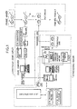
- Fig. 1 is a schematic diagram of a manufacturing method of a spectacle lens related to an aspect of the embodiment of the present invention
- Fig. 2 is a schematic diagram of an ordering screen
- Fig. 3 is a flowchart of a manufacturing process of a spectacle lens
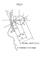
- Fig. 4 is a schematic diagram of an optical model of spectacles wearing.
- Reference Numeral 1 is a spectacles store (ordering party ), and Reference Numeral 2 is a spectacles processor (processing party).
- the spectacle lens manufacturing method of this aspect of the embodiment is such that a spectacle lens 3 is designed and manufactured based on information sent via a terminal apparatus installed at the spectacles store (ordering party) 1 to an information processing system installed at the processor (processing party) 2.
- the above-mentioned terminal apparatus via the above-mentioned terminal apparatus there is sent to the above-mentioned information processing system design and/or processing condition data information selected as needed from among information comprising a prescription value, which comprises spectacle lens information, spectacle frame information, and data related to the individual VR value of a spectacles wearer, layout information, and process specification information.
- the above-mentioned information processing system determines processing conditions by processing the information thereof, and obtains an optimized lens form based on an optical model of simulated wearing conditions, and a spectacle lens is manufactured.
- the preparation of prescription data and lens data for a spectacles wearer is performed at a spectacles store. Firstly, to determine a VR value for an individual (one of the prescription data), which is a characteristic of this aspect of the embodiment, a CR value of the right eye and left eye of each customer is measured, respectively, using a CR measuring apparatus.
- the axial length of the eye of the left and right eyes, respectively are measured using a popular commercial axial length measuring apparatus, and next, using a comparison coefficient of the relative location of the center of rotation of the eye (vertical direction) relative to the axial length of the eye, a CR value is computed via an operation, and this is used as the CR value for the left eye and right eye.
- the prescription is confirmed once again using either optometry data (spherical power, cylindrical power, cylinder axis, prismatic power, prism base setting, addition, distance PD, near PD, and so forth) from a customer's optometrist, or, as necessary, based on the optometry data thereof, using optometry equipment installed at a spectacles store.
- optometry data spherical power, cylindrical power, cylinder axis, prismatic power, prism base setting, addition, distance PD, near PD, and so forth
- lens data is prepared by making determinations based on interaction with the customer as to lens processing specification data, comprising the type of lens (single vision (spherical, aspherical), multifocal (bifocal, progressive) and so forth), power and type of lens material (glass, plastic), specification of surface processing options (tinting, wear-resistant coating (hard coating), antireflection coating, protection against ultraviolet rays, and so forth), center thickness, edge thickness, prism, and decentration, and layout specification data (for example, the inset, and specification for the location of the segment of a bifocal lens). Further, type of lens, and surface processing options can be substituted for by specifying a lens maker specification, and the model name thereof.
- lens processing specification data comprising the type of lens (single vision (spherical, aspherical), multifocal (bifocal, progressive) and so forth), power and type of lens material (glass, plastic), specification of surface processing options (tinting, wear-resistant coating (hard coating), antire
- Frames supplied by a frame maker are stocked at a spectacles store 1, and a customer selects a frame 4 of his/her liking.
- shape measurements are taken for the selected frame thereof using an installed 3-dimensional frame shape measuring apparatus (for example, GT-1000, 3DFT by Hoya Corporation), and frame data (for example, shape, FPD, bridge, frame curve, rim thickness, frame material, type (full frame, rimron, rimless), and so forth) is prepared.
- 3-dimensional frame shape measuring apparatus for example, GT-1000, 3DFT by Hoya Corporation
- frame data for example, shape, FPD, bridge, frame curve, rim thickness, frame material, type (full frame, rimron, rimless), and so forth
- the notation method for acquisition of frame data differs for each frame maker, and there are also various acquisition methods.
- the above-mentioned method indicated a method by which an actual frame shape is measured, but a method, in which information is already attached to a frame beforehand as a shape data barcode tag, acquires frame data by reading the data thereof. Further, in a case in which all frame data can be extracted from a frame model, frame data is extracted from the model data thereof.
- the frame tilt angle is determined, and the distance between the vertex of the cornea of the eye and the concave surface of a lens (VC value) is determined.
- a VR value is determined from the sum of this VC value and the CR value determined above.
- a spectacle lens ordering and inquiries system which is ordinarily utilized in the spectacles industry (for example, a typical system is the Hoya Online System manufactured by Hoya Corporation), can be used in the data communications thereof.
- a typical system is the Hoya Online System manufactured by Hoya Corporation
- this data communications is performed using a predetermined ordering screen.
- Fig. 2 is the system ordering screen thereof.
- Various information, comprising a VR value is sent to a host computer via the ordering screen.
- a host computer inputs and processes the various information sent from the above-mentioned terminal, and performs lens design simulation.
- Fig. 3 is a flowchart of a spectacle lens manufacturing process, and is a diagram showing a process, comprising simulation up until the manufacture of a prescription lens thereof.
- Fig. 3 first prescribed input items are checked.
- the main items thereof which are related to optical lens design, are physical lens data (refractive index, Abbe number, lspecific gravity, and so forth), prescription-related data (lens power, cylinder axis, addition, prismatic power, prism base setting , decentration, outer diameter, distance PD, near PD, lens thickness, VR value (CR value + VC value)), frame data (shape, DBL, FPD, frame curve, frame curve, and so forth), frame forward tilt, type of bevel, and other process specification data.
- lens data and frame data in particular, it is desirable to acquire basic physical and design data from a manufacturer beforehand.
- a spectacles wearing optical model for lens design is comprehensively simulated from the data thereof.
- Fig. 4 is a schematic diagram of an optical model of spectacles wearing, and is a diagram, which partially shows an outline of an optical model from the side.
- a lens is positioned in front of the eye by estimating the forward tilt of the frame.
- the VR value is the sum of the distance from the center of rotation R of the eye 1 to the vertex C of the cornea 11, that is, the CR value, and the distance from the vertex of the cornea C to a reference point V on the back surface 21 of a lens 2 (point of intersection of an extension of a straight line CR and a lens back surface 21) (VC value).
- optimization computations are performed by computer using lens design program calculations, the surface form of a concave surface, convex surface, and lens thickness are determined, and a prescription lens is determined.
- a prescription lens options based on variations of spectacle shape, such as an aspheric surface, spheric surface, bifocal, progressive , refractive index, and curvature, are taken into consideration, and either 1 type or a plurality of types of candidates are shown.
- a visual acuity examination apparatus uses a fixed VC value (hereinbelow, this value is referred to as VC0. Ordinarily, it is 14mm). Then, using this examination apparatus, an examiner (spectacles store, ophthalmologist, optician) obtains a corrective power value (D0). In the case of this embodiment, an examiner also takes into consideration frame shape, the shape of a patient's face, the corrective power value (D0) obtained via an optometry, and type of lens, and determines a VC value.
- the VC value is not the ordinarily used value of VC0 (14mm), and there are case which use as a prescription VC value a large measured VC value (for example, 20mm).
- D D0/(1 + (VC - VC0) ⁇ D0/1000)
- the corrective power thereof be corrected uniformly over the entire surface of a spectacle.
- D is less than 0.005.
- the ordering party uses an ordering system, which supplies (specifies) a VC value, CR value, D value (power) and so forth to the plant side, but if this embodiment is constituted such that in accordance with the ordering party transmitting initial information to the plant side, corrective computations are performed at the plant side, and design lens information is returned to the ordering party, and the ordering party references this information, prepares ordering information, and sends it to the plant side once again, the burden on the ordering party can be reduced.
- a lens curved surface form is initially selected as a candidate for use, and the optical characteristics of the lens thereof are determined using a ray tracing method or the like.
- a lens curved surface form the curved surface of which differs in accordance with a prescribed rule from the lens curved surface form thereof, is selected as a next candidate, and the optical characteristics of the lens thereof are determined in the same manner using a ray tracing method or the like.
- the optical characteristics of both lenses are evaluated by a prescribed method, and based on the results thereof, a determination is made to either use a candidate thereof, or to offer a subsequent candidate.
- design-related data comprising a VR
- design input data comprising a VR
- the spectacles optical model of Fig. 4 is assumed, and ray tracing computations are carried out.
- the starting point of ray tracing is the point of rotation (R).
- Points for carrying out ray tracing computations are set over the entire surface of a lens 2. The more numerous the number of set points, the more precise a design can be. For example, roughly 3 to 30,000 points can be used on a spectacle lens.
- the optical quantity (ordinarily, astigmatism, and curvature of field aberration) for each light ray is computed.
- the VC value and CR value which are related to the vertex of the cornea (C) are not used alone, but rather, the value of VR, which is the sum of the two, is used.
- an aspheric lens surface is expressed beforehand by an expression comprising a functionalized aspheric coefficient.
- a basic aspheric expression thereof is well known in the field of optical lenses, and furthermore, based thereon, as an application thereof, there are well-known expressions that determine functionalized optical surfaces on the basis of various lens design concepts.
- As specific aspheric expressions it is possible to cite, for example, Japanese Patent Application Laid-open No.S 52-115242, Japanese Patent Application Laid-open No. S58-24112, Japanese Patent Application Laid-open No. S61-501113, Japanese Patent Application Laid-open No. S64-40926, and WO97/26578. According to these patents, a lens surface can be determined by determining an aspheric coefficient in a disclosed expression.
- an optimization computation (method of least square attenuation), which changes an aspheric coefficient in a direction that reduces a sum of squares (called a merit function) weighted by the above-mentioned computed optical quantity that accompanies each light ray. Then, when a merit function constitutes less than a desired set optical quantity, an optimization computation is complete. An aspheric coefficient is determined at this point in time, and a lens form is decided. Furthermore, the above-mentioned optical quantities are clear even from the optical model of Fig.
- optical quantities are not individually functionally dependent on a VC value, and a CR value, which are 2 elements of a VR value, but rather have a functional relation to a VR value, which is the sum of a VC value and a CR value.
- Fig. 5 is a diagram showing optical data of a prescription lens with a VR value of 27mm, which was determined by the above-mentioned design technique.
- the basic specification for this prescription lens is a prescription for myopia, and is a single vision aspheric plastic lens (diethylene glycol bis allyl carbonate) of lens power: -4.00 diopter (D), refractive index (nd): 1.50, and outside diameter: 70mm.
- Fig. 6 is a diagram showing performance data of a case in which a person with a VR value of 27mm wore a prescription lens with a VR value of 27mm (Refer to Fig. 5). As shown in Fig. 6, there is practically no power error (average power error) in any angle of visual line, and it is evident that a lens design, which strives for optimization in an average power, has been performed, and that this lens design has extremely outstanding performance.
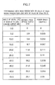
- Fig. 7 is a diagram showing performance data of a case in which a person with a VR value of 33mm wore a prescription lens with a VR value of 27mm (Refer to Fig. 5) (Target distance was set at infinity. Same holds true hereinbelow).
- large power errors average power errors
- power errors occur when a angle of visual line moves to a side field of view, which is away from the center of the lens, for example, in a direction of 30 degrees or 35 degrees.
- the quantity thereof is 0.245 (D) at 35 degrees, and, as can be seen, is extremely large.
- dioptric power classification is generally done at a pitch of 0.25 (D), and the power error value thereof is not a quantity that can be tolerated, indicating the need to select another prescription lens. Because all spectacle lenses ordinarily use the same design for a single lens item, the case shown in Fig. 7 can be thought of as a model case that occurs on a daily basis.
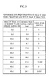
- Fig. 8 is a diagram showing optical data of a prescription lens with a VR value of 33mm.
- the difference in convex surface curve values is 0.0 diopter at a distance from the optical center of 0.0mm, and constitutes a -0.184 diopter at 15mm. Because this is an aspheric lens design, unlike a spheric lens design, a nonuniform convex curve correction is performed along the lens radial, and this differs from a uniform curve correction of power correction processing.
- Fig. 9 is a diagram showing performance data of a case in which a person with a VR value of 33mm wore a prescription lens with a VR value of 33mm (Refer to Fig. 8). As shown in Fig. 9, there is practically no power error (average power error) in any angle of visual line, and it is evident that a lens design, which strives for optimization in an average power, has been performed, and that this lens design has extremely outstanding performance.
- Fig. 10 is a diagram showing optical data of a prescription lens with a VR value of 27mm in a case in which the power is a prescription for hyperopia, and is +4.00 (D)
- Fig. 11 is a diagram showing performance data of a case in which a person with a VR value of 27mm wore a prescription lens with a VR value of 27mm (Refer to Fig. 10) (Target distance is set at infinity. The same holds true for hereinbelow)
- Fig. 12 is a diagram showing performance data of a case in which a person with a VR value of 33mm wore a prescription lens with a VR value of 27mm (Refer to Fig. 10)
- Fig. 10 is a diagram showing optical data of a prescription lens with a VR value of 27mm in a case in which the power is a prescription for hyperopia, and is +4.00 (D)
- Fig. 11 is a diagram showing performance data of a case in which a person with a VR value of 27
- FIG. 13 is a diagram showing optical data of a prescription lens with a VR value of 33mm in a case in which power is +4.00 (D)
- Fig. 14 is a diagram showing performance data of a case in which a person with a VR value of 33mm wore a prescription lens with a VR value of 33mm (Refer to Fig. 13). It is evident that the examples shown in these figures achieved the same results as the case shown in Fig. 5-Fig. 9.
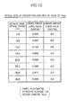
- Fig. 15 is a table for determining and showing power errors for various combinations of convex surface curve (base curve) values and lens power values in a case in which there is a single vision lens, and the VR value is set at 27mm
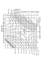
- Fig. 16 is a graph for showing the relationships indicated in Fig. 15 as power error contour lines.
- the examples shown in these figures are examples that treat the visual line direction as a 30 degree direction.
- the vertical axis is convex surface curves (base curves), and the horizontal axis is lens powers. From this table, it is clear that if a person with a lens power of -6.00 (D) selects a base curve of 2 (D), he will be able to achieve a lens with a good design that has a small power error.
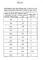
- Fig. 17 is a table for determining and showing power errors for various combinations of convex surface curve (base curve) values and lens power values in a case in which there is a single vision lens, and the VR value is set at 33mm
- Fig. 18 is a graph for showing the relationships indicated in Fig. 17 as power error contour lines.
- the examples shown in these figures are examples that treat the visual line direction as a 30 degree direction.
- the vertical axis is convex surface curves (base curves), and the horizontal axis is lens powers. From this table, it is clear that if a person with a lens power of -6.00 (D) selects a base curve of 1 (D), he will be able to achieve a lens with a good design that has a small power error.
- a case of a progressive-power lens will be explained.
- the design of a progressive-power lens is basically the same as that for a single vision lens, but from the standpoint of the structure thereof, there are also points that differ.
- the importance of a method for determining (correcting) the inset of a layout for a near portion will be explained while referring to Fig. 19 through Fig. 25.
- a progressive-power lens is constituted from a distance portion for long distance vision, a near portion for short distance vision, and an intermediate portion for intermediate vision, which smoothly connects the distance portion and the near portion.
- a spheric design is generally used for the distance portion and near portion (but there are also aspheric designs), and an aspheric design is used for the intermediate portion. Therefore, from the standpoint of design, it can be said that a progressive-power lens has a surface, which combines the spheric design of the above-mentioned single vision lens with an aspheric design.
- a progressive-power lens is a lens for presbyopia
- the portion from the intermediate portion to the near portion receives the most noticeable affects resulting from a difference in VR, and in this embodiment, the layout state thereof will be explained by focusing on the near portion thereof.
- the progressive-power lens of this embodiment is constituted such that lens is designed based on a prescribed optical design concept, the basic progressive refracting surface thereof is set as a functionalized surface via a prescribed numerical expression in a lens design program, and a prescription lens surface can be set up by inputting prescribed form determining element parameters, such as prescribed dioptric power.
- a prescription lens surface can be set up by inputting prescribed form determining element parameters, such as prescribed dioptric power.
- a lens surface is set up by determining the power distribution across an entire lens surface of a distance portion, a intermediate portion, and a near portion.
- elements for determining the power distribution thereof there are the base curve value of a distance portion, addition, horizontal power distribution of a distance portion and a near portion, the layout of a distance portion, near portion, and intermediate portion, progressive zone power change distribution, positioning of either a principal meridian or a principal sight line, positioning of astigmatism distribution, and positioning of average power distribution.
- a prescribed progressive refracting surface is set up by adding weighting to, and changing the weighting of these elements in accordance with individual design concepts.
- a progressive-power lens created based on a certain prescribed design concept like this a basic progressive refracting surface, comprising a plurality of base curves (for example, 2-8 curves) in accordance with the prescribed dioptric power thereof, is prepared beforehand. And a standard near portion inset INSETO is set as an initial value (for example, 2.5mm) in each.
- the near portion inset thereof is an inset toward the inner side of the near portion, which is set on a basic progressive refracting surface by treating as a reference a passage point on front surface of the lens of a line of sight at distance forward viewing (for example, a point on the principal meridian of a progressive-power lens), and is the distance in the horizontal direction from the principal meridian to the center of near portion of a progressive-power lens (Refer to Fig. 25).
- a basic progressive refracting surface of a prescribed base curve that corresponds to the prescribed dioptric power (for example, a 7 curve in the case of ADD 2.00 with a SPH + 3.00 diopter) is selected, and an initial value of INSET0 is set in the near portion of the basic progressive refracting surface thereof.
- this basic progressive refracting surface is treated as a front surface, and a lens design program is used to determine the form and location (a relative location on the optical axis relative to the front surface ) of a back surface of the lens, such that the lens thereof satisfies the power as prescribed (comprising a prism in a case in which a prism prescription is necessary).
- a back surface of the lens is set at this time, such that the thickness of the lens thereof is made thinnest owing to frame shape, type of frame, and layout of lens relative to frame.
- methods for determining a back surface of the lens having an optimal thickness like this are being implemented in the spectacles industry in lens ordering systems thereof, and are well-known technologies (for example, Japanese Patent Application Laid-open No. S59-55411, the HOYA METS system, and so forth), an explanation thereof will be omitted for this embodiment.
- a provisional optical model of a wearing state is set up on the basis of a prescribed near side object distance (working distance for near vision: a target distance for work to be done at a short distance) and the locations of the right and left eyes, a VR number of the invention of this case, which is obtained by measuring each individual spectacles wearer, distance PD, frame data, and frame forward tilt, and ray tracing computations are performed.
- the location of a point at which the visual line passes through the front surface of the lens when the right and left eyes actually identify a near object is determined via simulations based on the above-mentioned optical model, and next, a horizontal direction constituent (INSET1: the horizontal distance from the principal meridian to the center of near portion of the lens), which is the inset when there is convergence from the visual line in distance vision to the visual line in near vision in the location thereof, is determined.
- INSET1 the horizontal distance from the principal meridian to the center of near portion of the lens
- FIG. 24 is a diagram illustrating the divergence of the visual line between INSET0 and INSET1. This divergence is due to the fact that a line of sight passing through a lens on its way toward a near object is refracted by the lens, and the visual line actually passes through a location that differs from INSET0, which was set as a standard inset.
- the optical layout of the near portion changes in accordance with the changing of the inset, and to deal with this, the intermediate portion and distance portion are also changed, and a new progressive refracting surface is created while maintaining the basic refraction design surface, and then, an ideal inset is sought, and optimization is performed until optical conditions are satisfied such that the visual line in near vision is able to pass through a prescribed near object distance.
- INSET (n-1) INSET (n)
- the repetitive processing thereof (optimization) is completed, and a progressive refracting surface and back surface of the lens are determined as the final prescription lens.
- the refractive index of a lens material is 1.596
- the length of the progressive zone from the distance portion to the near portion is 15mm
- progressive refracting power increases having a location 4mm upwards from the center as a base point, and achieves addition 2.00 D at a location 11mm downward from the center.
- the PD of the right and left eye is 32.0mm in both the right and left
- the near object distance is set at 33.3cm.
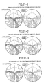
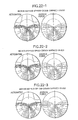
- Each diagram is a distribution of surface astigmatism, and surface average power for each progressive refracting surface, and shows a distribution range of ⁇ 80mm. Further, a ⁇ 50mm auxiliary circle is placed on the inside portion.
- Fig. 20-1 is a progressive refracting surface form for which the distance power (DF) for both the right and left is set at +3.00D, the convex curve (ABC) is set at 5.94D, lens thickness at the geometric center is set at 5.1mm, and the prism at the geometric center is set at 1.0 ⁇ base 270°
- Fig. 20-2 is a progressive refracting surface form for which the distance power (DF) for both the right and left is set at 0.00D, the convex curve (ABC) is set at 4.72D, center thickness is set at 2.7mm, and the prism is set at 1.0 ⁇ base 270°
- Fig. 20-1 is a progressive refracting surface form for which the distance power (DF) for both the right and left is set at +3.00D, the convex curve (ABC) is set at 5.94D, lens thickness at the geometric center is set at 5.1mm, and the prism at the geometric center is set at 1.0 ⁇ base 270°
- Fig. 20-2
- 20-3 is a progressive refracting surface form for which the distance power (DF) for both the right and left is set at -3.00D, the convex curve (ABC) is set at 3.49D, center thickness is set at 1.5mm, and the prism is set at 1.0 ⁇ base 270°.
- Fig. 21-1 is a progressive refracting surface form for which the distance power (DF) for both the right and left is set at +3.00D, the convex curve (ABC) is set at 5.94D, center thickness is set at 5.1mm, and the prism is set at 1.0 ⁇ base 270°
- Fig. 21-2 is a progressive refracting surface form for which the distance power (DF) for both the right and left is set at 0.00D, the convex curve (ABC) is set at 4.72D, center thickness is set at 2.7mm, and the prism is set at 1.0 ⁇ base 270°
- Fig. 21-1 is a progressive refracting surface form for which the distance power (DF) for both the right and left is set at +3.00D, the convex curve (ABC) is set at 5.94D, center thickness is set at 5.1mm, and the prism is set at 1.0 ⁇ base 270°
- Fig. 21-2 is a progressive refracting surface form for which the distance power (
- 21-3 is a progressive refracting surface form for which the distance power (DF) for both the right and left is set at -3.00D, the convex curve (ABC) is set at 3.49D, center thickness is set at 1.5mm, and the prism is set at 1.0 ⁇ base 270°.
- Fig. 22-1 is a progressive refracting surface form for which the distance power (DF) for both the right and left is set at +3.00D, the convex curve (ABC) is set at 5.94D, center thickness is set at 5.1mm, and the prism is set at 1.0 ⁇ base 270°
- Fig. 22-2 is a progressive refracting surface form for which the distance power (DF) for both the right and left is set at 0.00D, the convex curve (ABC) is set at 4.72D, center thickness is set at 2.7mm, and the prism is set at 1.0 ⁇ base 270°
- Fig. 22-1 is a progressive refracting surface form for which the distance power (DF) for both the right and left is set at +3.00D, the convex curve (ABC) is set at 5.94D, center thickness is set at 5.1mm, and the prism is set at 1.0 ⁇ base 270°
- Fig. 22-2 is a progressive refracting surface form for which the distance power (
- 22-3 is a progressive refracting surface form for which the distance power (DF) for both the right and left is set at -3.00D, the convex curve (ABC) is set at 3.49D, center thickness is set at 1.5mm, and the prism is set at 1.0 ⁇ base 270°.
- Fig. 23 shows the results of calculating as specific numerals the near portion insets INSET provided to the respective determined progressive refracting surfaces shown in Fig. 20, Fig. 21, and Fig. 22. From this it is clear that the insets of the near portions change in accordance with differences in VR.
- this method can also be used in the same way in a case in which the optical layout of the near portion of a bifocal (segment height, left-right location, and so forth) is determined, and a prescription lens is determined. That is, as shown in Fig. 26, since the near segment portion of a bifocal layout block is partitioned by a boundary line, the location of the near portion is adjusted in the same manner as the above-mentioned example of a progressive-power lens.
- astigmatism, average power error, and distortion can also be determined from ray tracing for either a selected basic progressive refracting surface, or a corrected progressive refracting surface and a back surface of the lens in the flowchart of Fig. 19.
- the form of a progressive refracting surface can be corrected, and aberration correction can be performed simultaneously from such values as astigmatism, average power error, and distortion determined by ray tracing.
- optimization is performed beforehand for a basic progressive refracting surface so as to diminish the respective deviations ( ⁇ A1, ⁇ B1, ⁇ C1) between estimated astigmatism A0, average power distribution B0 and distortion C0, and astigmatism A1, average power distribution B1 and distortion C1 determined by ray tracing.
- Weighting which corresponds to a location on a basic progressive refracting surface (center area, lateral area, distance portion, near portion, and so forth), is performed for each of the deviations thereof at this time.
- ray tracing is performed, and optimization is performed in the respective areas by using in the distance portion a VR value that differs at distance vision and at near vision.
- two VR values are interpolated and used at distance vision and near vision in accordance with a localized additional refracting power in the location thereof.
- a partial VR value for either only a distance portion, or only a near portion.
- the results thereof are displayed using, for example, an astigmatism diagram, bird's-eye view, and so forth, by a display processing program for optical performance computation results provided in a lens design program, and are constituted so as to enable comparison and study. Further, such results are set up to also be displayable on the personal computer of the ordering party via a communications line.
- the spectacles store side either confirms or selects a desired lens based on such results. Naturally, wearing parameters can be changed, new wearing conditions can be set, and a new prescription lens can be determined based on the simulation data thereof.
- results thereof there is performed, based on information of each type sent to a host computer by a display processing program for optical performance computation results provided in a lens design program, computations to determine how a spectacle lens of the individual design that is being ordered differs from a standard spectacle lens, the results thereof are returned to a spectacle store side terminal apparatus, and the differences therebetween can also be displayed thereon.
- a standard lens to be used as a comparison object can also be specified by the spectacles store side at this time, and in a case in which there is no specification of a standard lens as a comparison object, this embodiment is constituted such that a lens set in the host computer beforehand is treated as the comparison object. Based on such results, the spectacles store side can check the differences between a desired individual designed lens and a standard lens.
- a number of methods can be cited for comparing the differences between a spectacle lens of an individual design, and a standard spectacle lens.
- One method is a method in which the kind of aberration distribution achieved when the end user puts on the spectacles thereof is determined by ray tracing, and the results thereof are displayed on the spectacles store side terminal apparatus by lining up the aberration distribution of the standard spectacles beside the aberration distribution of the individually designed spectacles.
- a method such as the following.
- a method which, in the case of a single-vision aspheric lens, compares and displays using numerals and graphs a power error and astigmatism of when there is a 30 degree angle of visual line toward the lens concave surface, and the lens convex surface curve at the design center location of a spectacle lens of an individual design, and a standard spectacle lens, respectively.
- processing data thereof is prepared.
- This processing data is prepared on the basis of a lens processing program. Processing conditions of processing equipment are determined, driving of processing equipment is controlled, and instructions are given for selecting processing tools and for selecting a lens material by processing data. This processing data are sent to each manufacturing equipment in a factory with processing instructions.
- a lens blank is selected based on the processing instructions, and cutting and grinding lens processing are performed using an NC cutting machine. Also in a case in which surface processing (formation of a wear-resistant hard coating, formation of an anti-reflection coating, lens tinting, water repellant processing, formation of an ultraviolet ray cutting coating, anti-fogging treatment, and so forth) is required, processing is performed here. Then, a round shaped prescription lens is completed. Further, at this point, there are also cases in which a lens can be selected from finished products stocked beforehand for lens manufacture.
- the above-mentioned round lens is made to correspond to a prescribed lens form, and a bevel (V-shaped edge) is formed at the edge based on spectacles layout information.
- the formation of the bevel is performed by a machining center. This processing is performed using a tool and processing method disclosed in Japanese Utility Model Application Laid-open No. H6-17853, and Japanese Patent Application Laid-open No. H6-34923, which are related to the above application of this applicant.
- selecting of type of lens material glass, plastic, polycarbonate, acrylic, and so forth
- selecting of frame material inputting of frame PD (FPD, DBL), inputting of PD (both eyes, one eye), inputting of horizontal decentration distance X, inputting of vertical decentration distance Y, inputting of astigmatism axis, inputting of finished size, and specifications of bevel shape are used as processing conditions, and when the processing equipment is set to the processing mode, the input data thereof is automatically introduced by a program.
- a bevel formed lens is manufactured in this manner, passes through an inspection process at the factory, and is shipped to a spectacles store. At the spectacles store, the bevel formed lens is fitted into a selected frame, and spectacles are assembled. Further, in this embodiment, the bevel formation was explained as an aspect, which is implemented by a manufacturer, but this can also be performed at a spectacles store, and is not particularly limited to the manufacturing flow of this embodiment.
- a lens optical performance evaluation index average power was utilized in the above-mentioned aspect of the embodiment, but it is not limited thereto.
- indices such as astigmatism, average power error, distortion, spectacles magnification, RMS, and combinations thereof, and the index is not particularly limited.
- a lens design program, inquiry-based simulation program, display program and so forth can be incorporated beforehand into an ordering party terminal and accessory equipment (CD or the like), and can also be run on the same personal computer in the sense of an apparatus having a kind of information processing function.
- the present invention makes it possible to design and manufacture a higher performance spectacle lens that accords with the VR value (VC +CR) of each individual person by determining, by measuring each individual spectacles wearer, a value for the distance VR from a reference point on the back surface of a spectacle lens to the center of rotation of the eye, which adds a value for the distance VC from a reference point on the back surface of a spectacle lens when spectacles are being worn to the vertex of the cornea of a spectacles wearer's eyeball, which is one of the required data in spectacle lens design, and a value for the distance CR from the above-mentioned cornea vertex to the center of rotation of the eye, using the value thereof to perform spectacle lens design, and to manufacture a spectacle lens on the basis of the design specifications thereof.
- this spectacle lens and manufacturing method therefor makes it possible to supply a spectacle lens that excels in feeling when wearing it by designing and manufacturing a spectacle lens taking into consideration the distance between the center of rotation of the eye and the spectacle lens for an individual spectacles wearer, and can be applied to any of a single vision lens, a multifocal lens, and a progressive-power lens.
Landscapes
- Physics & Mathematics (AREA)
- Health & Medical Sciences (AREA)
- Ophthalmology & Optometry (AREA)
- General Physics & Mathematics (AREA)
- Optics & Photonics (AREA)
- General Health & Medical Sciences (AREA)
- Mathematical Physics (AREA)
- Eyeglasses (AREA)
- Crystals, And After-Treatments Of Crystals (AREA)
- Preparation Of Compounds By Using Micro-Organisms (AREA)
Priority Applications (1)
| Application Number | Priority Date | Filing Date | Title |
|---|---|---|---|
| EP07102210.7A EP1793262B1 (fr) | 1999-02-12 | 2000-02-10 | Verre de lunettes et son procédé de fabrication |
Applications Claiming Priority (3)
| Application Number | Priority Date | Filing Date | Title |
|---|---|---|---|
| JP3501799 | 1999-02-12 | ||
| JP3501799 | 1999-02-12 | ||
| PCT/JP2000/000763 WO2000048035A1 (fr) | 1999-02-12 | 2000-02-10 | Lunettes et leur procede de fabrication |
Related Child Applications (1)
| Application Number | Title | Priority Date | Filing Date |
|---|---|---|---|
| EP07102210.7A Division EP1793262B1 (fr) | 1999-02-12 | 2000-02-10 | Verre de lunettes et son procédé de fabrication |
Publications (3)
| Publication Number | Publication Date |
|---|---|
| EP1154302A1 true EP1154302A1 (fr) | 2001-11-14 |
| EP1154302A4 EP1154302A4 (fr) | 2002-07-03 |
| EP1154302B1 EP1154302B1 (fr) | 2009-08-05 |
Family
ID=12430313
Family Applications (2)
| Application Number | Title | Priority Date | Filing Date |
|---|---|---|---|
| EP07102210.7A Expired - Lifetime EP1793262B1 (fr) | 1999-02-12 | 2000-02-10 | Verre de lunettes et son procédé de fabrication |
| EP00902921A Expired - Lifetime EP1154302B1 (fr) | 1999-02-12 | 2000-02-10 | Lunettes et leur procede de fabrication |
Family Applications Before (1)
| Application Number | Title | Priority Date | Filing Date |
|---|---|---|---|
| EP07102210.7A Expired - Lifetime EP1793262B1 (fr) | 1999-02-12 | 2000-02-10 | Verre de lunettes et son procédé de fabrication |
Country Status (11)
| Country | Link |
|---|---|
| US (2) | US6637880B1 (fr) |
| EP (2) | EP1793262B1 (fr) |
| JP (3) | JP5031083B2 (fr) |
| KR (1) | KR100608406B1 (fr) |
| CN (1) | CN1189775C (fr) |
| AT (1) | ATE438880T1 (fr) |
| AU (1) | AU769864B2 (fr) |
| CA (1) | CA2362129C (fr) |
| DE (1) | DE60042681D1 (fr) |
| HK (1) | HK1043840B (fr) |
| WO (1) | WO2000048035A1 (fr) |
Cited By (22)
| Publication number | Priority date | Publication date | Assignee | Title |
|---|---|---|---|---|
| DE10121133A1 (de) * | 2001-04-30 | 2002-12-19 | Rodenstock Optik G | Verfahren zur Herstellung eines Brillenglases unter Berücksichtigung der optimalen, individuellen Progressionslänge |
| WO2004034131A1 (fr) * | 2002-10-08 | 2004-04-22 | Hoya Corporation | Procede permettant de determiner la valeur optique de verres de lunettes, procede de production de verres de lunettes, verres de lunettes et systeme de commande et de reception de commande |
| EP1336891A4 (fr) * | 2000-10-27 | 2005-10-12 | Hoya Corp | Procede de production de verres de lunettes et systeme d'apport de verres de lunettes |
| WO2006061832A2 (fr) * | 2004-12-06 | 2006-06-15 | Opti-Clip International Llc | Imagerie d'une premiere paire de verres optiques permettant la fabrication a distance d'une seconde paire de verres optiques |
| US7219075B2 (en) | 2002-04-16 | 2007-05-15 | Nidek Co., Ltd. | Lens ordering method and lens ordering system |
| EP1837699A1 (fr) * | 2006-03-24 | 2007-09-26 | ESSILOR INTERNATIONAL Compagnie Générale d'Optique | Procédé de détermination d'une lentille ophtalmique progressive |
| FR2910647A1 (fr) * | 2007-05-29 | 2008-06-27 | Essilor Int | Procede de detourage de lentilles ophtalmiques par lecture et mise a jour d'un registre de base de donnees de lentilles et/ou de montures |
| WO2008089997A1 (fr) * | 2007-01-25 | 2008-07-31 | Rodenstock Gmbh | Points de référence pour orthoposition |
| WO2010097161A1 (fr) * | 2009-02-26 | 2010-09-02 | Carl Zeiss Vision Gmbh | Procédé et dispositif pour déterminer la position du point de rotation de l'œil |
| WO2010133813A1 (fr) | 2009-05-20 | 2010-11-25 | Essilor International (Compagnie Generale D'optique) | Lentille ophtalmique de type unifocale |
| US8322855B2 (en) | 2004-05-06 | 2012-12-04 | Indo Internacional S.A. | Method for determining the visual behaviour of a Person |
| EP2667241A1 (fr) * | 2012-05-23 | 2013-11-27 | Carl Zeiss Vision International GmbH | Procédé de fabrication d'un verre de lunettes fournissant une correction astigmate et lunettes comprenant un tel verre de lunettes |
| EP2733648A1 (fr) * | 2008-08-04 | 2014-05-21 | Carl Zeiss Vision GmbH | Systèmes et procédés de commande de lentilles |
| EP3109693A4 (fr) * | 2014-02-20 | 2017-10-11 | Nikon Corporation | Procédé de conception de verres de lunettes, procédé de production de verres de lunettes , verres de lunettes, système de conception de verres de lunettes, programme de conception de verres de lunettes, et support d'enregistrement |
| EP3261003A1 (fr) * | 2012-10-18 | 2017-12-27 | Essilor International | Procédé de fourniture d'au moins une partie d'un équipement de lunettes |
| EP1744203B1 (fr) * | 2004-05-05 | 2018-04-11 | Horizons Optical S.L.U. | Procede de calcul d'une lentille ophtalmique et lentille correspondante |
| EP3309603A1 (fr) * | 2016-10-11 | 2018-04-18 | Essilor International | Procédé de détermination d'un paramètre d'un équipement optique |
| EP3395233A1 (fr) * | 2017-04-25 | 2018-10-31 | Johnson & Johnson Vision Care Inc. | Procédés et système de suivi de traitement de l'amétropie |
| KR20180119505A (ko) * | 2017-04-25 | 2018-11-02 | 존슨 앤드 존슨 비젼 케어, 인코포레이티드 | 비정시 치료 추적 방법 및 시스템 |
| US10642067B2 (en) | 2016-01-27 | 2020-05-05 | Johnson & Johnson Vision Care, Inc. | Ametropia treatment tracking methods and system |
| DE10236713B4 (de) * | 2002-08-07 | 2020-08-06 | Carl Zeiss | Verfahren und Vorrichtung zum Herstellen von Brillengläsern aus Kunststoff |
| EP3722865A1 (fr) * | 2019-04-11 | 2020-10-14 | Essilor International | Procédés et systèmes pour optimiser une fonction optique d'une lentille ophtalmique progressive dans des conditions de port spécifiques |
Families Citing this family (84)
| Publication number | Priority date | Publication date | Assignee | Title |
|---|---|---|---|---|
| CA2362129C (fr) * | 1999-02-12 | 2006-10-03 | Hoya Corporation | Lunettes et leur procede de fabrication |
| JP2002068610A (ja) * | 2000-08-25 | 2002-03-08 | Mitsubishi Electric Corp | 昇降機設備計画の情報提供手法 |
| JP4707706B2 (ja) * | 2000-10-27 | 2011-06-22 | Hoya株式会社 | 眼鏡レンズ供給方法 |
| JP4707705B2 (ja) * | 2000-10-27 | 2011-06-22 | Hoya株式会社 | 眼鏡レンズ供給方法 |
| DE10103113A1 (de) * | 2001-01-24 | 2002-08-01 | Rodenstock Optik G | Verfahren zur Herstellung eines Brillenglases |
| US7025910B2 (en) * | 2001-02-20 | 2006-04-11 | Q2100, Inc | Method of entering prescription information |
| US6962669B2 (en) * | 2001-02-20 | 2005-11-08 | Q2100, Inc. | Computerized controller for an eyeglass lens curing apparatus |
| US7074352B2 (en) * | 2001-02-20 | 2006-07-11 | Q2100, Inc. | Graphical interface for monitoring usage of components of a lens forming apparatus |
| US7037449B2 (en) * | 2001-02-20 | 2006-05-02 | Q2100, Inc. | Method for automatically shutting down a lens forming apparatus |
| US7060208B2 (en) * | 2001-02-20 | 2006-06-13 | Q2100, Inc. | Method of preparing an eyeglass lens with a controller |
| US7051290B2 (en) * | 2001-02-20 | 2006-05-23 | Q2100, Inc. | Graphical interface for receiving eyeglass prescription information |
| US7045081B2 (en) * | 2001-02-20 | 2006-05-16 | Q2100, Inc. | Method of monitoring components of a lens forming apparatus |
| JP2002350785A (ja) * | 2001-05-28 | 2002-12-04 | Menicon Co Ltd | 眼用レンズの設計方法 |
| DE10140656A1 (de) * | 2001-08-24 | 2003-03-13 | Rodenstock Optik G | Verfahren zum Entwerfen und Optimieren eines individuellen Brillenglases |
| US7158222B2 (en) * | 2002-05-16 | 2007-01-02 | Hoya Corporation | Method and device for evaluating spectacle lens or mold for molding spectacle lens, and method and system for manufacturing spectacle lens |
| US20040004633A1 (en) * | 2002-07-03 | 2004-01-08 | Perry James N. | Web-based system and method for ordering and fitting prescription lens eyewear |
| JP4158906B2 (ja) * | 2002-07-19 | 2008-10-01 | Hoya株式会社 | 眼鏡レンズの光学性能表示方法 |
| US7083279B2 (en) * | 2002-08-07 | 2006-08-01 | Carl Zeiss Vision Gmbh | Process and an apparatus for making plastic material spectacle lenses |
| US7154111B2 (en) * | 2002-10-16 | 2006-12-26 | Campbell Science Group, Inc. | Cornea characteristics measuring device |
| DE10313275A1 (de) * | 2003-03-24 | 2004-10-14 | Rodenstock Gmbh | Verfahren zum Berechnen eines individuellen Progressivglases |
| DE10338033A1 (de) * | 2003-08-19 | 2005-03-31 | Rodenstock Gmbh | Individuelles Einstärkenbrillenglas |
| DE10339948A1 (de) * | 2003-08-29 | 2005-04-28 | Rodenstock Gmbh | Fehlertolerantes Progressivglasdesign |
| US8241534B2 (en) * | 2004-03-09 | 2012-08-14 | Hoya Corporation | Spectacle lens manufacturing method and spectacle lens manufacturing system |
| JP2005313548A (ja) * | 2004-04-30 | 2005-11-10 | Hoya Corp | 眼鏡レンズへのマーキング方法及びシステム、並びに眼鏡レンズ |
| US7677726B2 (en) | 2004-06-29 | 2010-03-16 | Hoya Corporation | Manufacturing method for spectacle lens and spectacle lens |
| AU2004325004B2 (en) * | 2004-11-16 | 2012-03-22 | Essilor International | Method for designing spectacle lenses taking into account an individual's head and eye movement |
| DE102004059448A1 (de) * | 2004-11-19 | 2006-06-01 | Rodenstock Gmbh | Verfahren und Vorrichtung zum Fertigen eines Brillenglases; System und Computerprogrammprodukt zum Fertigen eines Brillenglases |
| FR2878975B1 (fr) * | 2004-12-03 | 2007-02-16 | Essilor Int | Procede et dispositif de preparation au montage d'un job de deux lentilles ophtalmiques d'une meme paire de lunettes |
| EP1752815A1 (fr) * | 2005-08-11 | 2007-02-14 | Essilor International (Compagnie Generale D'optique) | Méthode de fabrication d'un système optique |
| DE102005038859A1 (de) * | 2005-08-17 | 2007-03-01 | Rodenstock Gmbh | Tool zur Berechnung der Performance von Gleitsichtgläsern |
| FR2906621B1 (fr) * | 2006-09-28 | 2008-11-28 | Essilor Int | Procede de determination d'une lentille ophtalmique |
| WO2008089999A1 (fr) * | 2007-01-25 | 2008-07-31 | Rodenstock Gmbh | Procédé d'optimisation d'un verre de lunettes |
| US7784937B2 (en) | 2007-06-05 | 2010-08-31 | Digital Vision, Inc. | System and method of surfacing a lens, such as a lens for use with eyeglasses |
| US8002406B2 (en) | 2007-10-30 | 2011-08-23 | Digital Vision, Inc. | System and method for manufacturing a lens, such as an ophthalmic lens |
| EP2028531B1 (fr) * | 2007-12-28 | 2016-05-04 | Essilor International (Compagnie Generale D'optique) | Procédé de sélection d'une lentille ophtalmique semi-finie selon un cadre de lunettes donné |
| ES2401456T3 (es) * | 2007-12-28 | 2013-04-19 | Essilor International (Compagnie Generale D'optique) | Método para seleccionar curvas de base para una lente oftálmica y método de fabricación de lentes de gafas relacionadas |
| EP2028529B1 (fr) * | 2007-12-28 | 2020-09-09 | Essilor International | Procédé de calcul d'un système optique selon une monture de lunettes donné |
| EP2027968B1 (fr) * | 2007-12-28 | 2010-11-03 | Essilor International (Compagnie Generale D'optique) | Procédé de détermination de paramètres de monturisation d'une lentille ophtalmique |
| EP2031434B1 (fr) * | 2007-12-28 | 2022-10-19 | Essilor International | Procédé synchrone pour obtenir des fonctions de lunettes à commander |
| EP2037314B1 (fr) * | 2007-12-28 | 2021-12-01 | Essilor International | Procédé et supports informatiques pour choisir des verres de lunettes adaptés à un cadre |
| US8690323B2 (en) * | 2008-04-28 | 2014-04-08 | Hoya Corporation | Method of selecting lens design standard |
| US8333469B2 (en) * | 2008-04-30 | 2012-12-18 | Essilor International (Compagnie Generale D'optique) | Method and system for providing financial data for optical labs sharing lens calculation software |
| JP5599798B2 (ja) * | 2008-09-04 | 2014-10-01 | エシロール アンテルナシオナル (コンパニー ジェネラル ドプティック) | 仕上げパラメータを提供するための方法 |
| EP2342599B1 (fr) * | 2008-09-24 | 2016-09-07 | Essilor International (Compagnie Générale D'Optique) | Procédé pour déterminer l'inclinaison dans une lentille de lunettes progressive |
| WO2010035726A1 (fr) * | 2008-09-24 | 2010-04-01 | 東海光学 株式会社 | Procédé de conception de lentille oculaire |
| JP4888466B2 (ja) * | 2008-10-17 | 2012-02-29 | セイコーエプソン株式会社 | 内面累進多焦点レンズの製造方法 |
| ES2401123T3 (es) | 2009-01-23 | 2013-04-17 | Rodenstock Gmbh | Control de diseño por medio de un polígono de diseño |
| WO2010119183A1 (fr) * | 2009-04-17 | 2010-10-21 | Essilor International (Compagnie Générale d'Optique) | Procédé de détermination d'une lentille ophtalmique |
| US8340799B2 (en) | 2009-12-22 | 2012-12-25 | Digital Vision, Inc. | Automated optical lens processing system, such as a system for providing supplemental information to laboratory technicians |
| JP5687435B2 (ja) * | 2010-04-16 | 2015-03-18 | ホーヤ レンズ マニュファクチャリング フィリピン インク | 眼鏡レンズ選択システム、眼鏡レンズ選択方法、眼鏡レンズ選択装置及び眼鏡レンズ選択結果提示装置 |
| DE102010018549B4 (de) | 2010-04-28 | 2022-08-18 | Rodenstock Gmbh | Computerimplementiertes Verfahren zur Berechnung eines Brillenglases unter der Berücksichtigung der Augenrotation, Vorrichtung zum Berechnen oder Optimieren eines Brillenglases, Computerprogrammerzeugnis, Speichermedium, Verfahren zum Herstellen eines Brillenglases, Vorrichtung zum Herstellen eines Brillenglases sowie Verwendung eines Brillenglases |
| CN103237627B (zh) * | 2010-10-04 | 2016-11-09 | 施耐德两合公司 | 用于加工光学透镜的设备和方法以及光学透镜和用于光学透镜的输送容器 |
| JP5784418B2 (ja) * | 2011-08-30 | 2015-09-24 | Hoya株式会社 | 眼鏡レンズの設計方法、眼鏡レンズの製造方法、及び眼鏡レンズの設計システム |
| US20130132898A1 (en) * | 2011-11-17 | 2013-05-23 | Michael F. Cuento | System, Method and Software Product in Eyewear Marketing, Fitting Out and Retailing |
| US9236024B2 (en) | 2011-12-06 | 2016-01-12 | Glasses.Com Inc. | Systems and methods for obtaining a pupillary distance measurement using a mobile computing device |
| BR112014013687B1 (pt) * | 2011-12-08 | 2021-12-21 | Hoya Corporation | Sistema de corte de lente, e, método para fabricar uma lente de óculos |
| EP2629140B1 (fr) * | 2012-02-16 | 2019-08-14 | Hoya Corporation | Système, appareil et méthode de simulation permettant à un porteur de lunettes de voir l'effet de celles-ci sur son visage |
| EP2645193B1 (fr) | 2012-03-30 | 2019-04-24 | Johnson & Johnson Vision Care, Inc. | Commande de forme de contour |
| US9483853B2 (en) | 2012-05-23 | 2016-11-01 | Glasses.Com Inc. | Systems and methods to display rendered images |
| US20130314401A1 (en) | 2012-05-23 | 2013-11-28 | 1-800 Contacts, Inc. | Systems and methods for generating a 3-d model of a user for a virtual try-on product |
| US9286715B2 (en) | 2012-05-23 | 2016-03-15 | Glasses.Com Inc. | Systems and methods for adjusting a virtual try-on |
| JP6169343B2 (ja) * | 2012-10-25 | 2017-07-26 | 株式会社ニコン・エシロール | 眼鏡レンズ設計方法および眼鏡レンズ製造方法 |
| JP6169342B2 (ja) * | 2012-10-25 | 2017-07-26 | 株式会社ニコン・エシロール | 眼鏡レンズ発注装置、眼鏡レンズ提供システム、眼鏡レンズ発注プログラム、眼鏡レンズ受注装置および眼鏡レンズ受注プログラム |
| EP2916164B1 (fr) * | 2012-11-05 | 2021-06-02 | Nikon Corporation | Procédé de conception de verre de lunettes et système de conception de verre de lunettes |
| US9676765B2 (en) | 2012-11-07 | 2017-06-13 | Karus Therapeutics Limited | Histone deacetylase inhibitors and their use in therapy |
| CN105008987B (zh) * | 2013-02-28 | 2017-06-20 | Hoya株式会社 | 眼镜镜片的设计系统、供给系统、设计方法及制造方法 |
| US10216004B2 (en) | 2013-04-29 | 2019-02-26 | Essilor International | System for providing an opthalmic lens |
| WO2014181137A1 (fr) | 2013-05-10 | 2014-11-13 | Karus Therapeutics Ltd | Nouveaux inhibiteurs de l'histone désacétylase |
| CN103487947B (zh) * | 2013-09-30 | 2015-02-18 | 苏州大学 | 一种高曲率大口径自由曲面镜片的检测方法及其设计加工方法 |
| JP6312538B2 (ja) * | 2014-06-18 | 2018-04-18 | 株式会社ニコン・エシロール | レンズ設計方法、レンズ製造方法、レンズ設計プログラム、及びレンズ設計システム |
| JP6460728B2 (ja) * | 2014-10-31 | 2019-01-30 | 株式会社ニコン・エシロール | レンズ設計方法、レンズ製造方法、レンズ設計プログラム、及びレンズ設計システム |
| EP3037869A1 (fr) * | 2014-12-23 | 2016-06-29 | Essilor International (Compagnie Generale D'optique) | Procédé permettant de comparer une première lentille ophtalmique avec une seconde lentille ophtalmique |
| BR122020016722B1 (pt) * | 2015-04-15 | 2023-04-11 | Vision Ease, Lp | Lente oftálmica |
| CN108885355A (zh) | 2016-03-04 | 2018-11-23 | 依视路国际公司 | 确定表征眼科镜片的屈光力值的方法和相应电子装置 |
| EP3424009A1 (fr) | 2016-03-04 | 2019-01-09 | Essilor International | Procédé de commande d'une lentille ophtalmique et système correspondant |
| KR102280371B1 (ko) | 2016-11-30 | 2021-07-21 | 가부시키가이샤 니콘. 에시로루 | 안경 렌즈의 설계 방법, 안경 렌즈의 제조 방법, 안경 렌즈 발주 장치, 안경 렌즈 수주 장치, 안경 렌즈 수발주 시스템, 누진 굴절력 렌즈, 단초점 렌즈 |
| US10001660B1 (en) * | 2017-02-24 | 2018-06-19 | Edward Chow | Methods of designing reverse geometry lenses for myopia control |
| EP3398501A1 (fr) * | 2017-05-02 | 2018-11-07 | Essilor International | Procédé de détermination de l'astigmatisme d'un il d'une personne |
| CN112748587B (zh) | 2017-07-03 | 2022-10-28 | 株式会社尼康依视路 | 眼镜镜片的设计方法、眼镜镜片的制造方法及眼镜镜片 |
| DE102018002384C5 (de) * | 2018-03-22 | 2022-03-10 | Shape Engineering GmbH | Verfahren zur Herstellung eines Brillenglases |
| EP3844562A1 (fr) | 2018-08-28 | 2021-07-07 | Essilor International | Procédé pour déterminer une lentille ophtalmique |
| DE102018124608A1 (de) * | 2018-10-05 | 2020-04-09 | Arburg Gmbh + Co Kg | Formschließeinheit für eine Spritzgießmaschine sowie Verfahren zum Verriegeln eines Kraftübertragungselements |
| JP7393169B2 (ja) * | 2019-09-27 | 2023-12-06 | ホヤ レンズ タイランド リミテッド | 眼鏡レンズ設計システム、眼鏡レンズ設計方法、及び眼鏡レンズ設計プログラム |
| CN111552096A (zh) * | 2020-04-29 | 2020-08-18 | 陈奎 | 儿童多同心环渐近能部分恢复视力的眼镜片 |
Citations (7)
| Publication number | Priority date | Publication date | Assignee | Title |
|---|---|---|---|---|
| US3434781A (en) * | 1965-03-15 | 1969-03-25 | American Optical Corp | Ophthalmic lens series |
| US3960442A (en) * | 1974-08-05 | 1976-06-01 | American Optical Corporation | Ophthalmic lens series |
| US4310225A (en) * | 1979-08-06 | 1982-01-12 | Gentex Corporation | Ophthalmic lens series |
| EP0576268A1 (fr) * | 1992-06-24 | 1993-12-29 | Hoya Corporation | Production de verres de lunettes |
| EP0710526A1 (fr) * | 1994-10-31 | 1996-05-08 | Nikon Corporation | Verre de lunettes et son procédé de fabrication |
| DE19612284A1 (de) * | 1996-03-28 | 1997-10-02 | Zeiss Carl Fa | Multifokale Brillenlinse |
| EP0857993A2 (fr) * | 1997-01-16 | 1998-08-12 | Carl Zeiss | Verre de lunettes à face frontale sphérique et à face postérieure multifocale, et méthode pour sa fabrication |
Family Cites Families (17)
| Publication number | Priority date | Publication date | Assignee | Title |
|---|---|---|---|---|
| CA1077315A (fr) | 1976-03-22 | 1980-05-13 | Donald B. Whitney | Lentille ophtalmique et methode pour correction d'astigmatisme |
| JPS5824112A (ja) | 1981-07-08 | 1983-02-14 | オプテイツシエ・ウエルケ・ゲ−・ロ−デンストツク | 正の屈折値の大きい眼鏡用レンズ |
| JPS5955411A (ja) | 1982-09-24 | 1984-03-30 | Hoya Corp | 眼鏡レンズの最適肉厚決定方法 |
| DE3343891C2 (de) | 1983-12-05 | 1986-06-05 | Optische Werke G. Rodenstock, 8000 München | Mehrstärkenglas mit hohem positiven Brechwert |
| JPS6440926A (en) | 1987-08-07 | 1989-02-13 | Asahi Glass Co Ltd | Low-aberration spectacle lens |
| JP3150179B2 (ja) * | 1991-12-27 | 2001-03-26 | ホーヤ株式会社 | 検眼装置のあおり装置及びあおり方法 |
| DE4210008A1 (de) | 1992-03-27 | 1993-09-30 | Zeiss Carl Fa | Brillenlinse |
| JP2982991B2 (ja) | 1992-06-24 | 1999-11-29 | ホーヤ株式会社 | 眼鏡レンズの供給システム |
| JP3213633B2 (ja) | 1992-06-30 | 2001-10-02 | エヌティエヌ株式会社 | 回転伝達装置 |
| JP3196880B2 (ja) * | 1995-09-22 | 2001-08-06 | ホーヤ株式会社 | 累進多焦点レンズ |
| US5825454A (en) | 1996-01-16 | 1998-10-20 | Hoya Corporation | Aspherical spectacle lens |
| DE69737931T2 (de) * | 1996-04-04 | 2008-04-10 | Carl Zeiss Vision Australia Holdings Ltd., Lonsdale | Progressive Linsen und Verfahren zu deren Entwurf und Verwendung |
| FR2753805B1 (fr) * | 1996-09-20 | 1998-11-13 | Essilor Int | Jeu de lentilles ophtalmiques multifocales progressives |
| WO1998016862A1 (fr) | 1996-10-14 | 1998-04-23 | Seiko Epson Corporation | Procede pour la production de verres a foyer progressif |
| JP3276866B2 (ja) | 1996-12-27 | 2002-04-22 | ホーヤ株式会社 | 眼鏡加工方法及び眼鏡フレーム |
| CN1204440C (zh) | 1998-07-17 | 2005-06-01 | 索拉国际控股有限公司 | 光学镜片 |
| CA2362129C (fr) * | 1999-02-12 | 2006-10-03 | Hoya Corporation | Lunettes et leur procede de fabrication |
-
2000
- 2000-02-10 CA CA002362129A patent/CA2362129C/fr not_active Expired - Fee Related
- 2000-02-10 EP EP07102210.7A patent/EP1793262B1/fr not_active Expired - Lifetime
- 2000-02-10 CN CNB008037345A patent/CN1189775C/zh not_active Expired - Lifetime
- 2000-02-10 KR KR1020017010282A patent/KR100608406B1/ko not_active IP Right Cessation
- 2000-02-10 AT AT00902921T patent/ATE438880T1/de not_active IP Right Cessation
- 2000-02-10 WO PCT/JP2000/000763 patent/WO2000048035A1/fr active IP Right Grant
- 2000-02-10 DE DE60042681T patent/DE60042681D1/de not_active Expired - Lifetime
- 2000-02-10 EP EP00902921A patent/EP1154302B1/fr not_active Expired - Lifetime
- 2000-02-10 AU AU24604/00A patent/AU769864B2/en not_active Ceased
- 2000-02-10 US US09/701,738 patent/US6637880B1/en not_active Expired - Lifetime
-
2002
- 2002-07-25 HK HK02105496.6A patent/HK1043840B/zh not_active IP Right Cessation
-
2003
- 2003-08-08 US US10/636,674 patent/US6871955B2/en not_active Expired - Lifetime
-
2010
- 2010-10-14 JP JP2010231472A patent/JP5031083B2/ja not_active Expired - Fee Related
- 2010-10-14 JP JP2010231474A patent/JP5031084B2/ja not_active Expired - Fee Related
- 2010-10-14 JP JP2010231473A patent/JP2011039551A/ja active Pending
Patent Citations (8)
| Publication number | Priority date | Publication date | Assignee | Title |
|---|---|---|---|---|
| US3434781A (en) * | 1965-03-15 | 1969-03-25 | American Optical Corp | Ophthalmic lens series |
| US3960442A (en) * | 1974-08-05 | 1976-06-01 | American Optical Corporation | Ophthalmic lens series |
| US4310225A (en) * | 1979-08-06 | 1982-01-12 | Gentex Corporation | Ophthalmic lens series |
| EP0576268A1 (fr) * | 1992-06-24 | 1993-12-29 | Hoya Corporation | Production de verres de lunettes |
| EP0865871A2 (fr) * | 1992-06-24 | 1998-09-23 | Hoya Corporation | Production de verres de lunettes |
| EP0710526A1 (fr) * | 1994-10-31 | 1996-05-08 | Nikon Corporation | Verre de lunettes et son procédé de fabrication |
| DE19612284A1 (de) * | 1996-03-28 | 1997-10-02 | Zeiss Carl Fa | Multifokale Brillenlinse |
| EP0857993A2 (fr) * | 1997-01-16 | 1998-08-12 | Carl Zeiss | Verre de lunettes à face frontale sphérique et à face postérieure multifocale, et méthode pour sa fabrication |
Non-Patent Citations (3)
| Title |
|---|
| CARL ZEISS HANDBUCH FÜR AUGENOPTIK vol. 3, 1987, pages 122 - 123 * |
| SCHIKORRA A.: 'Einstärken- und Mehrstärken-Brillengläser' OPTISCHE FACHVERÖFFENTLICHUNGEN GMBH 1994, pages 65 - 66 * |
| See also references of WO0048035A1 * |
Cited By (51)
| Publication number | Priority date | Publication date | Assignee | Title |
|---|---|---|---|---|
| EP1956417A1 (fr) * | 2000-10-27 | 2008-08-13 | Hoya Corporation | Procédé de fabrication de verres de lentille, et système d'approvisionnement de verre de lentille |
| EP1336891A4 (fr) * | 2000-10-27 | 2005-10-12 | Hoya Corp | Procede de production de verres de lunettes et systeme d'apport de verres de lunettes |
| DE10121133A1 (de) * | 2001-04-30 | 2002-12-19 | Rodenstock Optik G | Verfahren zur Herstellung eines Brillenglases unter Berücksichtigung der optimalen, individuellen Progressionslänge |
| DE10121133B4 (de) * | 2001-04-30 | 2005-04-07 | Rodenstock Gmbh | Verfahren zur Herstellung eines Brillenglases unter Berücksichtigung der optimalen, individuellen Progressionslänge |
| US7219075B2 (en) | 2002-04-16 | 2007-05-15 | Nidek Co., Ltd. | Lens ordering method and lens ordering system |
| DE10236713B4 (de) * | 2002-08-07 | 2020-08-06 | Carl Zeiss | Verfahren und Vorrichtung zum Herstellen von Brillengläsern aus Kunststoff |
| US7118215B2 (en) | 2002-10-08 | 2006-10-10 | Hoya Corporation | Method for determining optical value of lens of eyeglasses, process for producing lens of eyeglasses, lens of eyeglasses and its ordering/ordr receiving system |
| EP1553438B1 (fr) * | 2002-10-08 | 2017-08-02 | Hoya Corporation | Procede permettant de determiner la valeur optique de verres de lunettes, procede de production de verres de lunettes, verres de lunettes et systeme de commande et de reception de commande |
| WO2004034131A1 (fr) * | 2002-10-08 | 2004-04-22 | Hoya Corporation | Procede permettant de determiner la valeur optique de verres de lunettes, procede de production de verres de lunettes, verres de lunettes et systeme de commande et de reception de commande |
| EP1744203B1 (fr) * | 2004-05-05 | 2018-04-11 | Horizons Optical S.L.U. | Procede de calcul d'une lentille ophtalmique et lentille correspondante |
| US8322855B2 (en) | 2004-05-06 | 2012-12-04 | Indo Internacional S.A. | Method for determining the visual behaviour of a Person |
| WO2006061832A3 (fr) * | 2004-12-06 | 2006-09-14 | Opti Clip Int Llc | Imagerie d'une premiere paire de verres optiques permettant la fabrication a distance d'une seconde paire de verres optiques |
| WO2006061832A2 (fr) * | 2004-12-06 | 2006-06-15 | Opti-Clip International Llc | Imagerie d'une premiere paire de verres optiques permettant la fabrication a distance d'une seconde paire de verres optiques |
| US7637614B2 (en) | 2006-03-24 | 2009-12-29 | Essilor International (Compagnie Generale D'optique) | Method for the determination of a progressive ophthalmic lens |
| CN101042470B (zh) * | 2006-03-24 | 2011-01-05 | 依视路国际集团(光学总公司) | 确定渐变眼镜的方法 |
| FR2898993A1 (fr) * | 2006-03-24 | 2007-09-28 | Essilor Int | Procede de determination d'une lentille ophtalmique progressive |
| US8303114B2 (en) | 2006-03-24 | 2012-11-06 | Essilor International (Compagnie Générale d'Optique) | Method for the determination of a progressive ophthalmic lens |
| EP1837699A1 (fr) * | 2006-03-24 | 2007-09-26 | ESSILOR INTERNATIONAL Compagnie Générale d'Optique | Procédé de détermination d'une lentille ophtalmique progressive |
| WO2008089997A1 (fr) * | 2007-01-25 | 2008-07-31 | Rodenstock Gmbh | Points de référence pour orthoposition |
| US8789946B2 (en) | 2007-01-25 | 2014-07-29 | Rodenstock Gmbh | Reference points for ortho position |
| WO2008155481A3 (fr) * | 2007-05-29 | 2009-02-19 | Essilor Int | Procede de detourage de lentilles ophtalmiques par lecture et mise a jour d'un registre de base de donnees de lentilles et/ou de montures |
| WO2008155481A2 (fr) * | 2007-05-29 | 2008-12-24 | Essilor International (Compagnie Generale D'optique) | Procede de detourage de lentilles ophtalmiques par lecture et mise a jour d'un registre de base de donnees de lentilles et/ou de montures |
| FR2910647A1 (fr) * | 2007-05-29 | 2008-06-27 | Essilor Int | Procede de detourage de lentilles ophtalmiques par lecture et mise a jour d'un registre de base de donnees de lentilles et/ou de montures |
| EP2733648A1 (fr) * | 2008-08-04 | 2014-05-21 | Carl Zeiss Vision GmbH | Systèmes et procédés de commande de lentilles |
| EP2310992B1 (fr) * | 2008-08-04 | 2016-04-27 | Carl Zeiss Vision GmbH | Systèmes et procédés de commande de verres |
| US11521174B2 (en) | 2008-08-04 | 2022-12-06 | Carl Zeiss Vision Gmbh | Systems and methods for determining a lens prescription |
| EP2471441A1 (fr) * | 2009-02-26 | 2012-07-04 | Carl Zeiss Vision GmbH | Procédé et dispositif destinés à la détermination de la position du point rotatif oculaire |
| EP3235422A1 (fr) | 2009-02-26 | 2017-10-25 | Carl Zeiss Vision GmbH | Procede et dispositif destines a la determination de la position du point rotatif oqulaire |
| WO2010097161A1 (fr) * | 2009-02-26 | 2010-09-02 | Carl Zeiss Vision Gmbh | Procédé et dispositif pour déterminer la position du point de rotation de l'œil |
| WO2010133813A1 (fr) | 2009-05-20 | 2010-11-25 | Essilor International (Compagnie Generale D'optique) | Lentille ophtalmique de type unifocale |
| EP2667241A1 (fr) * | 2012-05-23 | 2013-11-27 | Carl Zeiss Vision International GmbH | Procédé de fabrication d'un verre de lunettes fournissant une correction astigmate et lunettes comprenant un tel verre de lunettes |
| US9459468B2 (en) | 2012-05-23 | 2016-10-04 | Carl Zeiss Vision International Gmbh | Method of making a spectacle lens providing an astigmatic correction and spectacles including said spectacle lens |
| EP3358393A1 (fr) * | 2012-05-23 | 2018-08-08 | Carl Zeiss Vision International GmbH | Procédé de fabrication d'un verre de lunettes fournissant une correction astigmate et lunettes comprenant un tel verre de lunettes |
| US10749929B2 (en) | 2012-10-18 | 2020-08-18 | Essilor International | Providing eyewear equipment using a same identifier among designer, manufacturer, and purchaser |
| EP3261003A1 (fr) * | 2012-10-18 | 2017-12-27 | Essilor International | Procédé de fourniture d'au moins une partie d'un équipement de lunettes |
| EP3109693A4 (fr) * | 2014-02-20 | 2017-10-11 | Nikon Corporation | Procédé de conception de verres de lunettes, procédé de production de verres de lunettes , verres de lunettes, système de conception de verres de lunettes, programme de conception de verres de lunettes, et support d'enregistrement |
| US10126566B2 (en) | 2014-02-20 | 2018-11-13 | Nikon Corporation | Eyeglass lens design method, eyeglass lens manufacturing method, eyeglass lens, eyeglass lens design system, eyeglass lens design program, and recording medium |
| US10642067B2 (en) | 2016-01-27 | 2020-05-05 | Johnson & Johnson Vision Care, Inc. | Ametropia treatment tracking methods and system |
| US10912456B2 (en) | 2016-01-27 | 2021-02-09 | Johnson & Johnson Vision Care, Inc. | Ametropia treatment tracking methods and system |
| US11531217B2 (en) | 2016-10-11 | 2022-12-20 | Essilor International | Method for determining a parameter of an optical equipment |
| WO2018069164A1 (fr) * | 2016-10-11 | 2018-04-19 | Essilor International | Procédé de détermination du paramètre d'un équipement optique |
| EP3309603A1 (fr) * | 2016-10-11 | 2018-04-18 | Essilor International | Procédé de détermination d'un paramètre d'un équipement optique |
| KR20180119505A (ko) * | 2017-04-25 | 2018-11-02 | 존슨 앤드 존슨 비젼 케어, 인코포레이티드 | 비정시 치료 추적 방법 및 시스템 |
| EP3395233B1 (fr) | 2017-04-25 | 2022-04-20 | Johnson & Johnson Vision Care, Inc. | Procédés et système de suivi de traitement de l'amétropie |
| CN108836626B (zh) * | 2017-04-25 | 2022-08-02 | 庄臣及庄臣视力保护公司 | 屈光异常治疗追踪方法和系统 |
| EP4049580A1 (fr) * | 2017-04-25 | 2022-08-31 | Johnson & Johnson Vision Care, Inc. | Procédés et système de suivi de traitement de l'amétropie |
| TWI778051B (zh) * | 2017-04-25 | 2022-09-21 | 美商壯生和壯生視覺關懷公司 | 用於輔助處理一個體之近視之電腦實施方法、電腦系統及電腦程式產品 |
| CN108836626A (zh) * | 2017-04-25 | 2018-11-20 | 庄臣及庄臣视力保护公司 | 屈光异常治疗追踪方法和系统 |
| EP3395233A1 (fr) * | 2017-04-25 | 2018-10-31 | Johnson & Johnson Vision Care Inc. | Procédés et système de suivi de traitement de l'amétropie |
| WO2020208251A3 (fr) * | 2019-04-11 | 2020-11-19 | Essilor International | Procédés et systèmes pour optimiser une fonction optique d'une lentille ophtalmique progressive dans des conditions de port spécifiques |
| EP3722865A1 (fr) * | 2019-04-11 | 2020-10-14 | Essilor International | Procédés et systèmes pour optimiser une fonction optique d'une lentille ophtalmique progressive dans des conditions de port spécifiques |
Also Published As
| Publication number | Publication date |
|---|---|
| AU2460400A (en) | 2000-08-29 |
| EP1154302A4 (fr) | 2002-07-03 |
| JP2011039550A (ja) | 2011-02-24 |
| KR100608406B1 (ko) | 2006-08-02 |
| CA2362129C (fr) | 2006-10-03 |
| US20040032565A1 (en) | 2004-02-19 |
| CA2362129A1 (fr) | 2000-08-17 |
| JP5031083B2 (ja) | 2012-09-19 |
| DE60042681D1 (de) | 2009-09-17 |
| AU769864B2 (en) | 2004-02-05 |
| EP1154302B1 (fr) | 2009-08-05 |
| WO2000048035A1 (fr) | 2000-08-17 |
| JP5031084B2 (ja) | 2012-09-19 |
| JP2011039552A (ja) | 2011-02-24 |
| CN1189775C (zh) | 2005-02-16 |
| KR20010102118A (ko) | 2001-11-15 |
| HK1043840A1 (en) | 2002-09-27 |
| HK1043840B (zh) | 2005-05-20 |
| EP1793262B1 (fr) | 2014-10-29 |
| EP1793262A3 (fr) | 2009-03-25 |
| EP1793262A2 (fr) | 2007-06-06 |
| US6637880B1 (en) | 2003-10-28 |
| US6871955B2 (en) | 2005-03-29 |
| JP2011039551A (ja) | 2011-02-24 |
| ATE438880T1 (de) | 2009-08-15 |
| CN1340166A (zh) | 2002-03-13 |
Similar Documents
| Publication | Publication Date | Title |
|---|---|---|
| CA2362129C (fr) | Lunettes et leur procede de fabrication | |
| CA2366575C (fr) | Lentille de verres a puissance et son procede de conception | |
| JP4954324B2 (ja) | 眼鏡レンズの製造方法 | |
| EP2937730B1 (fr) | Verres de lunettes | |
| JP6294990B2 (ja) | 眼鏡レンズの製造装置及び製造方法 | |
| CN106133584A (zh) | 用于增强现实的系统和方法 | |
| JP4785815B2 (ja) | 累進屈折力レンズの製造方法 | |
| JP4785814B2 (ja) | 累進屈折力レンズの製造方法 | |
| JP4070445B2 (ja) | 眼鏡レンズ製造方法及び眼鏡レンズ並びに眼鏡レンズ供給方法 | |
| US9753307B2 (en) | Spectacle lens, manufacturing method thereof and lens supply system | |
| JP4707705B2 (ja) | 眼鏡レンズ供給方法 | |
| JP4707706B2 (ja) | 眼鏡レンズ供給方法 | |
| WO2022163151A1 (fr) | Dispositif de conception de lentille de lunettes, procédé de conception de lentille de lunettes et programme |
Legal Events
| Date | Code | Title | Description |
|---|---|---|---|
| PUAI | Public reference made under article 153(3) epc to a published international application that has entered the european phase |
Free format text: ORIGINAL CODE: 0009012 |
|
| 17P | Request for examination filed |
Effective date: 20010820 |
|
| AK | Designated contracting states |
Kind code of ref document: A1 Designated state(s): AT BE CH CY DE DK ES FI FR GB GR IE IT LI LU MC NL PT SE |
|
| AX | Request for extension of the european patent |
Free format text: AL;LT;LV;MK;RO;SI |
|
| A4 | Supplementary search report drawn up and despatched |
Effective date: 20020521 |
|
| AK | Designated contracting states |
Kind code of ref document: A4 Designated state(s): AT BE CH CY DE DK ES FI FR GB GR IE IT LI LU MC NL PT SE |
|
| 17Q | First examination report despatched |
Effective date: 20020829 |
|
| APBN | Date of receipt of notice of appeal recorded |
Free format text: ORIGINAL CODE: EPIDOSNNOA2E |
|
| APBR | Date of receipt of statement of grounds of appeal recorded |
Free format text: ORIGINAL CODE: EPIDOSNNOA3E |
|
| APAF | Appeal reference modified |
Free format text: ORIGINAL CODE: EPIDOSCREFNE |
|
| APBT | Appeal procedure closed |
Free format text: ORIGINAL CODE: EPIDOSNNOA9E |
|
| GRAP | Despatch of communication of intention to grant a patent |
Free format text: ORIGINAL CODE: EPIDOSNIGR1 |
|
| GRAS | Grant fee paid |
Free format text: ORIGINAL CODE: EPIDOSNIGR3 |
|
| GRAA | (expected) grant |
Free format text: ORIGINAL CODE: 0009210 |
|
| AK | Designated contracting states |
Kind code of ref document: B1 Designated state(s): AT BE CH CY DE DK ES FI FR GB GR IE IT LI LU MC NL PT SE |
|
| REG | Reference to a national code |
Ref country code: GB Ref legal event code: FG4D |
|
| REG | Reference to a national code |
Ref country code: CH Ref legal event code: EP |
|
| REG | Reference to a national code |
Ref country code: IE Ref legal event code: FG4D |
|
| REF | Corresponds to: |
Ref document number: 60042681 Country of ref document: DE Date of ref document: 20090917 Kind code of ref document: P |
|
| PG25 | Lapsed in a contracting state [announced via postgrant information from national office to epo] |
Ref country code: FI Free format text: LAPSE BECAUSE OF FAILURE TO SUBMIT A TRANSLATION OF THE DESCRIPTION OR TO PAY THE FEE WITHIN THE PRESCRIBED TIME-LIMIT Effective date: 20090805 Ref country code: SE Free format text: LAPSE BECAUSE OF FAILURE TO SUBMIT A TRANSLATION OF THE DESCRIPTION OR TO PAY THE FEE WITHIN THE PRESCRIBED TIME-LIMIT Effective date: 20090805 Ref country code: AT Free format text: LAPSE BECAUSE OF FAILURE TO SUBMIT A TRANSLATION OF THE DESCRIPTION OR TO PAY THE FEE WITHIN THE PRESCRIBED TIME-LIMIT Effective date: 20090805 Ref country code: ES Free format text: LAPSE BECAUSE OF FAILURE TO SUBMIT A TRANSLATION OF THE DESCRIPTION OR TO PAY THE FEE WITHIN THE PRESCRIBED TIME-LIMIT Effective date: 20091116 |
|
| NLV1 | Nl: lapsed or annulled due to failure to fulfill the requirements of art. 29p and 29m of the patents act | ||
| PG25 | Lapsed in a contracting state [announced via postgrant information from national office to epo] |
Ref country code: NL Free format text: LAPSE BECAUSE OF FAILURE TO SUBMIT A TRANSLATION OF THE DESCRIPTION OR TO PAY THE FEE WITHIN THE PRESCRIBED TIME-LIMIT Effective date: 20090805 |
|
| PG25 | Lapsed in a contracting state [announced via postgrant information from national office to epo] |
Ref country code: PT Free format text: LAPSE BECAUSE OF FAILURE TO SUBMIT A TRANSLATION OF THE DESCRIPTION OR TO PAY THE FEE WITHIN THE PRESCRIBED TIME-LIMIT Effective date: 20091205 |
|
| PG25 | Lapsed in a contracting state [announced via postgrant information from national office to epo] |
Ref country code: DK Free format text: LAPSE BECAUSE OF FAILURE TO SUBMIT A TRANSLATION OF THE DESCRIPTION OR TO PAY THE FEE WITHIN THE PRESCRIBED TIME-LIMIT Effective date: 20090805 |
|
| PLBE | No opposition filed within time limit |
Free format text: ORIGINAL CODE: 0009261 |
|
| STAA | Information on the status of an ep patent application or granted ep patent |
Free format text: STATUS: NO OPPOSITION FILED WITHIN TIME LIMIT |
|
| PG25 | Lapsed in a contracting state [announced via postgrant information from national office to epo] |
Ref country code: BE Free format text: LAPSE BECAUSE OF FAILURE TO SUBMIT A TRANSLATION OF THE DESCRIPTION OR TO PAY THE FEE WITHIN THE PRESCRIBED TIME-LIMIT Effective date: 20090805 |
|
| 26N | No opposition filed |
Effective date: 20100507 |
|
| REG | Reference to a national code |
Ref country code: CH Ref legal event code: PL |
|
| PG25 | Lapsed in a contracting state [announced via postgrant information from national office to epo] |
Ref country code: GR Free format text: LAPSE BECAUSE OF FAILURE TO SUBMIT A TRANSLATION OF THE DESCRIPTION OR TO PAY THE FEE WITHIN THE PRESCRIBED TIME-LIMIT Effective date: 20091106 Ref country code: LI Free format text: LAPSE BECAUSE OF NON-PAYMENT OF DUE FEES Effective date: 20100228 Ref country code: MC Free format text: LAPSE BECAUSE OF NON-PAYMENT OF DUE FEES Effective date: 20100301 Ref country code: CH Free format text: LAPSE BECAUSE OF NON-PAYMENT OF DUE FEES Effective date: 20100228 |
|
| PG25 | Lapsed in a contracting state [announced via postgrant information from national office to epo] |
Ref country code: IE Free format text: LAPSE BECAUSE OF NON-PAYMENT OF DUE FEES Effective date: 20100210 |
|
| PG25 | Lapsed in a contracting state [announced via postgrant information from national office to epo] |
Ref country code: IT Free format text: LAPSE BECAUSE OF FAILURE TO SUBMIT A TRANSLATION OF THE DESCRIPTION OR TO PAY THE FEE WITHIN THE PRESCRIBED TIME-LIMIT Effective date: 20090805 |
|
| PG25 | Lapsed in a contracting state [announced via postgrant information from national office to epo] |
Ref country code: CY Free format text: LAPSE BECAUSE OF FAILURE TO SUBMIT A TRANSLATION OF THE DESCRIPTION OR TO PAY THE FEE WITHIN THE PRESCRIBED TIME-LIMIT Effective date: 20090805 |
|
| PG25 | Lapsed in a contracting state [announced via postgrant information from national office to epo] |
Ref country code: LU Free format text: LAPSE BECAUSE OF NON-PAYMENT OF DUE FEES Effective date: 20100210 |
|
| REG | Reference to a national code |
Ref country code: FR Ref legal event code: PLFP Year of fee payment: 16 |
|
| REG | Reference to a national code |
Ref country code: FR Ref legal event code: PLFP Year of fee payment: 17 |
|
| REG | Reference to a national code |
Ref country code: FR Ref legal event code: PLFP Year of fee payment: 18 |
|
| REG | Reference to a national code |
Ref country code: FR Ref legal event code: PLFP Year of fee payment: 19 |
|
| PGFP | Annual fee paid to national office [announced via postgrant information from national office to epo] |
Ref country code: GB Payment date: 20180207 Year of fee payment: 19 |
|
| PGFP | Annual fee paid to national office [announced via postgrant information from national office to epo] |
Ref country code: FR Payment date: 20190111 Year of fee payment: 20 Ref country code: DE Payment date: 20190129 Year of fee payment: 20 |
|
| GBPC | Gb: european patent ceased through non-payment of renewal fee |
Effective date: 20190210 |
|
| PG25 | Lapsed in a contracting state [announced via postgrant information from national office to epo] |
Ref country code: GB Free format text: LAPSE BECAUSE OF NON-PAYMENT OF DUE FEES Effective date: 20190210 |
|
| REG | Reference to a national code |
Ref country code: DE Ref legal event code: R071 Ref document number: 60042681 Country of ref document: DE |