EP1150549B1 - Microwave oven with infrared detection element - Google Patents
Microwave oven with infrared detection element Download PDFInfo
- Publication number
- EP1150549B1 EP1150549B1 EP01109953A EP01109953A EP1150549B1 EP 1150549 B1 EP1150549 B1 EP 1150549B1 EP 01109953 A EP01109953 A EP 01109953A EP 01109953 A EP01109953 A EP 01109953A EP 1150549 B1 EP1150549 B1 EP 1150549B1
- Authority
- EP
- European Patent Office
- Prior art keywords
- view
- control circuit
- temperature
- heating chamber
- variation
- Prior art date
- Legal status (The legal status is an assumption and is not a legal conclusion. Google has not performed a legal analysis and makes no representation as to the accuracy of the status listed.)
- Expired - Lifetime
Links
- 238000001514 detection method Methods 0.000 title claims description 176
- 238000010438 heat treatment Methods 0.000 claims description 234
- 235000013305 food Nutrition 0.000 claims description 79
- 230000005855 radiation Effects 0.000 claims description 14
- 230000002123 temporal effect Effects 0.000 claims description 12
- 238000010411 cooking Methods 0.000 description 50
- 238000000034 method Methods 0.000 description 40
- 230000008569 process Effects 0.000 description 35
- 239000000284 extract Substances 0.000 description 15
- 230000003287 optical effect Effects 0.000 description 8
- 230000005684 electric field Effects 0.000 description 7
- 235000011389 fruit/vegetable juice Nutrition 0.000 description 6
- 230000002093 peripheral effect Effects 0.000 description 5
- 230000005540 biological transmission Effects 0.000 description 4
- 238000010586 diagram Methods 0.000 description 3
- 230000000694 effects Effects 0.000 description 3
- 230000007246 mechanism Effects 0.000 description 3
- 230000000052 comparative effect Effects 0.000 description 2
- 239000011159 matrix material Substances 0.000 description 2
- 230000010355 oscillation Effects 0.000 description 2
- 230000001154 acute effect Effects 0.000 description 1
- 238000013459 approach Methods 0.000 description 1
- 230000008859 change Effects 0.000 description 1
- 239000000356 contaminant Substances 0.000 description 1
- 238000001816 cooling Methods 0.000 description 1
- 230000001419 dependent effect Effects 0.000 description 1
- 230000023077 detection of light stimulus Effects 0.000 description 1
- 238000011156 evaluation Methods 0.000 description 1
- 230000006870 function Effects 0.000 description 1
- 239000012212 insulator Substances 0.000 description 1
- 238000013021 overheating Methods 0.000 description 1
- 230000004044 response Effects 0.000 description 1
- 238000012546 transfer Methods 0.000 description 1
Images


Classifications
-
- F—MECHANICAL ENGINEERING; LIGHTING; HEATING; WEAPONS; BLASTING
- F24—HEATING; RANGES; VENTILATING
- F24C—DOMESTIC STOVES OR RANGES ; DETAILS OF DOMESTIC STOVES OR RANGES, OF GENERAL APPLICATION
- F24C7/00—Stoves or ranges heated by electric energy
- F24C7/02—Stoves or ranges heated by electric energy using microwaves
-
- H—ELECTRICITY
- H05—ELECTRIC TECHNIQUES NOT OTHERWISE PROVIDED FOR
- H05B—ELECTRIC HEATING; ELECTRIC LIGHT SOURCES NOT OTHERWISE PROVIDED FOR; CIRCUIT ARRANGEMENTS FOR ELECTRIC LIGHT SOURCES, IN GENERAL
- H05B6/00—Heating by electric, magnetic or electromagnetic fields
- H05B6/64—Heating using microwaves
- H05B6/6447—Method of operation or details of the microwave heating apparatus related to the use of detectors or sensors
- H05B6/645—Method of operation or details of the microwave heating apparatus related to the use of detectors or sensors using temperature sensors
- H05B6/6455—Method of operation or details of the microwave heating apparatus related to the use of detectors or sensors using temperature sensors the sensors being infrared detectors
Definitions
- the present invention relates generally to microwave ovens and particularly to microwave ovens having an infrared detection element and operative in response to an output from the infrared detection element to provide a heat-cooking operation.
- Japanese Patent Publication No. 4-68756 discloses a conventional microwave oven employing an infrared detection element to detect a temperature profile on the turntable to detect the position and temperature of a food to be heated that is placed on the turntable.
- the infrared detection element can only detect the amount of infrared radiation in a limited area (or a field of view), i.e., on the turntable.
- the infrared detection element's output cannot fully be used to detect the temperature of the food in the heating chamber.
- the heating chamber often can have a large number of areas that cannot be covered by the field of view of the infrared detection element. If in such a case a food is placed at a location that the field of view cannot cover, the infrared sensor's output can also not fully used to detect the condition of the object to be heated.
- the infrared detection element can prevent the infrared detection element from accurately detecting the temperature of the object to be heated.
- the infrared sensor's output can also not fully be used to detect the condition of the object to be heated.
- EP-A-0 856 703 wherein the infrared sensor comprises a chopper between the sensor and food in the oven and EP-A-0 866 277 relating to a microwave oven which is operated such that the output is lowered when the food reaches a predetermined temperature in order to keep the food warm.
- JP-A-06 201137 discloses a microwave oven having food temperature sensing means which use the rotation of the rotary table in the oven in order to obtain a two-dimensional heat image.
- EP-A-0 781 072 discloses a microwave oven comprising a number of infrared sensor elements for generating a two-dimensional temperature image of the cooking zone by utilizing the rotation of a rotating bottom plate.
- the present invention has been made to overcome such disadvantages as above and it contemplates a microwave oven employing an infrared sensor having an infrared detection element mounted thereto to ensure that the temperature of an object to be heated is detected to make full use of an output of the infrared sensor to detect the condition of the object to be heated.
- the present invention provides a microwave oven according to claim 1.
- the dependent claims relate to preferred embodiments.
- a microwave oven 1 is formed mainly of a body 2 and a door 3.
- Body 2 has its outer surface covered by an exterior 4.
- Body 2 has a front side provided with an operation panel 6 allowing a user to input various information to microwave oven 1.
- Body 2 is supported on a plurality of legs 8.
- Door 3 can be opened and closed with its lower end serving as an axis.
- Door 3 has an upper portion provided with a handle 3A.
- body 2 is internally provided with a body frame 5.
- Body frame 5 surrounds a heating chamber 10.
- Heat chamber 10 has an upper right side portion provided with a hole 10A. Hole 10A connects with a detection path member 40 external to heating chamber 10.
- Heating chamber 10 has a bottom provided with a bottom plate 9.
- a magnetron 12 (see Fig. 4) and other various components are mounted adjacent to heating chamber 10.
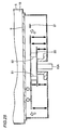
- detection path member 40 connected to hole 10A has an opening connected to hole 10A and it is provided in the form of a box.
- the form of the box corresponding to detection path member 40 has a bottom side with an infrared sensor 7 attached thereto and a detection window 11 formed therein. Through detection window 11 infrared sensor 7 senses infrared radiation in heating chamber 10.
- magnetron 12 Inside exterior 4 magnetron 12 is provided adjacent to a lower right portion of heating chamber 10. Furthermore, below heating chamber 10 a waveguide 19 is provided to connect magnetron 12 and a lower portion of body frame 5 together. Magnetron 12 supplies microwave to heating chamber 10 via waveguide 19.
- a rotative antenna 15 is provided between the bottom of body frame 5 and bottom plate 9. Under waveguide 19 is provided an antenna motor 16. Rotative antenna 15 and antenna motor 16 are connected by a spindle 15A. When antenna motor 16 is driven, rotative antenna 15 rotates.
- heating chamber 10 on bottom plate 9 a food is placed.
- Magnetron 12 generates a microwave which is in turn transmitted via waveguide 19, agitated by rotative antenna 15 and thus supplied to heating chamber 10 to heat the food on bottom plate 9.
- heating chamber 10 behind heating chamber 10 is provided a heater unit 130 housing a heater and a fan provided to efficiently transfer to heating chamber 10 the heat generated by the heater.
- a heater is also provided above heating chamber 10 to burn the surface of the food.
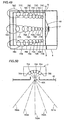
- Infrared sensor 7 includes a plurality of infrared detection elements (infrared detection elements 7A described hereinafter). Each infrared detection element has a field of view. Infrared sensor 7 can thus have a field of view considered the fields of view of the infrared detection elements that are combined together. Figs. 4 and 5 schematically illustrate a field of view of infrared sensor 7 as a total field of view 700.
- Infrared sensor 7 has a field of view covering the entirety on bottom plate 9. Thus, wherever in microwave oven 1 on bottom plate 9 a food may be placed, infrared sensor 7 is not required to move its field of view to cover the food.
- infrared sensor 7 includes a plurality of infrared detection elements.
- Fig. 6 schematically shows bottom plate 9 and infrared sensor 7. Note that in Fig. 6 a two-head arrow X corresponds to the width of microwave oven 1, a two-head arrow Y corresponds to the depth of microwave oven 1, and a two-head arrow Z corresponds to the height of microwave oven 1. Arrows X, Y and Z are orthogonal to each other.
- Infrared sensor 7 includes a total of 25 infrared detection elements 7A, five in direction Y and five in direction Z. Infrared detection elements 7A each have a field of view 70A.
- 25 infrared detection elements 7A have their respective fields of view 7A projected on bottom plate 9, on which a total of 25 fields of view 70A are projected, five in direction Y and five in direction X. Note that corresponding to five infrared detection elements 7A arranged in direction Y, on bottom plate 9 five fields of view 70A are arranged in direction Y. Furthermore, corresponding to five infrared detection elements 7A arranged in direction Z, on bottom plate 9 there are five fields of view 70A arranged in direction X.
- a single infrared detection element 7A cannot have the field of view 70A covering the entirety of bottom plate 9.
- infrared sensor 7 having 25 infrared detection elements 7A with the 25 fields of view 70A combined together allows substantially the entirety of bottom plate 9 to be covered by the field of view 70A.
- the 25 fields of view 70A combined together correspond to the total field of view 700 shown in Fig. 4 or 5.
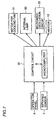
- microwave oven 1 includes a control circuit 30 generally controlling the operation of microwave oven 1.
- Control circuit 30 includes a microcomputer.
- Control circuit 30 receives various information via operation panel 6 and infrared sensor 7. Control circuit 30 uses the received information and the like to control a motor for a cooling fan, an internal lamp 32, a microwave oscillation circuit 33 and a heater 13. Motor 31 drives a fan provided to cool magnetron 12. Internal lamp 32 illuminates heating chamber 10. Microwave oscillation circuit 33 allows magnetron 12 to oscillate a microwave. Heater 13 is a heater provided in heater unit 130 and a heater provided over heating chamber 10.
- control circuit 30 receives an output of each infrared detection element 7A, individually.
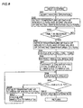
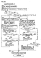
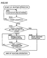
- Microwave oven 1 provides a heat-cooking process with infrared sensor 7 operating to sense the temperature of a food in heating chamber 10 to automatically terminate the heating operation. This process will now be described mainly by describing a process executed by control circuit 30.
- control circuit 3 initially at step SA1 controls magnetron 12 to start a heating operation and then moves to step SA2.
- the Figs. 6 25 infrared detection elements 7a provide their respective detection results which are in turn used to detect the temperature of the object in each field of view 70A, and the control circuit then goes to step SA3.
- the Fig. 6 25 infrared detection elements 7A are labeled P(1)-P(25), respectively, depending on their respective positions.
- P(1)-P(25) provide their respective detection results, which are in turn stored as TO(1)-TO(25).
- control circuit 30 determines whether a predetermined period of time of T in seconds has elapsed since a heating operation started at step SA1. If so then the control circuit goes to step SA4.
- control circuit 30 detects temperature based on the detection results from infrared detection elements 7A labeled P (1)-P(25) as above, and stores the values of temperature detected T(1)-T(25), and the control circuit then goes to step SA5.
- control circuit 30 calculates for each of P(1)-P(25) the difference between value T(N) stored at step SA4 immediately previously executed and TO(N) measured immediately after the heating operation is started, wherein N is 1 to 25, and the control circuit then goes to step SA6.
- control circuit 30 extracts from 25 ⁇ T(N)s calculated at step SA5 a maximal value (MAX ⁇ T1) and a second maximal value (MAX ⁇ T2) and the control circuit then goes to step SA7.
- control circuit 30 extracts from the 23 ⁇ T(N)s remaining at step SA6 a ⁇ T(N) satisfying the following expression (1), and the control circuit then goes to step SA8.
- MAX ⁇ T1 represents the maximal ⁇ T(N) extracted at step SA6 and K represents a constant satisfying 0 ⁇ K ⁇ 1.
- Microwave oven 1 provides heat-cooking processes according to a plurality of cooking menus.
- Constant K has a value varying to reflect a cooking menu to be provided.
- step SA7 (K - 2) ⁇ T(N)s satisfying expression (1) are extracted as MAX ⁇ T3 to MAX ⁇ Tk. More specifically, at steps SA6 and SA7, from 25 ⁇ T(N)s the k largest ⁇ T(N)s, i.e., MAX ⁇ T1 to MAX ⁇ Tk are extracted.
- control circuit 30 uses the following expression (2) to calculate AVE ⁇ T and then goes to step SA9.
- AVE ⁇ T corresponds to an average of temperature differences of the k largest values, as measured since the heating operation was started.
- control circuit 30 determines whether the following expression (3) is satisfied.
- expression (3) TP represents a temperature set for an object to be heated and referred to to terminate a heating operation when infrared sensor 7 senses the set temperature as the object to be heated is considered as having been sufficiently heated.
- Set temperature TP has a value set for each individual cooking menu. TO + AVE ⁇ ⁇ TP
- control circuit 30 at step SA9 determines that expression (3) is not satisfied then the control circuit goes to step SA10.
- control circuit 30 detects the current T (N) (a temperature based on an output of infrared detection element 7) at each of the k positions at which MAX ⁇ T1 to MAX ⁇ Tk are extracted at steps SA6 and SA7. The control circuit then goes to step SA11.
- control circuit 30 calculates MAX ⁇ T1 to MAX ⁇ Tk from the temperature detected at the step SA10 immediately previously performed and TO detected at steps SA2 and the control circuit then goes to step SA8.
- the SA10-SA11 steps continue until at step SA9 the control circuit determines that expression (3) is satisfied.
- step SA9 the control circuit determines that expression (3) is satisfied then at step SA12 the control circuit controls magnetron 12 to terminate the heating operation and then returns.
- control circuit 30 configures a temperature calculation unit using an output of each infrared detection element to calculate an "in field of view” temperature corresponding to a temperature of an object in a field of view of the infrared detection element, and a heating control unit referring to the "in field of view” temperature to control the heating unit.
- step SA5 ⁇ T(N) is detected for each of 25 infrared detection elements 7A, and it corresponds to a variation in "in field of view” temperature within a predetermined period of time.
- steps SA6 and SA7 MAX ⁇ T1 to MAX ⁇ Tk are extracted, and they correspond to specific variations in the predetermined period of time.
- the specific variations within the predetermined period of time include a maximal variation within the predetermined period of time and a variation within the predetermined period of time which has a value having a predetermined percentage relative to the maximal variation within the predetermined period of time.
- the fields of view 70A of k infrared detection elements 7A are subject to temperature detection, and they correspond to specific fields of view.
- the specific field of view is one of the fields of views of the multiple infrared detection elements that corresponds to a specific variation within the predetermined period of time.
- control circuit 30 refers to the "in field of view” temperatures in the specific fields of view to control the heating unit.
- infrared sensor 7 has 25 infrared detection elements 7A arranged in a 5 ⁇ 5 matrix and having the fields of view 70A each corresponding to a different area on bottom plate 9 to together cover substantially the entirety of bottom plate 9. In other words, wherever on bottom plate 9 a food may placed, the food can be covered by at least one of the 25 fields of view 75A.
- the plurality of infrared detection elements are not required to move their fields of view to cover at least a portion of the food placed in the heating chamber.
- an area having experienced a largest temperature variation since a heating operation started i.e., an area in which MAX ⁇ T1 is detected
- an area having experienced a largest temperature variation since a heating operation started i.e., an area in which MAX ⁇ T1 is detected
- an area having experienced a second largest temperature variation since the heating operation started i.e., an area in which MAX ⁇ T2 is detected
- an area having experienced a second largest temperature variation since the heating operation started is also considered as bearing a food thereon and thus has its temperature continuously detected until the heating operation ends (steps SA8-SA11).
- step SA7 if an area has a temperature variation relative to the largest temperature variation that is equal to or exceeds a predetermined percentage (K, see step SA7), then the area also has its temperature continuously detected until the heating operation ends (steps SA8-SA11).
- the present embodiment is not limited as above.
- step SA6 is changed to extract only MAX ⁇ T1 and furthermore at step SA7 are extracted (k-1) values, MAX ⁇ T2 to MAX ⁇ TK.
- infrared sensor 7 includes a plurality of infrared detection elements 7A, it is not a requirement that bottom plate 9 has substantially any area thereof covered by the field of view 70A of infrared detection element 7A, as shown in Fig. 6.
- infrared sensor 7 including a plurality of infrared detection elements 7A arranged in a predetermined direction in a line will now be described by way of example.
- infrared sensor 7 has infrared detection elements 7A arranged in a line in the direction of the depth of heating chamber 10, although not shown in the figure.
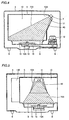
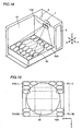
- exterior 4 and door 3 are omitted and so is a portion of body frame 5 corresponding to a left-side wall of heating chamber 10, to allow heating chamber 10 to have it interior readily visually observed.
- axes X, Y and Z are defined to correspond to the width, depth and height of heating chamber 10, respectively. These three axes are orthogonal to each other.
- microwave oven 1 includes infrared sensor 7 having six infrared detection elements 7A arranged in direction Y and in addition to the Figs. 1 and 7 microwave oven 1 a sensor motor 7Z is provided to move a field of view of infrared detection element 7A, (see Fig. 9B).
- bottom plate 9 With infrared sensor 7 having six infrared detection elements 7A, on bottom plate 9 are simultaneously projected six fields of view 70A arranged in direction Y, as represented by solid lines. Bottom plate 9 is covered by six fields of view 70A in direction X at an area extending in direction Y from one end to the other end.
- microwave oven 1 is also provided with a member (sensor motor 7Z) capable of moving infrared sensor 7 in the direction indicated by a two-head arrow 93 corresponding to a direction of rotation on the X-Z plane.
- Sensor motor 7Z operates as controlled by control circuit 30.
- infrared detection element 7A also positionally moves and the field of view 70A projected on bottom plate 9 thus has a position moving in a direction indicated by a two-head arrow 91 (i.e., in direction X). More specifically, moving infrared sensor 7 in direction 93 allows the field of view 70A to move from a position indicated by the solid line to a position indicated by the broken line.
- the number of infrared detection elements 7A is not limited to any particular number and there exist N fields of view 70A aligned in direction Y.
- the field of view 70A can take M positions as it moves in direction X. More specifically, if a coordinate system P (X, Y) is applied, then on bottom plate 9 the field of view 70A has a position represented by P (1, 1) to P (M, N).
- the plurality of infrared detection elements 7A have their respective fields of views arranged to simultaneously cover bottom plate 9 in direction Y from one end to the other end.
- the plurality of infrared detection elements 7A have their fields of view in the coordinate system P (X, Y) with a coordinate X having a uniform value and a coordinate Y having N values ranging from one to N.
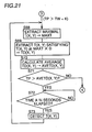
- control circuits 30 When operation panel 6 is used to provide a heat-cooking operation, control circuits 30 initially at S 1 controls magnetron 12 to start a heating operation.
- control circuit 30 moves infrared sensor 7 to allow infrared detection elements 7A to have their fields of view 70A having coordinate X equal to one.
- control circuit 30 uses outputs of the infrared detection elements for the current positions of their fields of view 70A to detect the temperature of an object in the fields of view 70A, and stores detected temperatures TO(X, 1) to TO(X, N).
- TO(X, 1) to TO(X, N) each have value X substituted by the value of the current coordinate X of a respective one of the fields of view 70A.
- control circuit 30 increments the value of coordinate X of each field of view 70A by one to update it. This moves coordinate X of the field of view 70A to the position of coordinate X resulting from the increment.
- control circuit 30 determines whether the value of coordinate X obtained at S4 exceeds M. If not then the control circuit returns to S3 and if so then the control circuit moves to S6. Thus the S3 and S4 steps continue until the field of view 70A having coordinate X of one attains that of M. Thus bottom plate 9 has its entirety covered N ⁇ M fields of view 70A.
- control circuit 30 moves infrared sensor 7 to allow infrared detection element 7A to each have a field of view 70A with a coordinate X equal one.
- the outputs from the infrared detection elements for the current positions of the fields of view 70A are used to detect the temperature of an object in each field of view 70A and detected temperatures T(X, 1) to T(X, N) are stored.
- control circuit 30 increments the value of coordinate X of each field of view 70A by one to update it.
- control circuit 30 determines whether the value of coordinate X obtained at S9 exceeds M. If not then the control circuit returns to S8 and if so then the control circuit moves to S11. Thus the S8 and S9 steps continue until the fields of view 70A having coordinate X of one attains coordinate X of N.
- control circuit 30 uses TO(1, 1) to TO(M, N) stored at S3 and T(1, 1) to T(M, N) stored at S8 to calculate ⁇ T(X, Y) for each coordinate and then move to S12. More specifically, at S11 are calculated N ⁇ M ⁇ T(X, Y)s.
- control circuit 30 extracts a maximal one of N ⁇ M ⁇ T(X, Y)s and stores it as MAX ⁇ T(X, Y).
- control circuit 30 extracts any of N ⁇ M ⁇ T(X, Y)s calculated at S11 that satisfy the following expression (5) and stores the same as TA(X, Y).
- K represents a constant satisfying 0 ⁇ K ⁇ 1 and varies in value to reflect a cooking menu to be executed.
- the position of the field of view 70A corresponding to ⁇ TA(X, Y) will be referred to as a "specific position.”
- control circuit 30 calls for temperature TO(X, Y) detected immediately after the heating operation is started that is stored at S3 and control circuit 30 provides it as TAO(X, Y) and calculates an average thereof (AVETAO(X, Y)) and stores the average as TAO.
- control circuit 30 calculates an average AVE ⁇ TA(X, Y) of ⁇ TA(X, Y)s extracted at S13 and stores the average as ⁇ TA.
- control circuit 30 determines whether TAO calculated at S14 plus ⁇ TA calculated at S15 attains TP. If not then the control circuit moves to S17 and if so then the control circuit goes to S19.
- TP represents a temperature set for an object to be heated, adopted to terminate a heating operation when the temperature is attained as the object to be heated is considered as having been sufficiently heated.
- control circuit 30 controls magnetron 12 to terminate the heating operation and the control circuit thus ends the heat-cooking process and returns.
- control circuit 30 detects temperature at a specific position (referred to as a coordinate PA(X, Y)) extracted at S13 as TA(X, Y).
- control circuit 30 calculates for each specific position a difference ⁇ TA(X, Y) between temperature detected at the immediately previously executed S17 and that detect at S3 and then returns to S15.
- temperature detection within the field of view 70A is provided on bottom plate 9 at N ⁇ M areas labeled P (1, 1) to P (M, N). Note that the temperature detection at each of N ⁇ M areas is provided immediately after a heating operation is started (S2-S5) and when a predetermined period of time has elapsed since the heating operation was started (S7-S10).
- temperature variation is calculated for a predetermined period of time (T in seconds) elapsing after the heating operation is started and it is provided as ⁇ T(1, 1) to ⁇ T(M, N) (S11).
- ⁇ TA(X, Y) having a value having at least a predetermined percentage of K relative to maximum value MAX ⁇ T(X, Y) (S12, S13).
- MAX ⁇ T(X, Y) is a maximal value of ⁇ T(1,1) to ⁇ T(M, N) and ⁇ TA(X, Y) includes MAX ⁇ T(X, Y).
- N ⁇ M areas on bottom plate 9 an area corresponding to extracted ⁇ TA(X, Y) is referred to as a "specific position" for the sake of convenience.
- TAO is calculated as an average of temperatures TAO(X, Y)s for specific positions that are measured when a heating operation is started (S14).
- ⁇ TA is calculated as an average of temperature elevations ⁇ TA(X, Y)s at the specific positions. Whether TAO plus ⁇ TA exceeds set temperature TP is referred to to determine whether the heating operation should be terminated (S16).
- an area having experienced a largest temperature variation since a heating operation was started is considered as bearing a food thereon and its temperature is continuously detected until the heating operation ends. Furthermore, if an area has a temperature variation having at least a predetermined percentage (K, see S13) relative to the largest temperature variation the area also have its temperature continuously detected until the heating operation ends.
- the area with the largest temperature variation and that with the temperature variation of at least a predetermined percentage relative to the largest temperature variation are generally referred to as a "specific area.”
- the plurality of infrared detection elements 7A has their fields of view 70A combined together to cover bottom plate 9 in direction X (the direction of the width of heating chamber 10) in an area in direction Y (the direction of the depth of heating chamber 10) from one end to the other end. Furthermore, in the present variation, as has been described with reference to Figs. 9 and 10, the field of view 70A moves in direction X.
- infrared detection elements 7A may be provided to allow fields of view 70A to together cover bottom plate 9 in X direction from one end to the other end and also move in direction Y. More specifically, with reference to Figs. 12 and 13, in heating chamber 10 the plurality of fields of view 70A moves in the direction of a two-head arrows 99, i.e., direction Y. Thus, if a field of view has a position represented in an X-Y coordinate system by P(X, Y), fields of view located at P(1, N) to P(M, N) moves to change their coordinates Ys.
- the plurality of infrared detection elements 7A may not be provided to allow the fields of view 70A to cover bottom plate 9 in direction Y or X from one end to the other end.
- a description will be made of a microwave oven of a second variation, including a plurality of infrared detection elements 7A having their fields of view 70A smaller in size than bottom plate 9 in both directions X and Y when the fields of view are combined together.
- infrared sensor 7 includes five infrared detection elements 7A arranged in a line in the direction of the depth of heating chamber 10, although not shown in the figure.
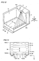
- Fig. 14 omits various components of microwave oven 1 to allow heating chamber 10 to have its interior readily, visually observed.
- heating chamber 10 has its width, depth and height defined to correspond to three axes X, Y and Z orthogonal to each other. Note that Fig. 14 shows in heating chamber 10 axes X and Y in the form of broken lines X and Y, traversing each other at the center of turntable 90. An arrow 92 indicates a direction in which turntable 90 rotates.
- microwave oven 1 includes heating chamber 10 having a bottom side provided with a round turntable 90.
- microwave oven 1 is preferably configured to have magnetron 12 supplying heating chamber 10 with microwave at a side surface of heating chamber 10. Accordingly, waveguide 19 and rotative antenna 15 are preferably attached to the side surface of heating chamber 10.
- infrared detection elements 7A are arranged to have their fields of view 70A aligned in direction Y.
- Five fields of view 70A projected on turntable 90 that are combined together are successively projected from the center of turntable 90 to a periphery thereof. As such, when turntable 90 turns, turntable 90 has its entire area covered by five fields of view 70A.
- the number of infrared detection elements 7A is not limited to any particular number to generally describe microwave oven 1 including infrared detection elements 7A arranged in the direction of the depth of heating chamber 10, and there thus exist N fields of view 70A arranged in direction Y.
- the field of view 70A can have a position, if represented by P(N), of P(1) to P(N).
- P(1) corresponds to the center of turntable 90 and as the number in the parenthesis increases the position represented by P(N) approaches a periphery of turntable 90, and P(N) corresponds to an outermost peripheral position of turntable 90.
- control circuit 30 When operation panel 6 is operated to provide a heat-cooking process, control circuit 30 initially at S20 controls magnetron 12 to start a heating operation and the control circuit then goes to S21.
- control circuit 30 detects a temperature based on an output of each infrared detection element 70A having its fields of view 70A at a respective one of positions P(1) to P(N).
- Control circuit 30 associates the temperatures detected at S21 with position P (1) to P (N), respectively, and stores them as T (1) to T (N). Furthermore, control circuit 30 also stores as TW a detected temperature T(N) corresponding to position P(N), at which the temperature is detected.
- control circuit 30 determines whether TW minus K (°C) is greater than TP. If so then the control circuit goes to S23 and if not then control circuit 30 goes to S40.
- control circuit 30 determines whether TW plus K (°C) is smaller than TP. If so then the control circuit goes to S41 and if not then the control circuit goes to S30.
- TP is a temperature set for an object to be heated, adapted to terminate a heating operation when the temperature is attained as the object to be heated is considered as having being sufficiently heated.
- K represents a constant of approximately five. That is, K°C is approximately 5°C. If microwave oven 1 provides a heat-cooking process to reflect multiple cooking menus, K is set for each of the menus.
- control circuit 30 sets a value of "1" on axis Y for a location at which is detected a temperature to be extracted at 24 to be subject to a decision. More specifically, at S23 control circuit 30 provides a setting to allow T(1) to be subject to a decision at S24.
- control circuit 30 extracts a detected temperature T(Y) currently set to be subject to a decision and determines whether the temperature is lower than set temperature TP. If so then the control circuit goes to S25 and if not then the control circuit goes to S27.
- a detected temperature subject to a decision at S24 is that obtained from those obtained at the immediately previously executed S21 or S29 step which is detected at a location set at the immediately previously executed S23 or S26 step.
- control circuit 30 determines whether a position on axis Y currently set to be extracted as a subject for decision is no more than N - 1. If so then the control circuit goes to S26. If not, i.e., if it has attained N then the control circuit goes to S28.
- control circuit increments the currently set location by one on axis Y to update it and the control circuit then returns to S24. More specifically, the control circuit continues to make the S24 decision until a position having a value "1" on axis Y attains a value of "N" on the axis.
- control circuit 30 determines whether a predetermined period of time A in seconds has elapsed since T I -T N were detected at the immediate previous S29 or S21, and if so then the control circuit goes to S29.
- temperature is detected at each of locations P(1) to P(N - 1) and stored as new values T (1) to T (N - 1) and the control circuit then goes to S23.
- T(1) to T(N - 1) is detected I times whenever turntable 90 rotates once. More specifically, temperature is detected on turntable 90 at a position of a radius forming an angle of 360 / I to each other.
- control circuit 30 at S27 determines whether TY is smaller than TW. If the control circuit determines that TY is no less than TW then the control circuit returns to S25. If the control circuit determines that TY is smaller than TW then the control circuit at S39 controls magnetron 12 to terminate the current heating operation and the control circuit returns.
- control circuit 30 sets a value of "1" on axis Y for a location of at which is detected a temperature subject to a decision to be made at S31 to be subsequently executed.
- control circuit 30 extracts detected temperature (TY) currently set to be subject to a decision and control circuit 30 determines whether the temperature is lower than set temperature TP minus K, i.e., TW - K. If so then the control circuit goes to S32 and if not then the control circuit goes to S34.
- detected temperature TY subject to a decision at S31 is that obtained from those obtained at the immediately previously executed S21 or S38 step.
- TW is T(N) detected at S21 which is detected at a location set at the immediately previously executed S30 or S33 step.
- control circuit 30 determines whether a location on axis Y that is currently set to be extracted as a subject for a decision is no more than N - 1. If so then the control circuit 30 goes to S33. If not then the control circuit goes to S37.
- control circuit 30 increments the currently set location by one on axis Y to update it and the control circuit then goes back to S31. More specifically, the control circuit continues to make the S31 decision until a location having a value "1" on axis Y attains a value of "N" on the axis.
- control circuit determines whether a predetermined period of time A in seconds has elapsed since T(1) to T(N) were detected at the immediate previous S38 or S21 and if so then the control circuit goes to S38.
- temperature is detected at each of location P(1) to P(N - 1) and stored new T(1) to T(N -1) and the control circuit goes back to S33.
- time A in seconds is similar to that as has been described in the S28 step, i.e., a period for detecting T(1) to T(N - 1).
- control circuit 30 determines that TY has attained TW - K then control circuit 30 goes to S24 and determines whether TY is lower than TW. If TY is no less than TW then the control circuit goes back to S32 and if TY is lower than TW then the control circuit goes to S35.
- control circuit 30 determines whether TP is lower than TW and if so then control circuit 30 at S39 controls magnetron 12 to terminate the current heating operation and the control circuit returns.
- control circuit 30 at S36 controls magnetron 12 to provide a further heating operation from that time point for an additional temporal period corresponding to value K in the process of interest and the control circuit at S39 terminates the heating operation and returns.
- K is a value previously determined to correspond to a cooking menu.
- a heating operation is additionally executed for a period of time corresponding to a cooking menu.
- control circuit 30 sets a value of "1" on axis Y for a location at which is detected a temperature to be extracted to be subject to the subsequent S42 decision.
- control circuit 30 extracts detected temperature (TY) currently set to be subject to a decision and the control circuit determines whether the temperature is lower than set temperature TP. If so then the control circuit goes to S43 and if not then the control circuit at S39 terminates the heating operation and returns.
- TY detected temperature
- a detected temperature subject to the S42 decision is that obtained from those obtained at the immediately previously executed S21 or S46 step which is obtained at a location set at the immediately previously executed S41 or S44 step.
- control circuit 30 determines whether a location on axis Y that is currently set to be extracted as a subject for a decision is no more than N - 1. If so then the control circuit goes to S44. If not then the control circuit goes to S45.
- control circuit 30 increments the currently set position by one on axis Y to update it and then goes back to S42. More specifically, the control circuit continues to make the S42 decision until a position having a value "1" on axis Y attains a value of "N" on the axis.
- control circuit determines whether a predetermined period of time A in seconds has elapsed since T(1) to T(N) were immediately previously detected at S46 or S21. If so then the control circuit goes to S46.
- temperature is detected for each of locations P(1) to P(N - 1) and stored as new T(1) to T(N - 1) and then goes back to S41.
- time A in seconds is a period for detecting T(1) to T(N - 1).
- a heat-cooking process provides different blocks of steps to reflect value TW, as provided on Table 1.
- temperature is detected whenever time A in seconds elapses.
- Time A in seconds, a period for temperature detection, and revolution rate B (bpm) are preferably have a relationship as represented by expression (6) provided above.
- microwave oven 1 includes infrared detection elements 7A having the fields of view 70A that cannot cover the entire bottom side of heating chamber 10 at a time even if all of the fields of view are combined together.
- the heating chamber 10 bottom side has turntable 90, which turns to allow substantially any area on turntable 90 to be covered by one of the fields of view 70A of the multiple infrared detection elements 7A.
- microwave oven 1 As a further variation of microwave oven 1, a description will now be made of a microwave oven including heating chamber 10 having a bottom side provided with a turntable and having its area substantially entirely covered by the fields of view 70A of multiple infrared detection elements 7A at a time such that the chamber's bottom side has any portion thereof covered by one of the fields of view 70A of multiple infrared detection elements 7A.
- infrared sensor 7 includes infrared detection elements 7A arranged in a M ⁇ N matrix in the directions of the depth and height of heating chamber 10, although not shown in the figure.
- microwave oven 1 is shown with various components omitted to allow heating chamber 10 to have its interior readily visually observed.
- heating chamber 10 has its width, depth and height defined to correspond to three axes X, Y and Z orthogonal to each other.
- microwave oven 1 has heating chamber 10 having a bottom side provided with a round turntable 90. Accordingly, microwave oven 1 preferably has magnetron 12 supplying heating chamber 10 with microwave at a side wall of heating chamber 10 and also has waveguide 19 and rotative antenna 5 attached to the side wall of heating chamber 10.
- M infrared detection elements 7A in direction Y and N infrared detection elements 7A in direction Z there exist M infrared detection elements 7A in direction Y and N infrared detection elements 7A in direction Z. Accordingly, on the heating chamber 10 bottom side are projected M fields of view 70A (six of them in Fig. 18 by way of example) in direction Y and N fields of view 70A in direction X. Some of M ⁇ N fields of view 70A are projected on turntable 90 and the other thereof are projected outside turntable 90. Note that turntable 90 has any portion thereof covered by one of M ⁇ N fields of view 70A.
- the field of view 70A has a position represented in the form of "P(X, Y)" then it can have a position represented by P(1, 1) to P(N, M).
- P (1, 1) represents a deepest, rightmost position in heating chamber 10 (an upper right corner in Fig. 19)
- P(N, M) corresponds to a front, leftmost corner in heating chamber 10 (a lower left corner in Fig. 19).
- the field of view 70A closer to the left side as seen in direction X has a larger coordinate X and that closer to the front side (the lower side in Fig. 19) as seen in direction Y has a larger coordinate Y.
- control circuit 30 When operation panel 6 is operated to provide a heat-cooking operation, control circuit 30 initially at S49 controls magnetron 12 to start a heating operation.
- control circuit 30 detects temperature based on outputs of infrared detection elements 70A having their respective fields of view 70A at positions P(1, 1) to P(N, M), respectively.
- control circuit 30 associates M ⁇ N temperatures detected at S50 with positions P(1, 1) to P(N, M), respectively, and stores them as T(1, 1) to T(N, M).
- control circuit 30 also stores as TW a detected temperature T(1, 1) corresponding to position P(1, 1).
- control circuit 30 determines whether TW minus K (°C) is greater than TP and if so then the control circuit goes to S53 and if not then the control circuit goes to S52.
- control circuit 30 determines whether TW plus K (°C) is smaller than TP and if so then the control circuit goes to S68 and if not then the control circuit goes to S60.
- TP is a temperature set for an object to be heated, adapted to terminate a heating operation when the temperature is attained as the object to be heated is considered as having been sufficiently heated.
- K is a constant of approximately five. That is, K°C is approximately 5°C. If microwave oven 1 provides a heat-cooking operation to accommodate various cooking menus K is set for each cooking menu.
- the heat-cooking process follows the process steps following S53 that are divided generally into three blocks S53-S59, S60-S66, and S68-S73. Which block of steps control circuits 30 is to execute depends on the magnitude of TW at the S51 and S52 decisions.
- Table 2 represents a relationship between TW and the blocks executed by control circuit 30. Table 2 TP + K ⁇ TW (TP ⁇ TW - K) TP - K ⁇ TW ⁇ TP + K (TW - K ⁇ TP ⁇ TW + K) TP - K > TW (TP > TW + K) Steps to be Executed S53-S59 S60-S66 S68-S73
- control circuit 30 extracts any of T(X, Y), or T(1, 1) to T(N, M), detected at the immediately previously executed S50 or S59 step that is lower than TW plus K (°C) and the control circuit provides it as TE(X, Y) and then goes to S54.
- control circuit 30 extracts a maximal one of TE(X, Y)s extracted at S53 and stores it as MAXTE.
- control circuit 30 extracts any of TE(X, Y)s that has a temperature no less than the product of MAXTE and a constant D and stores it has TED(X, Y). Note that D represents a constant previously determined for each cooking menu and satisfying 0 > D > 1.
- control circuit 30 calculates an average of TED(X, Y)s extracted at S55 and stores it as AVETED(X, Y).
- control circuit 30 determines whether AVETED(X, Y) calculated at S56 is lower than TP and if so then the control circuit goes to S58 and if not then the control circuit at S67 controls magnetron 12 to terminate the heating operation and returns.
- control circuit 30 determines whether time A in seconds has elapsed since T(X, Y) was detected at the immediately previously executed S59 or S50 step and if so then the control circuit goes to S59.
- temperature is detected for each of positions P(1, 1) to P(N, M) and stored as new T(1, 1) to T(N, M) and then the control circuit returns to S53.
- time A in seconds correspond to a period for detecting T(1, 1) to T(N, M).
- turntable 90 has a revolution rate of B (bpm)
- T(1, 1) to T(N, M) is detected I times whenever turntable 9 turns once. More specifically, temperature is detected on turntable 90 at a location of a radius forming an angle of 360 / I to each other.
- control circuit 30 extracts any of T(X, Y), or T (1,1) to T(N, M), detected at the immediately previously executed S50 or S64 step that is no less than TW minus K (°C) and the control circuit provides it as TF(X, Y).
- control circuit 30 extracts any of TE(X, Y) extracted at S60 that is lower than TW and the control circuit stores it as TFT(X, Y).
- control circuit 30 determines whether there is no TFT(X, Y) extracted at S61 and if so then the control circuit goes to S63 and if not then the control circuit goes to S65.
- control circuit 30 determines whether a predetermined temporal period A in seconds has elapsed since T(X, Y) was detected at the immediately previously executed S64 or S50 step and if so then the control circuit goes to S64.
- temperature is detected for each of positions P(1, 1) to P(N, M) and stored as new T(1, 1) to T(N, M) and the control circuit then goes back to 560.
- time A in seconds correspond to a period for detecting T(1, 1) to T(N, M), as has been described in the S58 step.
- control circuit 30 determines whether TP is lower than TW and if so then the control circuit at S67 controls magnetron 12 to terminate the heating operation and then returns.
- control circuit 30 at S65 determines that TP is greater than TW then control circuit 30 at S66 controls magnetron 12 to provide an additional heating operation from that time for an additional temporal period corresponding to value D in the process of interest and the control circuit then at S39 terminates the heating operation and returns.
- D represents a value previously determined to correspond to a cooking menu.
- an additional heating operation is executed for a temporal period corresponding to a cooking menu.
- control circuit 30 extracts a maximal one of T(X, Y), or T(1, 1) to T(N, M), detected at the immediately previously executed S50 or S59 step and provides it as MAXT.
- control circuit 30 extracts any of T (X, Y)s detected at the immediately previously executed S50 or S69 that has a value exceeding the product of MAXT and constant D, and control circuit 30 stores it as TD(X, Y).
- D represents a constant previously determined for each cooking menu, as has been described in S55.
- control circuit 30 calculates an average of TD(X, Y)s extracted at S69 and stores it as AVETD(X, Y).
- control circuit 30 determines whether AVETD(X, Y) calculated at S70 is higher than TP and if so the control circuit goes to S72 and if not then the control circuit at S67 controls magnetron 12 to terminate the heating operation and the control circuit returns.
- the control circuit determines whether a predetermined temporal period A in seconds has elapsed since T(X, Y) was detected at the immediately previously executed S73 or S50 step and if so then the control circuit goes to S73.
- temperature is detected for each of positions P(1, 1) to P(N, M) and stored as new T(1, 1) to T(N, M) and the control circuit then returns to S68.
- Time A in seconds is a period for detecting T(1, 1) to T(N, M).
- a heat-cooking process provides different blocks of steps to reflect value TW, as has been provided in Table 2.
- temperature is detected whenever time A in seconds elapses.
- the temperature detection period of A in seconds and revolution rate B (bpm) preferably have a relationship as represented by equation (7) provided above.
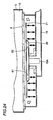
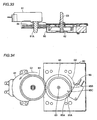
- Fig. 22 is a partial cross section of a microwave oven corresponding to Fig. 4.
- the present variation provides a microwave oven having heating chamber 10 overlying a rotative antenna 20 rather than rotative antenna 15.
- a subantenna 21 is attached to rotative antenna 20. Furthermore, with reference to Fig. 23, rotative antenna 20 and subantenna 21 are each provided in the form of a plate. Subantenna 21 is attached to rotative antenna 20 by an insulator 61, 62. That is, rotative antenna 20 and subantenna 21 are insulated from each other. Note that rotative antenna 21-is attached to spindle 15A. at the top end
- a switch 89 switched on once whenever spindle 15A revolves once. The revolution of spindle 15A is transferred to switch 89 via a well known mechanism provided in a box 88.
- a thin arrow and a white arrow each represent a microwave radiation pattern and a thick, two-head arrow represents a pattern in which an electrical field is generated.
- a microwave guided from magnetron 12 via waveguide 19 is transmitted through rotative antenna 20 and radiated therefrom at a perimeter (as indicated in Figs. 24 and 25 by thin arrows) and also transmitted between a periphery of rotative antenna 20 and a bottom side of body frame 5 and between subantenna 21 and a bottom side of body frame 5 (as indicated in Figs. 24 and 25 by thick, two-head arrows) and thus radiated in a vicinity of a periphery of subantenna 21 (as indicated in Figs. 24 and 25 by white arrows).
- the distance from the top end of spindle 15A to the peripheral edge of rotative antenna 20 is preferably set to be one half of the wavelength of the microwave or that plus the wavelength of the microwave that is multiplied by an integer, since rotative antenna 20 thus dimensioned can peripherally have an electrical field having an intensity of a maximal value or a value closer thereto.
- subantenna 21 can be formed to correspond to the geometry of hating chamber 10 receiving microwave radiation.
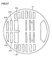
- Subantenna 21 is provided with a plurality of holes, as will be described hereinafter, and Fig. 25 shows that an electronic wave propagates through a hole of subantenna 21.
- An electronic wave transmitted from waveguide 19 is in turn transmitted via spindle 15A to the center of rotative antenna 20 and therefrom toward an edge of rotative antenna 20.
- Some of the electronic wave transmitted to the edge of rotative antenna 20 is supplied directly into heating chamber 10 and the other thereof is transmitted to subantenna 21.
- Some of the electronic wave transmitted to subantenna 21 is supplied from an edge of subantenna 21 to heating chamber 10 and the other thereof is supplied from an edge of a hole 8(holes 21A to 21F described hereinafter) to heating chamber 10.
- rotative antenna 20 is generally covered by subantenna 21. More specifically, subantenna 21 has a periphery outer than rotative antenna 20, Thus, subantenna 21 exists closer to heating chamber 10 than rotative antenna 21 and, as seen in a plane parallel to that opposite to heating chamber 10, has a large geometrical dimension and also exists over a large area. This can supply heating chamber 10 with a microwave over an area larger than when there is only rotative antenna 20. Reference will now be made to Fig. 26 to describe further in detail an effect of providing such a subantenna 21.
- rotative antenna 15 has a periphery radiating a microwave toward heating chamber 10 only in a vicinity of the center.
- rotative antenna 20 and subantenna 21 are both provided, as shown in Figs. 24 and 25, then not only does rotative antenna 20 have a periphery radiating a microwave toward heating chamber 10 in a vicinity of the bottom center but subantenna 21 also has a periphery radiating a microwave toward heating chamber 10 in a vicinity of the corner.
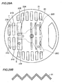
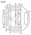
- subantenna 21 is provided with a plurality of holes including holes 21A to 21F.
- subantenna 21 having received an electronic wave from rotative antenna 20 can radiate a microwave not only from an outer peripheral edge but from the holes.
- subantenna 21 Since subantenna 21 is fixed to rotative antenna 20, it can revolve in the same period as rotative antenna 20. As such, subantenna 21 can supply heating chamber 10 with a microwave in a pattern that varies as subantenna 21 rotates. More specifically, rotating subantenna 21 allows heating chamber 10 to be supplied with a microwave in a more complicated pattern, i.e., uniformly.
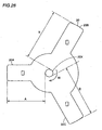
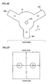
- Rotative antenna 20, as shown in Fig. 28, has a center provided with a hole 20X to be connected to spindle 15A. Furthermore, rotative antenna 20 also has portions 20A to 20C extending from hole 20X radially. In a vicinity of hole 20X, rotative antenna 20 has an accurate periphery. Portion 20A has an end spaced from hole 20X by a distance A of approximately 60 mm and portions 20B and 20C each have an end spaced from hole 20X by a distance D of approximately 80 mm. Distance A corresponds to approximately one half in length of the wavelength of a microwave.
- An end of rotative antenna 20 radiates a microwave having an intensity depending on that of an electrical field generated at the edge.
- the intensity of the electrical field depends on the distance from a magnetron antenna of magnetron 12 to spindle 15A, the distance from an end of spindle 15A to a peripheral edge of rotative antenna 20, the relationship between the length and geometry of waveguide 19 and the wavelength of a microwave radiated, and the like.
- the portion 20a edge radiates a microwave more intense than the portions 20B and 20C edges.
- a waveguide is typically designed to intensify an electrical field generated in a vicinity of a power feed port of the waveguide, i.e., in a vicinity of spindle 15A.
- the edge has a more intense electrical field. If the length is dimensioned closer to one fourth of the wavelength of a microwave that is multiplied by an odd number, then the edge has a weak electrical field.
- subantenna 21 in a vicinity of portion 20A has holes 21A-21E in the form of a slit having its longitudinal direction perpendicular to a main direction in which a microwave propagates (as indicated by an arrow E in Fig. 20A).
- Holes 21A to 21F allow an intense microwave to be radiated.
- Holes 21B, 21D, 21E and 21F allow a significantly intense microwave to be radiated.
- these holes 21B, 21D, 21E and 21F has a longitudinal dimension set to be approximately 55 mm to 60 mm.
- bottom plate 9 is for example transparent to allow subantenna 21 to be visible in heating chamber 10 and such is displayed in a vicinity of an area having holes 21A to 21F formed therein (an area F in Fig. 29A), for example by using characters, such as "power zone", to indicate that in that in the zone a food is intensively heated, or by corrugating a surface of the area, i.e., having a cross section as shown in Fig. 29B.
- rotative antenna 20 is attached to spindle 15A at the top end that is crimped polygonal rather than round as seen in cross section.
- hole 20X has a cross section in the form of an octagon.
- Axis 15A crimped to be polygonal as seen in cross section can prevent rotative antenna 20 from sliding relative to spindle 15A when spindle 15A is rotated to rotate rotative antenna 20 in a direction W. In other words, controlling an angle at which spindle 15A rotates reliably controls an angle at which rotative antenna 20 rotates.
- rotative antenna 20 is provided with subantenna 21 insulated therefrom and rotative antenna 20 also configures a radiation antenna.
- rotative antenna 20 in dimension, however, imposes limitations on designing the heating chamber for example because: (1) a microwave is mostly radiated from rotative antenna 20 at an edge; (2) as rotative antenna 20 increases in dimension, microwave transmission loss also increases; and (3) to allow rotative antenna 20 to radiate a microwave efficiently, the antenna is required to have a dimension in relation to the wavelength of the microwave and the heating chamber thus cannot be sized as desired (for example, to allow the rotative antenna 20 edge to radiate a microwave with a maximal output, the length from spindle 15A to the rotative antenna 20 edge is required to be closer to one fourth of the wavelength of the microwave that is multiplied by an even number.
- subantenna 21 only functions to a periphery of subantenna 21 a portion of a microwave radiated from rotative antenna 20 and its dimension does not contribute to transmission loss.
- subantenna 21 can be dimensioned as desired regardless of microwave radiation efficiency.
- rotative antenna 20 can be designed with a most efficient dimension and its edge can radiate a microwave and a portion of the radiated microwave can also be guided through subantenna 21, dimensioned as desired, to a periphery thereof and thus radiated therefrom.
- subantenna 21 is only required to have a dimension to consider the size of the heating chamber, which allows the heating chamber to be sized as desired.
- the heating chamber can receive a microwave radiated in a vicinity of an edge of rotative antenna 20 and a periphery of subantenna 21, rotating rotative antenna 20 and subantenna 21 can supply the heating chamber with a microwave radiated more uniformly.
- subantenna 22 is subantenna 21 of the fourth variation plus a reflector 22X.
- a microwave oven includes an optical sensor 23 attached under body frame 5.
- Optical sensor 23 includes a light directing element and a light receiving element.
- the light directing element radiates light as indicated by an arrow V1 at intervals of a predetermined temporal period.
- Rotative antenna 20 and subantenna 22 fixed to rotative antenna 20 are rotated by driving a motor 81.
- the sensor's light receiving element detects a reflection of light V1 that is provided by reflector 22X, as indicated by an arrow V2. From the detection of light V2 by optical sensor 23 is derived that rotative antenna 20 and subantenna 22 have a predetermined position as they rotate. Furthermore, detecting a timing as counted from the time point when optical sensor 23 detects light V2, allows detecting the position of rotative antenna 20 and subantenna 22 as they rotate.
- switch 89 as described in the fourth variation can be dispensed with and rotative antenna 20 and subantenna 22 can have their conditions directly detected as they rotate.
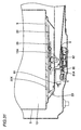
- motor 81 provided to rotate spindle 15A connected to rotative antenna 20 is attached at a (left) side of spindle 15a, rather than under the spindle.
- motor 81 has a spindle 81A which is in turn connected to a cam 84.
- the cam 84 rotation is transferred to a cam 82 and the cam 82 rotation is transferred to a spindle 83 and the spindle 83 rotation is transferred to spindle 15A (see Fig. 31).
- spindle 81A rotates and its rotation is transferred via cams 84 and 82 and spindle 83 to spindle 15A.
- motor 81 is arranged at a side of spindle 15A.
- motor 81 has a position that does not overlap a passage of food juice dropping from heating chamber 10 that is expected under heating chamber 10, as indicated in Fig. 31 by arrows.
- food juice dropping in heating chamber 10 should move downward to under heating chamber 10 and long spindle 15A, it cannot reach motor 81.
- the present variation provides a microwave oven corresponding to that of the fifth variation with cam 82 (see Figs. 31 and 33) replaced by a came 85 having a periphery close to a switch 86 having a switch button 86a pressed to switch a predetermined circuit on/off.
- reflector 22X is employed to detect the conditions of subantenna 22 and rotative antenna 20 as they rotate.
- the condition of cam 85 as it rotates is detected to detect the conditions of subantenna 22 and rotative antenna 20 as they rotate.
- cam 85 The condition of cam 85 as it rotates is detected, as will now be described.
- G1 denotes a direction in which cam 84 rotates
- G2 denotes that in which cam 85 rotates.
- Cam 85 is basically round in geometry, although it has a protrusion 85C.
- Protrusion 85C is adjacent in the direction of rotation to a portion 85A, which suddenly reduces in distance, as measured from the center (spindle 83), as it moves farther away from portion 85C.
- Portion 85C is also adjacent in the opposite direction of rotation to portion 85B, which reduces in distance, as measured from the center (spindle 83), more gradually than portion 85A. If cam 85 having such a peripheral geometry rotates in a direction G2, it can quickly press switch pattern 86A with portion 85A and gradually release it with portion 85B.
- switch 86 can detect those of rotative antenna 20 and subantenna 22 as they rotate. In doing so, switch button 86A is quickly pressed and gradually released. Thus switch 86 can quickly respond to the condition of rotating cam 85 and switch button 86A can also be free from rough operation.
- rotating rotative antenna 20 and subantenna 22 are controlled to stop at a specific position after magnetron 12 has stopped its heating operation. More specifically, these antennas' rotation is stopped when two seconds have elapsed after switch button 86A that is pressed is released following magnetron 12 having stopped its heating operation, when holes 21A to 21F of subantenna 22 are positioned closer to the front side of heating chamber 10 than the remainder of subantenna 22. Note that holes 21A to 21F of subantenna 22 are, as well as those of subantenna 21 described for example with reference to Fig. 29, are formed in the antenna at a location allowing a relatively intensive microwave radiation.
- heating chamber 10 can have its internal front side heated intensively.
- the heating chamber's internal front side is the door 3 side, a location readily accessible by a user to place a food.
- heating operation heating chamber 10 can have a portion readily accessible to place a food that is initially, intensively heated.
- switch button 86A does not remain pressed for a long period of time. This ensures that whenever switch button 86A pressed is relieved of external force pressing the button the exact button is released. Thus switch 86 can have an extended longevity.
- the present variation provides a microwave oven with cam 85 of the sixth variation replaced by a cam 850.
- Cam 850 does not have such a protrusion as cam 85 of the sixth variation, although it has a reflector 851. Furthermore in a vicinity of a circumference of cam 850 is provided an optical sensor 87.
- Optical sensor 87 includes a light directing element and a light receiving element.
- the light directing element radiates light, as indicated by an arrow H1, successively at predetermined temporal intervals.
- Cam 850 rotates in a direction G2.
- the light receiving elements detects light indicated by an arrow H2
- the fifth to seventh variations have described mechanisms provided to detect an angle of rotative antenna 20 and subantenna 21 or 22 as they rotate. In the present variation these mechanisms are used to control an angle of rotating rotative antenna 20 and subantenna 21 or 22 that is formed when they stop. Note that these antennas' stop position is controlled to heat a food in heating chamber 10 in a pattern suitable for the arrangement of the food. A pattern used to heat a food in heating chamber 10 will now be described.
- rotative antenna 20 with portion 20A facing door 3 has a state of 0° and with hole 20X serving as its center rotative antenna 20 rotates by ⁇ ° in the direction indicated by the arrow in the figure (counterclockwise in Fig. 36) and then stops.
- the letters "door side" opposite to rotative antenna 20 with a broken line therebetween indicates a positional relationship of door 3 relative to rotative antenna 20.
- heating chamber 10 has a bottom side divided into areas 1 and 2 for the sake of convenience. Areas 1 and 2 are located on the left and right sides, respectively, of heating chamber 10, as seen from the front side, i.e., the door 3 side. Table 3 shows temperature elevation of a food placed in each of areas 1 and 2 and heated by magnetron 12 for a period of time with rotative antenna 20 stopped at predetermined angles of 0°, 90°, 180° and 270° or continuing to rotate.
- the foods are heated with portion 20A positioned on the left side as seen at door, i.e., rotated and stopped at 270°, the food in area 1 on the left side as seen at door, is heated more than 4°C higher than that in area 2, on the right side as seen at door 3.
- portion 20A is positioned in heating chamber 10 on the front side or the rear side, i.e., at 0° or 180°, the foods in areas 1 and 2 do not have a significant difference in temperature elevation.
- rotative antenna 10 having different stop positions results in heating chamber 10 internally having different portions intensively heated. Furthermore in the microwave oven of the present variation when a heating operation starts infrared sensor 7 is used to detect the pattern of the arrangement of a food placed in heating chamber 10. More specifically, a decision is made on in which one of the Fig. 37 areas 1 and 2 a food exists, or if heating chamber 10 is divided into more areas a decision is made on which one of the areas a food exists. To do so, an area increased in temperature after a heating operation is started is determined as an area having the food arranged thereon.
- the microwave oven refers to the food's arrangement pattern to select a heating pattern intensively heating the area having the food arranged thereon (that intensively heating area 1 or 2 on Table 3). At an angle corresponding to the selected heating pattern rotative antenna 20 (or 21, 22) is stopped to heat the food.
- the Table 3 contents is stored for example in control circuit 30.
- heating chamber 10 can be divided into further more areas and food temperature elevations in such areas for different angles of rotation ⁇ ° can be stored as a Table 3.
- Table 3 can contain further more heating patterns to provide a heat-cooking operation to better correspond to a food's actual arrangement pattern in heating chamber 10.
- a food's arrangement pattern in heating chamber 10 can be considered to stop the rotative antenna at a position to more efficiently heat the food.
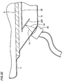
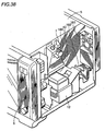
- Fig. 38 shows a variation of microwave oven 1, corresponding to Fig. 3.
- the microwave oven has a detection path member 40 having an upper portion with infrared sensor 7 attached thereto. Furthermore, detection path member 70 has a right portion with a motor 180 attached thereto to move a field of view of infrared sensor 7.
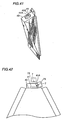
- Detection path member 40 has a top end provided with a hole 40X surrounded by a cylinder 41 provided by barring a top end of detection path member 40 in the form of a sheer cylinder on the top end surface of detection path member 40.
- cylinder 41 is formed to be partially increased in height to have a protrusion 41A.
- cylinder 41 with only protrusion 41A increased in height, can readily be formed, barred.
- infrared sensor 7 takes infrared radiation in through a detection hole 7X to detect an amount of infrared radiation.
- infrared sensor 7 when infrared sensor 7 is operated to detect an amount of infrared radiation in heating chamber 10 it has a position for example as indicated by the broken line and when it is not operated to detect infrared radiation it has a position allowing detection hole 7X facing protrusion 41A, as indicated by a solid line in Fig. 42.
- the position of infrared sensor 7 when it is not operated for detection corresponds to the position of infrared sensor 7 as shown in Fig. 38.
- protrusion 41A of cylinder 41 is located windward of any other portions of cylinder 41 as fans 181, 182 operates.
- infrared sensor 7 and its field of view is moved by sensor motor 7Z (see Fig. 9B).
- infrared sensor 7 when it is not operated for detection can have a detection component free of contaminants attributed for example to food juice scattering in heating chamber 10.
- infrared sensor 7 when infrared sensor 7 is operated for detection or when the sensor in operation for detection is shifted to stop its operation for detection the sensor moves back and forth relative to heating chamber 10. More specifically, it moves in direction Y in Figs. 14 and 15. More specifically, the present variation corresponds to a microwave oven including infrared sensor 7 having the field of view 70A moving back and forth relative to heating chamber 10, as has been described with reference to Figs. 14 and 15. It should be noted, however, that in the present variation infrared sensor 7 is only required to have a position windward of hole 40X when it is not operated for detection, and it is not limited to an application with infrared sensor 7 moving back and forth relative to heating chamber 10.
- cylinder 41 can be provided with protrusion 41A simply by barring a top end of detection path member 40 to increase cylinder 41 in height only partially, rather than entirely, to ensure a shelter for infrared sensor 7 when it is not operated for detection, and also to readily form cylinder 41. Furthermore, the shelter can be positioned not so far from the position of infrared sensor 7 when it is operated for detection.
- fans 181, 182 are attached to cool magnetron 12 and other components.
- Infrared sensor 7 when it is not operate for detection is positioned windward of cylinder 41 as fans 181, 182 operate. This ensures that infrared sensor 7 can have its detection component free of food juice scattering in heat chamber 10.
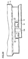
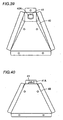
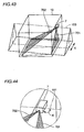
- infrared sensor 7 has a field of view moving in a manner, as will now be described with reference to Figs. 43-46.
- infrared sensor 7 is attached external to heating chamber 10 on an upper right side surface.
- infrared sensor 7 can have a field of view movable back and forth relative to heating chamber 10, i.e., (in a direction indicated in Fig. 43 by a two-head arrow Y).
- a collection of the sensor's fields of view that is provided rightmost in heating chamber 10 is shown in the form of a plane, i.e., a field of view 701, and that of the sensor's fields of view which is provided leftmost in heating chamber 10 is shown in the form of a plane, i.e., a field of view 702.
- a prism 100 is drawn to assist in describing a manner in which the field of view of infrared sensor 7 moves.
- the field of view 701 corresponds to a rightmost plane in heating chamber 10 in an area coverable by the field of view of infrared sensor 7.
- infrared sensor 7 can pivot in a direction indicated by a two-head arrow K around an axis corresponding to a line located at a topmost portion of prism 100 (a line 101 in Fig. 44) to move its field of view back and forth relative to heating chamber 10.
- the field of view 701 is a plane parallel to a side plane of the prism. In other words, the field of view 701 is perpendicular to line 101. This can minimize an area in heating chamber 10 on a side provided with infrared sensor 7 (the right side in Fig. 43) that is located on the front and rear sides and hence otherwise uncoverable by the sensor's field of view.
- infrared sensor 7 is attached to heating chamber 7 on a rearside and thus pivots rightward and leftward, infrared sensor 7 preferably pivots around an axis perpendicular to a plane corresponding to a collection of the sensor's fields of view that is provided most rearward.
- infrared sensor 7 pivots to move its field of view it pivots around an axis perpendicular to a plane within the entire region coverable by the sensor's field of view that is located in heating chamber 10 closest to the side of the heating chamber having the sensor attached thereto, as this can reduce in heating chamber 10 on a side having the sensor attached thereto an area uncoverable by the sensor's field of view.
- infrared sensor 7 can have a field of view covering heating chamber 10 over a wider area.
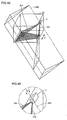
- a prism 200 is shown to assist in describing how infrared sensor 7 moves.
- infrared sensor 7 has a field of view also moving back and forth (in a direction indicated by a two-head arrow Y) as infrared sensor 7 pivots. Of areas coverable by the pivoting sensor's field of view, the rightmost and leftmost planes are shown as fields of view 703 and 704, respectively.
- infrared sensor 7 pivots around an axis corresponding to a rightmost line of prism 200 (a line 201 shown in Fig. 46). More specifically, as can be understood from Fig. 46, in this comparative example the field of view 703 and line 201 form an acute angle. As such, the field of view 703 and heating chamber 10 form a line shorter in dimension than the depth of heating chamber 10 at that portion. More specifically, when Fig. 43 is compared with Fig. 45, infrared sensor 7 can have a field of view covering in a much larger corner area closer to a side of heating chamber 10 having infrared sensor 7 attached thereto (i.e., the right side of the heating chamber 10) in Fig. 43 than in Fig. 45.
- infrared sensor pivots to move its field of view the sensor preferably pivots around an axis perpendicular to a plane within the entire region coverable by the sensor's field of view that is located in heating chamber 10 closest to a side of the heating chamber having the sensor attached thereto.
- the present variation mainly describes that in the microwave oven during a heat-cooking process infrared sensor 7 is employed to detect the temperature of a food in heating chamber 10 to automatically determine a timing at which the heating operation is terminated, as controlled in a manner as described hereinafter.
- sensor motor 7Z (shown in Fig. 9B) can move the sensor 7 field of view in the direction of the width of heating chamber 10 (direction X in Fig. 10) and the direction of the depth of heating chamber 10 (direction Y in Fig. 10).
- control determines whether the microwave oven has received an input via a key. If so then the control goes to S102.
- the control determines whether at S101 the microwave oven has received the input via a key instructing the microwave oven to provide a cooking and automatically detecting the end of the cooking (an automatic-cooking key). If so then the control goes to S103 and if not then the control provides a process corresponding to the key of interest.
- control determines whether the automatic-cooking key detected at S102 selects a course using infrared sensor 7 to detect the temperature of a food in heating chamber 10. If so then the control goes to S104 and if not then the control provides a process corresponding to the course of interest.
- control determines whether a key starting a heat-cooking operation (a start key) has been operated. If so then the control goes to S105.
- control resets contents recorded in memory about automatic-cooking and a flag and then goes to S107.
- Food sense temperature M0 is a target temperature for a heating operation. More specifically, when infrared sensor 7 senses the temperature the control terminates the current heating operation.
- control turns on a lamp illuminating heating chamber 10 and starts rotation of rotative antenna 15 and then goes to S109.
- a S110 the control controls infrared sensor 7 to start temperature detection and then goes to S111.
- control controls infrared sensor 7 to move its field of view in heating chamber 10 back and forth to scan more than one location to detect a highest temperature and then goes to S112.
- the S111 step will now be described more specifically with reference to Fig. 10.
- infrared sensor 7 has a field of view moving in heating chamber 10 back and forth relative thereto (or in direction Y in Fig. 10) and rightward and leftward (or in direction X in Fig. 10).
- a field of view is represented in an X-Y coordinate system as p(X, Y)
- infrared sensor 7 senses temperature.
- a largest variation in temperature detected in heating chamber 10 in the direction of the depth thereof, is stored in memory.
- Temperature is detected in heating chamber 10 along a plurality of lines extending in direction Y and for each line there is calculated a difference between the largest and smallest value in temperature. The largest value of such differences correspond to the largest variation in temperature in the direction of the depth of the chamber.
- the control determines whether the largest variation MX stored at S111 is at least a predetermined temperature LX. If so then the control goes to S113 and if not then the control returns to S111 and again extracts largest variation MX.
- control determines whether ten seconds have elapsed since the latest temperature detection provided by infrared sensor 7 and if so then the control goes to S114.
- control determines whether a flag F0 is reset. If so then the control goes to S115 and if it is set then the control goes to S121.
- infrared sensor 7 has its field of view moving at a rate lower than at S111. More specifically, the rate at which the field of view moves at S115 can be one fourth that at which the field of view moves at S111. More specifically in the present variation infrared sensor 7 has its field of view moving throughout heating chamber 10 at a relatively high speed to locate a food (S111-S112) and once it generally determines a line on which the food exists it detects the temperature of the food precisely (S115). Then temperature detection is provided on the line of interest to locate the food on the line of interest (S116 to S119).
- control stores in memory a temperature elevation MY subjected to the S115 temperature detection on a line at a point having attained a highest temperature value and then goes to S117.
- the control determines whether MY stored at S116 is equal to or exceeds a predetermined temperature LY. If so then the control goes to S 118 and, having made a decision that a food exists at a location subjected to the latest S116 MY detection, detects temperature with infrared sensor 7 having its field of view move in the direction of the depth including the location of interest and then goes to S119.
- the rate at which the field of view moves at S118 is equal to that at which the field of view moves at S115.
- control controls infrared sensor 7 to move the field of view in a line in the direction of the depth, as predetermined, subjected to the S118 temperature detection, to detect temperature, and the control stores a variation MZ in temperature at a location on the line of interest having a highest temperature value detected and then goes to S122. Note that the rate at which the field of view moves at S121 is equal to that at which the field of view moves at S115.
- control determines whether MZ stored at S121 is equal to or exceeds a predetermined temperature LZ. If so then the control goes to S123 and if not then the control goes to S120.
- control determines whether five seconds have elapsed since the immediate previous temperature detection performed with a field of view moving in a line and if so then the control goes to S114.
- control controls infrared sensor 7 to have a field of view fixed at a location having MZ stored at S121 and continue to detect temperature and then the control goes to S124.
- control determines whether temperature M1 detected at the immediately previously executed S125 has attained M0 set at S127. If not then the control goes back to S124 and if so then the control moves to S126.
- the control provides a setting to terminate a heating operation and then goes to S127.
- the control stops the heating operation provided by magnetron 12, turns off the lamp illuminating heating chamber 10 and stops the rotation of rotative antenna 15 and the control then goes to S128.
- the control controls a buzzer or the like to notify the user that the current heating operation ends. Then the microwave oven is placed in a waiting state.
- infrared sensor 7 includes eight infrared detection elements. At a time point these eight infrared detection elements have their respective fields of view 71A-78A projected on a bottom plane of heating chamber 10. Since the fields of view 71A-78A together cover substantially the entire area of heating chamber 10 widthwise, heating chamber 10 has any area thereof widthwise covered by the field of view of an infrared detection element.
- infrared sensor 7 is driven by sensor motor 7Z (see Fig. 9B) to pivot in a predetermined manner to move the fields of view 71A-78A back and forth relative to heating chamber 10 to provide fields of view 71B-78B and 71C-78C, respectively.
- heating chamber 10 has any area thereof covered by the field of view of an infrared detection element.
- each infrared detection element moves keeping a fixed distance as measured from the bottom plane of heating chamber 10 covered by the field of view of the infrared detection element.
- an infrared detection element has a field of view covering a uniform area.
- the fields of view 71A-71C each cover an area of the same size and so do the fields of view 72A-72C and 78A-78C. Since each field of view thus moves, each infrared detection element can have a field of view covering a constant area of heating chamber 10.
- each infrared detection element can detect temperature with constant precision, since the amount of infrared radiation that the infrared detection element can detect depends on the size of the area covered by the field of view of the infrared detection element.
- infrared sensor 7 includes five infrared detection elements 701-705. Also drawn in Figs. 50 and 51 are centerlines 701A-705A each representing the center of the field of view of a respective one of infrared detection elements 701-705.
- infrared detection elements 701-705 have their respective fields of view passing through hole 40X provided in detection path member 40 and thus reaching heating chamber 10. Infrared detection elements 701-705 are arranged to allow their respective fields of view to have their respective centerlines 701A-705A traversing each other in hole 40X at a point Q. As such, hole 40X can be minimized in diameter.
- Hole 40X reduced in diameter can further prevent food juice and the like scattering in heating chamber 10 from reaching infrared detection elements 701-705.
- infrared sensor 7 may have infrared detection elements 701-705 arranged in a line, as shown in Fig. 52, or it may have a plurality of infrared detection elements 7A on an internal wall surface of a sphere two-dimensionally, as shown in Fig. 53.
- the plurality of infrared detection elements 7A and 701-705 have their respective fields of view having their respective centers traversing each other in hole 40X before extending into heating chamber 10.
- heating chamber 10 is entirely covered by the fields of view of infrared detection elements 7A at one time such that any area of the chamber is covered by the field of view of an infrared detection element 7A.
- infrared sensor 7 includes infrared detection elements 701-705 described with reference to Fig. 50 plus an infrared detection element 706. While infrared detection elements 701-705 have their respective fields of view all directed through hole 40X to heating chamber 10, infrared detection element 706 has a field of view half blocked by a detection path member 40 and thus failing to enter heating chamber 10.
- infrared detection element 706 has a field if view 706X detecting a food then the control determines that the food's temperature cannot be detected accurately and the control stops the current heating operation, as will now be described more specifically with reference to Fig. 55.
- control initially controls magnetron 12 to start a heating operation and then at S201 drives sensor motor 7Z (see Fig. 9B) to allow any area of heating chamber 10 to be covered by the field of view of an infrared detection element.
- the infrared detection elements have their fields of view scanning throughout heating chamber 10 for temperature detection.
- control determines whether a food has been located in heating chamber 10. This decision is made based for example on whether there has been detected an area heated as time elapses. If such an area has been detected the control determines that the area includes the food and the control goes to S203.
- the control determines whether the food is located by an end of the field of view of infrared sensor 7.
- the field of view of infrared sensor 7 corresponds to a collection of the fields of view of infrared detection elements 701-706 and the end of the field of view of infrared sensor 7 corresponds to the field of view 706X, the field of view of infrared detection element 706 that is introduced into heating chamber 10. That the field of view 706 covers a food means that the food is only partially covered by the field of view of infrared sensor 7. More specifically, if infrared sensor 7 has a total field of view 700 in heating chamber 10, as shown in Fig. 56, a food R exists in heating chamber 10, only partially covered by the total field of view 700.
- infrared sensor 7 (or infrared detection elements 700-706) can hardly sense the temperature of food R accurately. As such, if at S203 the control determines that the food is located by an end of the field of view of infrared sensor 7 then it goes to S206 and at that time point controls magnetron 12 to stop the current heating operation to terminate the current process.
- control determines that the food is located by an end of the field of view of infrared sensor 7 then at S204 the control continues to detect the temperature of the food and if the food has attained a set, finish temperature corresponding to a temperature at which a heating operation should be terminated the control (S205) stops the current heating operation and ends the current process.
- infrared sensor 7 including a single infrared detection element and that including a plurality of infrared detection elements.
- infrared sensor 7 should move at least in a direction in which a shorter side of the rectangle extends. For example, if infrared sensor 7 includes infrared detection elements 7A arranged in a line, as shown in Fig. 57, or in multiple lines, as shown in Figs. 58 and 59, infrared sensor 7 should move in a direction indicated by a two-head arrow N.
- Moving infrared sensor 7 in direction N can provide a maximal variation of an area further covered by a field of view of infrared detection element 7a, relative to the distance in which each infrared sensor 7 moves. In other words, temperature can be detected throughout heating chamber 10 more rapidly.
Landscapes
- Physics & Mathematics (AREA)
- Electromagnetism (AREA)
- Engineering & Computer Science (AREA)
- Chemical & Material Sciences (AREA)
- Combustion & Propulsion (AREA)
- Mechanical Engineering (AREA)
- General Engineering & Computer Science (AREA)
- Electric Ovens (AREA)
- Control Of High-Frequency Heating Circuits (AREA)
- Radiation Pyrometers (AREA)
Applications Claiming Priority (4)
| Application Number | Priority Date | Filing Date | Title |
|---|---|---|---|
| JP2000130912 | 2000-04-28 | ||
| JP2000130912 | 2000-04-28 | ||
| JP2001022418 | 2001-01-30 | ||
| JP2001022418A JP2002013743A (ja) | 2000-04-28 | 2001-01-30 | 電子レンジ |
Publications (3)
| Publication Number | Publication Date |
|---|---|
| EP1150549A2 EP1150549A2 (en) | 2001-10-31 |
| EP1150549A3 EP1150549A3 (en) | 2005-10-19 |
| EP1150549B1 true EP1150549B1 (en) | 2007-08-01 |
Family
ID=26591246
Family Applications (1)
| Application Number | Title | Priority Date | Filing Date |
|---|---|---|---|
| EP01109953A Expired - Lifetime EP1150549B1 (en) | 2000-04-28 | 2001-04-24 | Microwave oven with infrared detection element |
Country Status (5)
| Country | Link |
|---|---|
| US (1) | US6630655B2 (enExample) |
| EP (1) | EP1150549B1 (enExample) |
| JP (1) | JP2002013743A (enExample) |
| KR (1) | KR100474777B1 (enExample) |
| CN (1) | CN1159547C (enExample) |
Families Citing this family (56)
| Publication number | Priority date | Publication date | Assignee | Title |
|---|---|---|---|---|
| JP4636702B2 (ja) * | 2001-01-30 | 2011-02-23 | 三洋電機株式会社 | 電子レンジ |
| JP2003294241A (ja) * | 2002-04-01 | 2003-10-15 | Matsushita Electric Ind Co Ltd | 加熱調理器 |
| JP2004045330A (ja) * | 2002-07-15 | 2004-02-12 | Ricoh Co Ltd | 非接触温度検知装置 |
| CN100466871C (zh) * | 2003-06-30 | 2009-03-04 | 乐金电子(天津)电器有限公司 | 微波炉检测电路 |
| CN100414273C (zh) * | 2004-04-08 | 2008-08-27 | 电子科技大学 | 一种微波炉炉腔内场分布的测试方法 |
| JP2005351566A (ja) * | 2004-06-11 | 2005-12-22 | Toshiba Corp | 加熱調理器 |
| JP4735276B2 (ja) * | 2006-01-17 | 2011-07-27 | パナソニック株式会社 | 高周波加熱装置 |
| JP4793002B2 (ja) * | 2006-02-07 | 2011-10-12 | パナソニック株式会社 | 誘導加熱装置 |
| ATE432446T1 (de) | 2006-11-02 | 2009-06-15 | Electrolux Home Prod Corp | Vorrichtung und verfahren zum bestimmen der temperatur im inneren eines garguts |
| EP1937034A1 (en) * | 2006-12-21 | 2008-06-25 | Biotage AB | Microwave heating device |
| US8610038B2 (en) * | 2008-06-30 | 2013-12-17 | The Invention Science Fund I, Llc | Microwave oven |
| US8927913B2 (en) * | 2008-06-30 | 2015-01-06 | The Invention Science Fund I, Llc | Microwave processing systems and methods |
| US20090321428A1 (en) * | 2008-06-30 | 2009-12-31 | Hyde Roderick A | Microwave oven |
| US20090321429A1 (en) * | 2008-06-30 | 2009-12-31 | Hyde Roderick A | Microwave oven |
| US20100008396A1 (en) * | 2008-07-14 | 2010-01-14 | David Gaskins | Method For Determining Internal Temperature of Meat Products |
| CN101750169B (zh) * | 2008-12-04 | 2013-09-11 | 乐金电子(天津)电器有限公司 | 微波炉中解冻物体的测量方法 |
| CN102003996A (zh) * | 2009-08-29 | 2011-04-06 | 乐金电子(天津)电器有限公司 | 鉴别微波炉上食物的形状、大小、摆放位置及温度的方法 |
| JP2011127827A (ja) * | 2009-12-17 | 2011-06-30 | Panasonic Corp | 高周波加熱装置 |
| EP2451246B1 (en) * | 2010-11-05 | 2017-01-04 | Samsung Electronics Co., Ltd. | Heating cooker with an infrared ray detection device and method of measuring the temperature of a cooking chamber of the heating cooker |
| US20120111204A1 (en) * | 2010-11-05 | 2012-05-10 | Samsung Electronics Co., Ltd. | Heating cooker |
| JP2012132624A (ja) * | 2010-12-22 | 2012-07-12 | Panasonic Corp | 加熱調理器 |
| EP2618634A1 (en) * | 2012-01-23 | 2013-07-24 | Whirlpool Corporation | Microwave heating apparatus |
| US10359318B2 (en) * | 2012-12-20 | 2019-07-23 | Raytheon Company | Radio frequency stimulated blackbody with vacuum and cryogenic capability |
| EP2773163A1 (en) * | 2013-03-01 | 2014-09-03 | Lekué, SL | Microwave oven and method to control automatically the heating and/or cooking of food in said microwave oven |
| JP6088328B2 (ja) * | 2013-04-04 | 2017-03-01 | 東芝ホームテクノ株式会社 | 加熱調理器 |
| US9668602B2 (en) | 2013-09-09 | 2017-06-06 | Whirlpool Corporation | Cooking appliance |
| JP6446672B2 (ja) * | 2014-03-18 | 2019-01-09 | パナソニックIpマネジメント株式会社 | 加熱調理器 |
| JP6292475B2 (ja) * | 2014-03-18 | 2018-03-14 | パナソニックIpマネジメント株式会社 | 高周波加熱装置 |
| GB201407939D0 (en) * | 2014-05-06 | 2014-06-18 | Mm Microwave Ltd | Heating and/or cooking apparatus |
| JP6461656B2 (ja) * | 2015-03-16 | 2019-01-30 | 日立アプライアンス株式会社 | 加熱調理器 |
| WO2016170734A1 (ja) * | 2015-04-24 | 2016-10-27 | パナソニックIpマネジメント株式会社 | 加熱調理器 |
| US10739013B2 (en) | 2015-05-05 | 2020-08-11 | June Life, Inc. | Tailored food preparation with an oven |
| EP3292738B1 (en) | 2015-05-05 | 2020-12-30 | June Life, Inc. | A connected oven |
| US11324083B1 (en) * | 2015-09-06 | 2022-05-03 | Muhammad Shahir Rahman | Apparatus for intelligent and selective heating using sensor array |
| WO2017077695A1 (ja) * | 2015-11-05 | 2017-05-11 | パナソニックIpマネジメント株式会社 | 加熱調理器 |
| DE102016215549A1 (de) * | 2016-08-18 | 2018-02-22 | Bayerische Motoren Werke Aktiengesellschaft | Elektrische Heizeinrichtung für Kraftfahrzeuge |
| KR102556536B1 (ko) * | 2016-09-30 | 2023-07-17 | 삼성전자주식회사 | 조리 기기 및 조리 기기의 제어 방법 |
| US10383183B2 (en) * | 2016-12-05 | 2019-08-13 | Hall Labs Llc | Microwave oven with oscillating magnetron |
| US11191370B2 (en) | 2017-08-24 | 2021-12-07 | Unified Brands, Inc. | Temperature monitoring and control system |
| US11666160B2 (en) | 2017-08-24 | 2023-06-06 | Unified Brands, Inc. | Method for temperature monitoring and regulation and systems therefor |
| CN107595152B (zh) * | 2017-09-28 | 2020-11-27 | 上海纯米电子科技有限公司 | 烤箱分区温控方法 |
| US11116050B1 (en) | 2018-02-08 | 2021-09-07 | June Life, Inc. | High heat in-situ camera systems and operation methods |
| US11422037B2 (en) * | 2018-03-15 | 2022-08-23 | Brava Home, Inc. | Temperature probe systems and methods |
| JP7217421B2 (ja) * | 2018-04-19 | 2023-02-03 | パナソニックIpマネジメント株式会社 | 加熱調理器 |
| CN109164322A (zh) * | 2018-09-21 | 2019-01-08 | 国网辽宁省电力有限公司铁岭供电公司 | 干式配电变压器绕组线圈材质判定方法及分析装置 |
| TWI699166B (zh) * | 2019-01-02 | 2020-07-21 | 愛利奧有限公司 | 豆體溫度探測元件及其測溫方法 |
| US11927488B2 (en) * | 2019-01-03 | 2024-03-12 | Chia-Ling Chen | Thermal detection system capable of providing early warning and related products |
| TWM589767U (zh) * | 2019-09-26 | 2020-01-21 | 統一超商股份有限公司 | 商用微波爐 |
| CN110693342B (zh) * | 2019-09-30 | 2021-01-01 | 广东美的厨房电器制造有限公司 | 烤箱的控制方法及具有其的烤箱 |
| WO2021102254A1 (en) | 2019-11-20 | 2021-05-27 | June Life, Inc. | System and method for estimating foodstuff completion time |
| US11680712B2 (en) | 2020-03-13 | 2023-06-20 | June Life, Inc. | Method and system for sensor maintenance |
| US11593717B2 (en) | 2020-03-27 | 2023-02-28 | June Life, Inc. | System and method for classification of ambiguous objects |
| WO2022036321A1 (en) | 2020-08-14 | 2022-02-17 | June Life, Inc. | System and method for targeted heating element control |
| KR102707142B1 (ko) * | 2021-07-20 | 2024-09-19 | 아놀드 체이스 | 지능형 마이크로파 조리 시스템 |
| JP2023131515A (ja) * | 2022-03-09 | 2023-09-22 | 日立グローバルライフソリューションズ株式会社 | 加熱調理器、加熱調理器の制御方法、および、制御プログラム |
| CN119404057A (zh) * | 2022-09-15 | 2025-02-07 | 三星电子株式会社 | 用于通过使用烤架加热器烹饪食物材料的烹饪设备 |
Family Cites Families (11)
| Publication number | Priority date | Publication date | Assignee | Title |
|---|---|---|---|---|
| JPS62165893A (ja) | 1986-01-17 | 1987-07-22 | 株式会社東芝 | 加熱調理器 |
| JP3067167B2 (ja) | 1990-07-05 | 2000-07-17 | キヤノン株式会社 | 画像読取装置 |
| JPH06201137A (ja) * | 1992-12-28 | 1994-07-19 | Matsushita Electric Ind Co Ltd | 調理器具 |
| AU695236B2 (en) * | 1994-10-20 | 1998-08-13 | Matsushita Electric Industrial Co., Ltd. | High-frequency heating device |
| JP2723057B2 (ja) * | 1994-11-17 | 1998-03-09 | 松下電器産業株式会社 | 加熱調理器 |
| JPH0961245A (ja) * | 1995-08-29 | 1997-03-07 | Matsushita Electric Ind Co Ltd | 非接触温度計 |
| SE505555C2 (sv) * | 1995-12-21 | 1997-09-15 | Whirlpool Europ | Förfarande för styrning av ett uppvärmningsförlopp i en mikrovågsugn samt mikrovågsugn |
| JP3128524B2 (ja) * | 1997-01-31 | 2001-01-29 | 三洋電機株式会社 | 電子レンジ |
| CA2229951C (en) * | 1997-03-18 | 2002-05-07 | Sanyo Electric Co., Ltd. | Cooking apparatus including infrared ray sensor |
| JP2000130766A (ja) | 1998-10-28 | 2000-05-12 | Toshiba Corp | オーブンレンジ |
| US6132084A (en) * | 1998-11-30 | 2000-10-17 | General Electric Company | Infrared non-contact temperature measurement for household appliances |
-
2001
- 2001-01-30 JP JP2001022418A patent/JP2002013743A/ja active Pending
- 2001-04-13 KR KR10-2001-0019959A patent/KR100474777B1/ko not_active Expired - Fee Related
- 2001-04-16 CN CNB011105925A patent/CN1159547C/zh not_active Expired - Fee Related
- 2001-04-24 EP EP01109953A patent/EP1150549B1/en not_active Expired - Lifetime
- 2001-04-26 US US09/842,239 patent/US6630655B2/en not_active Expired - Fee Related
Also Published As
| Publication number | Publication date |
|---|---|
| CN1321854A (zh) | 2001-11-14 |
| US6630655B2 (en) | 2003-10-07 |
| US20020005406A1 (en) | 2002-01-17 |
| EP1150549A3 (en) | 2005-10-19 |
| EP1150549A2 (en) | 2001-10-31 |
| KR100474777B1 (ko) | 2005-03-08 |
| JP2002013743A (ja) | 2002-01-18 |
| KR20010104621A (ko) | 2001-11-26 |
| CN1159547C (zh) | 2004-07-28 |
Similar Documents
| Publication | Publication Date | Title |
|---|---|---|
| EP1150549B1 (en) | Microwave oven with infrared detection element | |
| US6563097B2 (en) | Microwave oven with food search and localized heating | |
| US6590192B2 (en) | Microwave oven with temperature-dependent automatic stop | |
| JP4979280B2 (ja) | マイクロ波加熱装置 | |
| EP2348257B1 (en) | Microwave cooking device | |
| JP3669030B2 (ja) | 高周波加熱装置 | |
| JP5076625B2 (ja) | マイクロ波加熱装置 | |
| JP5076626B2 (ja) | マイクロ波加熱装置 | |
| KR100485510B1 (ko) | 전기가열 조리기 | |
| JP4636702B2 (ja) | 電子レンジ | |
| JP2002168457A (ja) | 電子レンジ | |
| JP5076627B2 (ja) | マイクロ波加熱装置 | |
| JP2005283117A (ja) | 電子レンジ | |
| JP4924197B2 (ja) | マイクロ波加熱装置およびプログラム | |
| JP5003273B2 (ja) | マイクロ波加熱装置 | |
| JP2003287232A (ja) | 加熱調理器 | |
| JP2853610B2 (ja) | 高周波加熱装置 | |
| JPH09306664A (ja) | 高周波加熱装置 | |
| JP4967796B2 (ja) | マイクロ波加熱装置 | |
| JP5194561B2 (ja) | マイクロ波加熱装置 | |
| JP5076631B2 (ja) | マイクロ波加熱装置およびプログラム | |
| JPH07318075A (ja) | 加熱調理器 | |
| JP2002317938A (ja) | 電子レンジ | |
| JP2011086486A (ja) | マイクロ波加熱装置 | |
| JP2000123967A (ja) | 電子レンジ |
Legal Events
| Date | Code | Title | Description |
|---|---|---|---|
| PUAI | Public reference made under article 153(3) epc to a published international application that has entered the european phase |
Free format text: ORIGINAL CODE: 0009012 |
|
| AK | Designated contracting states |
Kind code of ref document: A2 Designated state(s): AT BE CH CY DE DK ES FI FR GB GR IE IT LI LU MC NL PT SE TR |
|
| AX | Request for extension of the european patent |
Free format text: AL;LT;LV;MK;RO;SI |
|
| PUAL | Search report despatched |
Free format text: ORIGINAL CODE: 0009013 |
|
| AK | Designated contracting states |
Kind code of ref document: A3 Designated state(s): AT BE CH CY DE DK ES FI FR GB GR IE IT LI LU MC NL PT SE TR |
|
| AX | Request for extension of the european patent |
Extension state: AL LT LV MK RO SI |
|
| RIC1 | Information provided on ipc code assigned before grant |
Ipc: 7H 05B 6/68 B Ipc: 7H 05B 6/80 A |
|
| 17P | Request for examination filed |
Effective date: 20060302 |
|
| AKX | Designation fees paid |
Designated state(s): GB |
|
| REG | Reference to a national code |
Ref country code: DE Ref legal event code: 8566 |
|
| 17Q | First examination report despatched |
Effective date: 20060905 |
|
| GRAP | Despatch of communication of intention to grant a patent |
Free format text: ORIGINAL CODE: EPIDOSNIGR1 |
|
| RIN1 | Information on inventor provided before grant (corrected) |
Inventor name: MUKUMOTO, EIJIC/O SANYO ELECTRIC CO., LTD., Inventor name: TANAKA, MASAHIROC/O SANYO ELECTRIC CO., LTD., Inventor name: KUME, KENJIC/O SANYO ELECTRIC CO., LTD., Inventor name: TAINO, KAZUOC/O SANYO ELECTRIC CO., LTD., Inventor name: NODA, MASARUC/O SANYO ELECTRIC CO., LTD., Inventor name: FUKUNAGA, EIJIC/O SANYO ELECTRIC CO., LTD., |
|
| GRAS | Grant fee paid |
Free format text: ORIGINAL CODE: EPIDOSNIGR3 |
|
| GRAA | (expected) grant |
Free format text: ORIGINAL CODE: 0009210 |
|
| AK | Designated contracting states |
Kind code of ref document: B1 Designated state(s): GB |
|
| REG | Reference to a national code |
Ref country code: GB Ref legal event code: FG4D |
|
| PLBE | No opposition filed within time limit |
Free format text: ORIGINAL CODE: 0009261 |
|
| STAA | Information on the status of an ep patent application or granted ep patent |
Free format text: STATUS: NO OPPOSITION FILED WITHIN TIME LIMIT |
|
| 26N | No opposition filed |
Effective date: 20080506 |
|
| PGFP | Annual fee paid to national office [announced via postgrant information from national office to epo] |
Ref country code: GB Payment date: 20080430 Year of fee payment: 8 |
|
| GBPC | Gb: european patent ceased through non-payment of renewal fee |
Effective date: 20090424 |
|
| PG25 | Lapsed in a contracting state [announced via postgrant information from national office to epo] |
Ref country code: GB Free format text: LAPSE BECAUSE OF NON-PAYMENT OF DUE FEES Effective date: 20090424 |