EP1150180B1 - Induktionsbeheizte Fixiervorrichtung für ein Bilderzeugungsgerät, sowie Induktionsheizspule hierfür - Google Patents
Induktionsbeheizte Fixiervorrichtung für ein Bilderzeugungsgerät, sowie Induktionsheizspule hierfür Download PDFInfo
- Publication number
- EP1150180B1 EP1150180B1 EP01110087A EP01110087A EP1150180B1 EP 1150180 B1 EP1150180 B1 EP 1150180B1 EP 01110087 A EP01110087 A EP 01110087A EP 01110087 A EP01110087 A EP 01110087A EP 1150180 B1 EP1150180 B1 EP 1150180B1
- Authority
- EP
- European Patent Office
- Prior art keywords
- coil
- induction heating
- coils
- bobbin
- fixing device
- Prior art date
- Legal status (The legal status is an assumption and is not a legal conclusion. Google has not performed a legal analysis and makes no representation as to the accuracy of the status listed.)
- Expired - Lifetime
Links
- 238000010438 heat treatment Methods 0.000 title claims description 88
- 230000006698 induction Effects 0.000 title claims description 79
- 239000004020 conductor Substances 0.000 claims description 37
- 230000004907 flux Effects 0.000 claims description 6
- 239000003779 heat-resistant material Substances 0.000 claims description 4
- 230000004048 modification Effects 0.000 description 26
- 238000012986 modification Methods 0.000 description 26
- 238000000034 method Methods 0.000 description 11
- 230000001939 inductive effect Effects 0.000 description 8
- 238000012546 transfer Methods 0.000 description 8
- 238000009413 insulation Methods 0.000 description 7
- 238000004140 cleaning Methods 0.000 description 6
- 238000010276 construction Methods 0.000 description 6
- 238000004519 manufacturing process Methods 0.000 description 5
- 239000012811 non-conductive material Substances 0.000 description 5
- 238000009826 distribution Methods 0.000 description 4
- 230000002500 effect on skin Effects 0.000 description 4
- 229910052736 halogen Inorganic materials 0.000 description 4
- 150000002367 halogens Chemical class 0.000 description 4
- WABPQHHGFIMREM-UHFFFAOYSA-N lead(0) Chemical compound [Pb] WABPQHHGFIMREM-UHFFFAOYSA-N 0.000 description 4
- 239000000696 magnetic material Substances 0.000 description 4
- 238000006243 chemical reaction Methods 0.000 description 3
- 230000002950 deficient Effects 0.000 description 3
- 239000002184 metal Substances 0.000 description 3
- 229910052751 metal Inorganic materials 0.000 description 3
- 230000005855 radiation Effects 0.000 description 3
- RYGMFSIKBFXOCR-UHFFFAOYSA-N Copper Chemical compound [Cu] RYGMFSIKBFXOCR-UHFFFAOYSA-N 0.000 description 2
- XEEYBQQBJWHFJM-UHFFFAOYSA-N Iron Chemical compound [Fe] XEEYBQQBJWHFJM-UHFFFAOYSA-N 0.000 description 2
- 230000015572 biosynthetic process Effects 0.000 description 2
- 230000015556 catabolic process Effects 0.000 description 2
- 238000001816 cooling Methods 0.000 description 2
- 238000011161 development Methods 0.000 description 2
- 230000018109 developmental process Effects 0.000 description 2
- 239000012212 insulator Substances 0.000 description 2
- 230000001788 irregular Effects 0.000 description 2
- 230000009467 reduction Effects 0.000 description 2
- 239000000919 ceramic Substances 0.000 description 1
- 239000012141 concentrate Substances 0.000 description 1
- 238000007796 conventional method Methods 0.000 description 1
- 229910052802 copper Inorganic materials 0.000 description 1
- 239000010949 copper Substances 0.000 description 1
- 230000001419 dependent effect Effects 0.000 description 1
- 230000005684 electric field Effects 0.000 description 1
- 230000005674 electromagnetic induction Effects 0.000 description 1
- 238000005516 engineering process Methods 0.000 description 1
- NBVXSUQYWXRMNV-UHFFFAOYSA-N fluoromethane Chemical compound FC NBVXSUQYWXRMNV-UHFFFAOYSA-N 0.000 description 1
- 230000012447 hatching Effects 0.000 description 1
- 230000020169 heat generation Effects 0.000 description 1
- 229920006015 heat resistant resin Polymers 0.000 description 1
- 239000011810 insulating material Substances 0.000 description 1
- 229910052742 iron Inorganic materials 0.000 description 1
- 230000013011 mating Effects 0.000 description 1
- 230000001737 promoting effect Effects 0.000 description 1
- 230000008439 repair process Effects 0.000 description 1
- 229920005989 resin Polymers 0.000 description 1
- 239000011347 resin Substances 0.000 description 1
- 229910001220 stainless steel Inorganic materials 0.000 description 1
- 239000010935 stainless steel Substances 0.000 description 1
- 230000001360 synchronised effect Effects 0.000 description 1
Images








Classifications
-
- G—PHYSICS
- G03—PHOTOGRAPHY; CINEMATOGRAPHY; ANALOGOUS TECHNIQUES USING WAVES OTHER THAN OPTICAL WAVES; ELECTROGRAPHY; HOLOGRAPHY
- G03G—ELECTROGRAPHY; ELECTROPHOTOGRAPHY; MAGNETOGRAPHY
- G03G15/00—Apparatus for electrographic processes using a charge pattern
- G03G15/20—Apparatus for electrographic processes using a charge pattern for fixing, e.g. by using heat
- G03G15/2003—Apparatus for electrographic processes using a charge pattern for fixing, e.g. by using heat using heat
- G03G15/2014—Apparatus for electrographic processes using a charge pattern for fixing, e.g. by using heat using heat using contact heat
- G03G15/2053—Structural details of heat elements, e.g. structure of roller or belt, eddy current, induction heating
-
- H—ELECTRICITY
- H05—ELECTRIC TECHNIQUES NOT OTHERWISE PROVIDED FOR
- H05B—ELECTRIC HEATING; ELECTRIC LIGHT SOURCES NOT OTHERWISE PROVIDED FOR; CIRCUIT ARRANGEMENTS FOR ELECTRIC LIGHT SOURCES, IN GENERAL
- H05B6/00—Heating by electric, magnetic or electromagnetic fields
- H05B6/02—Induction heating
- H05B6/10—Induction heating apparatus, other than furnaces, for specific applications
- H05B6/14—Tools, e.g. nozzles, rollers, calenders
-
- H—ELECTRICITY
- H05—ELECTRIC TECHNIQUES NOT OTHERWISE PROVIDED FOR
- H05B—ELECTRIC HEATING; ELECTRIC LIGHT SOURCES NOT OTHERWISE PROVIDED FOR; CIRCUIT ARRANGEMENTS FOR ELECTRIC LIGHT SOURCES, IN GENERAL
- H05B6/00—Heating by electric, magnetic or electromagnetic fields
- H05B6/02—Induction heating
- H05B6/10—Induction heating apparatus, other than furnaces, for specific applications
- H05B6/14—Tools, e.g. nozzles, rollers, calenders
- H05B6/145—Heated rollers
-
- G—PHYSICS
- G03—PHOTOGRAPHY; CINEMATOGRAPHY; ANALOGOUS TECHNIQUES USING WAVES OTHER THAN OPTICAL WAVES; ELECTROGRAPHY; HOLOGRAPHY
- G03G—ELECTROGRAPHY; ELECTROPHOTOGRAPHY; MAGNETOGRAPHY
- G03G2215/00—Apparatus for electrophotographic processes
- G03G2215/20—Details of the fixing device or porcess
- G03G2215/2003—Structural features of the fixing device
- G03G2215/2016—Heating belt
-
- G—PHYSICS
- G03—PHOTOGRAPHY; CINEMATOGRAPHY; ANALOGOUS TECHNIQUES USING WAVES OTHER THAN OPTICAL WAVES; ELECTROGRAPHY; HOLOGRAPHY
- G03G—ELECTROGRAPHY; ELECTROPHOTOGRAPHY; MAGNETOGRAPHY
- G03G2215/00—Apparatus for electrophotographic processes
- G03G2215/20—Details of the fixing device or porcess
- G03G2215/2003—Structural features of the fixing device
- G03G2215/2016—Heating belt
- G03G2215/2025—Heating belt the fixing nip having a rotating belt support member opposing a pressure member
- G03G2215/2032—Heating belt the fixing nip having a rotating belt support member opposing a pressure member the belt further entrained around additional rotating belt support members
Definitions
- the present invention relates to a fixing device for a printer, facsimile apparatus, copier or similar electrophotographic image forming apparatus and more particularly to an induction heating type fixing device using electromagnetic induction. Further, the present invention relates to an induction coil for use in the induction heating type fixing device.
- an image forming apparatus includes a fixing device for fixing a toner image on a paper sheet or similar recording medium.
- a fixing device for fixing a toner image on a paper sheet or similar recording medium.
- One of conventional fixing device uses a heat roller to be heated and a press roller pressed against the heat roller The heat roller and press roller fix a toner image on a paper sheet with heat and pressure while conveying the paper sheet.
- a halogen lamp, halogen heater or similar heat source has traditionally been disposed in the heat roller for heating the heat source to a preselected temperature necessary for fixation.
- an induction heating type fixing system is attracting increasing attention because it heats a heat roller, which is formed of conductive metal, by using eddy current derived from an electromagnetic wave.
- Japanese Patent Laid-Open Publication No. 2000-133627 discloses an induction heating type fixing device capable of obviating hot offset and reducing wasteful power consumption.
- the fixing device disclosed includes a main coil and an auxiliary coil assigned to a range covering small paper sizes and a range outside of the above range, respectively.
- the main coil and auxiliary coil are wound round a single bobbin and controlled independently of each other as to current supply.
- the gap between the coils and a heat roller should preferably be as small as possible in order to efficiently heat the heat roller. To reduce the gap, the end portions of the auxiliary coil are laid inside of the bobbin.
- the auxiliary coil is positioned at opposite end portions of the bobbin while the main coil is positioned at the center of the same. This brings about a problem that the main coil is laid inside of the bobbin, making it difficult to deal with the end portions of the coils. Further, when any part of the coils snaps, all the coils must be rewound. A period of time necessary for rewinding work is so long, the coils are bodily replaced, i.e., even the coil not snapped is discarded.
- the warm-up time of the fixing device can be reduced if the thermal capacity of the heat roller is reduced.
- the wall thickness of the heat roller may be reduced, as proposed in the past. This, however, brings about another problem that substantially no heat conduction occurs in the heat roller in the axial direction because the heat roller has a core whose thermal conductivity is relatively low.
- a system in which a plurality of coils are selectively energized in accordance with sheet size. This allows only necessary part of the heat roller to be heated and thereby further saves energy.
- the plurality of coils require a number of leads to be laid between the heat roller and the coils. Therefore, to protect the coils from damage ascribable to, e.g., short-circuiting, a sufficient gap is necessary between the heat roller and the coils and leads. Such a gap increases the distance between the coils and the heat roller and thereby aggravates thermal conversion efficiency. Moreover, a number of leads increase the number of wiring steps and therefore production cost.
- JP 10 01901 A describes a fixing roller in a fixing device.
- a first inductive wound layer is installed inside, and the second inductive wound layer is installed outside of the first inductive wound layer in a core part.
- a lead wire of the first inductive wound layer is made to pass through a hollow part of a fixing shaft, and the high frequency current is supplied to the first inductive wound layer through the lead wire.
- a lead wire of the second inductive wound layer is made to pass through a hollow part of a fixing shaft, and the second high frequency current is supplied through the lead wire.
- the energization control is performed so that the current is not simultaneously supplied to the plural inductive wound layers in the fixing operation.
- a size of recording paper to be supplied is detected by a signal from a paper supplying part, and the high frequency current is supplied to the first or second inductive wound layers corresponding to the detected paper width of the recording paper, so that a cylindrical member is heated by the induced current to heat a fixing roller.
- JP 2000 066543 A describes an induction heat fixing device. Magnetic materials are moved in accordance with the temperature of the end part of a heating roller, and the magnetic flux passing the end part of the heating roller is varied. This device is controlled so that the heat of the center part of the heating roller is taken by transfer paper when transfer paper whose paper width is made small and whose size is small is successively fixed and carried and many more currents are made to flow through a coil so as to replenish it.
- the magnetic materials are moved to the center side of the coil.
- the magnetic flux of the outside of an induction heating coil is reduced by this movement, and many magnetic fluxes pass on the side of the magnetic materials at inside, so that the heat generation of the end part of the heating roller is reduced.
- the aforementioned object is solved by the subject-matter of the independent claim.
- the dependent claims are directed to advantageous embodiments.
- a low cost, induction heating type fixing device capable of promoting stable heating without lowering thermal conversion efficiency, an induction heating coil therefor, and a method of producing the coil.
- an induction heating type fixing device easy to produce and repair, an induction heating coil therefor, and a method of producing the coil.
- an image forming apparatus including the induction heating type fixing device stated above.
- an induction heating coil including a bobbin formed of a heat-resistant material and a conductor wound round the bobbin, a particular conductor is wound round each of a plurality of bobbins having different diameters and assembled in a telescopic manner.
- an induction heating type fixing device for fixing a toner image on a recording medium
- the induction heating type device includes two rollers for conveying the recording medium while nipping it, and an induction heating coil associated with at least one of the rollers for generating an induction magnetic flux.
- the induction heating coil has a plurality of bobbins formed of a heat-resistant material and each having a particular diameter. The bobbins are assembled in a telescopic manner. A plurality of conductors each are wound round one of the bobbins.
- an image forming apparatus including an induction heating type fixing device for fixing a toner image on a recording medium
- the induction heating type fixing device includes two rollers for conveying the recording medium while nipping it, and an induction heating coil associated with at least one of the two rollers for generating an induction magnetic flux.
- the induction heating coil has a plurality of bobbins formed of a heat-resistant material and each having a particular diameter. The bobbins are assembled in a telescopic manner. A plurality of conductors each are wound round one of the bobbins.
- the bobbin is implemented as a plurality of bobbin members removably connected to each other. After a particular conductor has been wound on each bobbin member, the bobbin members are assembled.
- An induction heating type fixing system is one of such fixing systems and heats a heat roller, which is formed of conductive metal, by using eddy current derived from an electromagnetic wave.
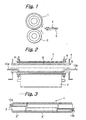
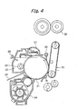
- FIG. 2 shows a specific configuration of a fixing device using the induction heating type fixing system.
- the fixing device includes a hollow heat roller 1 and a press roller 2 pressed against the heat roller 1.
- the heat roller 1 is formed of conductive metal and journalled to brackets 7 via bearings 9.
- the press roller 2 is rotatable in contact with the heat roller 1.
- a gear, not shown, is mounted on one end of the heat roller 1 and held in mesh with a drive bear not shown. When the heat roller 1 is caused to rotate by the drive gear, it causes the press roller 2 to rotate.
- the heat roller 3 includes a core formed of stainless steel, iron or similar magnetic material and a parting layer covering the core.
- the parting layer is formed of fluorocarbon resin.
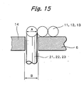
- FIG. 3 shows an induction heating type fixing device proposed in Japanese Patent Application No. 2000-133627 mentioned earlier and constructed to avoid hot offset and to reduce wasteful power consumption.
- the fixing device includes a main induction coil 3' and an auxiliary induction coil 3" that are wound round a single bobbin 6.
- the main coil 3' covers a range corresponding to small sheet sizes while the auxiliary coil 3" covers ranges outside of the above range.
- Current supply to the main coil 3' and current supply to the auxiliary coil 3" are controlled independently of each other.
- the charger 22 uniformly charges the surface of the drum 21.
- the laser beam 23 scans the charged surface of the drum 21 to thereby form a latent image on the drum 21.
- the developing device 24 deposits charged toner on the latent image to thereby produce a corresponding toner image.
- the image transferring device 25 transfers the toner image from the drum 21 to a paper sheet or similar recording medium.
- the cleaning device 27 removes the toner left on the drum 21 after the image transfer.
- the discharger 28 discharges potential left on the drum 21 for thereby preparing the drum 21 for another image formation.
- the image forming apparatus forms an image by negative-to-positive development, i.e., by causing the toner to deposit on the portions of the drum 21 where potential is low. Then, after a charge roller 22' included in the charger 22 has uniformly charged the surface of the drum 21, the laser beam 23 forms a latent image on the drum 21.
- the developing device 24 develops the latent image to thereby form a corresponding toner image.
- a fixing device 30 fixes the toner image on the paper sheet.
- the cleaning device 27 removes and collects the toner left on the drum 21 without being transferred to the paper sheet. Subsequently, the discharger 28 discharges potential left on the drum 21.
- the inner bobbin 6b with the coil 3b is inserted into the outer bobbin 6a with the coil 3a in a direction indicated by an arrow A.
- the coils 3a and 3b should only be wound round the bobbins 6a and 6b, respectively, and are therefore easy to configure. Further, when either one of the coils 3a and 3b snaps, only the snapped coil should be replaced. While the end portions of the coils 3a and 3b are shown as being laid outside of the respective bobbins 6a and 6b, the former may be laid inside of the latter.
- FIG. 7 shows an alternative configuration in which the coil 3a is wound round the inner bobbin while the coil 3b is wound round the outer bobbin.
- the outer coil is more efficient than the inner coil because the gap between the outer coil and the core of a heat roller is small. It is therefore preferable to position one coil expected to be mainly used for fixation outside of the other coil.
- width and the number of turns of each coil shown in FIGS. 5 through 7 are only illustrative and may be suitably varied in accordance with the sheet passing width and a reference position (center or end) for sheet passage available with an image forming apparatus.
- FIG. 8A shows a relation between a heat roller 1 and a paper sheet being conveyed by the heat roller 1 with the center used as-a reference.
- FIG. 8B shows a relation between the heat roller 1 and the paper sheet being conveyed with one edge used as a reference.
- part of the heat roller 1 over which the paper sheet passes in both of an A4 profile position and an A4 landscape position is a main sheet passing range, as indicated by hatching.
- part of the heat roller 1 over which the paper sheet passes in an A4 profile position, but does not pass in an A4 landscape position,- is an auxiliary sheet passing range or ranges, as indicated by dots.
- FIG. 9 shows a specific configuration of the induction heating coil applicable to the case wherein the paper sheet is passed with the center used as a reference.
- the coil is made up of coils or conductors 3b and 3c wound round the outer bobbin 6a and inner bobbin 6b, respectively.
- the coils 3b and 3c respectively cover the main range and auxiliary ranges of the heat roller shown in FIG. 8A .
- the coils 3b and 3c are controlled independently of each other as in the conventional configuration. Specifically, to deal with the maximum sheet size, current is fed to both of the coils 3b and 3c while, to deal with smaller sheet sizes, current is fed only to the coil 3b.
- the coils 3b and 3c are easy to assemble. Moreover, when either one of the coils 3b and 3c snaps, only the snapped coil should be replaced.
- the coil 3b at the center should preferably have a width of 210 mm to 270 mm, which is equal to or greater than the A4 profile size of 210 mm by up to 60 mm.
- Such a width of the coil 3b is selected in consideration of heat radiation at opposite ends. With this configuration, it is possible to efficiently fix an image carried on a paper sheet without regard to the sheet width.
- FIG. 10 shows a specific configuration of the induction heating coil applicable to the case wherein the paper sheet is passed with one edge used as a reference.
- the coil is made up of a main coil 3d and an auxiliary coils 3e wound round the outer bobbin 6a and inner bobbin 6b, respectively.
- the main coil 3d and auxiliary coil 3e respectively cover the main range and auxiliary range shown in FIG. 8B .
- the main coil 3d and auxiliary coil 3e are also controlled independently of each other as in the-conventional-configuration. Specifically, to deal with the maximum sheet size, current is fed to both of the coils 3d and 3e while, to deal with smaller sheet sizes, current is fed only to the coil 3d.
- the main coil 3d should preferably have a width of 210 mm to 270 mm in consideration of heat radiation at opposite edges.
- the gap between the coil wound round the inner bobbin 6b and the core of the heat roller is greater than the gap between the coil wound round the outer bobbin 6a and the core, lowering the heating efficiency.
- a spiral groove is formed in each of the bobbins 6a and 6b. The coils each are wound along a particular spiral groove. This successfully brings both of the coils closer to the heat roller and therefore enhances heating efficiency accordingly.
- FIGS. 12A and 12B respectively show the coil 3 wound round the bobbin 6 with the spiral groove and the coil 3 wound round the bobbin 6 without the spiral groove.
- the coil 3 on the bobbin 6 with the spiral groove has a height h smaller than the height h' of the coil 3 on the bobbin 6 without the spiral groove and is therefore closer to the core of the heat roller.
- the spiral groove may be assigned to only part of the coil 3.
- the inner bobbin in particular, may not be formed with the spiral groove in order to bring the associated coil further closer to the core of the heat roller.
- the illustrative embodiment has a plurality of bobbins assembled in a telescopic manner, facilitating the production of the individual coil. Even when one coil snaps, only the snapped coil should be replaced.
- the coil wound round the outer bobbin is closer to the core of the heat roller than the coil wound round the inner bobbin.
- the coil on the outer bobbin as a main coil, it is possible to enhance the efficient operation of the fixing device.
- assigning one coil to the main sheet passing range and assigning the other coil to the auxiliary sheet passing range it is possible to efficiently fix a toner image without regard to the sheet size.
- the spiral groove formed in the bobbin reduces the height of the coil received therein and therefore the gap between the coil and the heat roller. This desirably enhances heating efficiency.
- the heat roller 1 includes a main coil 11 and two auxiliary coils 12 and 13.
- the main coil 11 and auxiliary coils 12 and 13 respectively have right leads 21R, 22R and 23R and left leads 21L, 22L and 23L.
- the right and left leads 21R and 21L of the main coil 11 are connected to a coil drive circuit, not shown, by being laid inside of the auxiliary coils 13 and 12, respectively.
- the left lead 22L of the auxiliary coil 12 and the right lead 23R of the auxiliary coil 13, which are positioned at opposite ends, are directly connected to the coil drive circuit.
- the right lead 22R of the auxiliary coil 12 and the left lead 23L of the auxiliary coil 13 are interconnected at the inside of the main coil 11.
- the leads 21R, 21L, 22R and 23L may be protected from breakdown by an organic insulator implemented as a tube or a tape for a safety purpose.
- the bobbin 6 is formed with round holes 14 (only one is shown) for passing the leads 21R and 21L of the main coil 11 and the leads 22R and 23L of the auxiliary coils 12 and 13, respectively.
- the holes 14 each are positioned at the beginning or the end of a particular coil. Assuming that all the leads 21L, 21R, 22R and 23L have a diameter A, then the holes 14 have a diameter B greater than the diameter A.
- the leads 21R, 21L, 22R and 23L are laid inside of the bobbin 6. Therefore, a space that insures insulation without lowering heating efficiency can be secured, as in the illustrative example. Also, the space inside of the coils is effectively-used to make the-entire fixing device compact. Further, the coils 11 through 13 are wound round the bobbin 6 formed of a nonconductive material. The nonconductive material intervening between the leads 21R, 21L, 22R and 23L and the coils protects the coils or an inverter circuit from damage ascribable to, e.g., short-circuiting. Moreover, the round holes 14 formed in the bobbin 14 allow the coils 11 through 13 to be accurately positioned. In addition, the holes 14 greater in diameter than the leads facilitate wiring work and reduce the production cost of the induction heating coil.
- FIGS. 16A and 16B show another modification of the illustrative example.
- the coils 11 through 13 are again wound round the hollow cylindrical bobbin 6 formed of a nonconductive material.
- the leads 21R and 21R of the main coil 11 and the leads 22R and 23L of the auxiliary coils 12 and 13, respectively, are connected to the coil drive circuit by being laid in channels 15 formed in the bobbin 6.
- the channels 15 have a depth D and a width W greater than the diameter A of the leads 21 through 23, and each extends from the end of the associated coil to the end of the bobbin 6.
- the leads 21R, 21L, 22R and 23L each are laid in a particular groove 15 formed in the bobbin 6. Therefore, a space that insures insulation without lowering heating efficiency can be secured, as in the illustrative example. Also, the space inside of the coils is effectively used to make the entire heating device compact.
- FIG. 23 shows the fixing device applicable to an image forming apparatus of the type feeding a paper sheet by using one edge as a reference.
- the fixing device includes the main coil 11 having a width equal to or slightly greater than the width A4T and the auxiliary coil 12 contiguous with the main coil 11.
- the auxiliary coil 12 has a width covering the width A4Y when combined with the width of the main coil 11.
- the two coils 11 and 12 are wound round the bobbin 6 whose axis is substantially coincident with the axis of the heat roller 1.
- the ends of the coils 11 and 12 are connected to a control circuit not shown.
- FIG. 25A the bobbin 6 is formed with holes 14a, 14b, 14c and 14d at opposite end portions and portions between the main coil 11 and the auxiliary coil 12.
- FIG. 25B the main coil 11 is wound round the bobbin 6 with its right lead 21R and left lead 21L connected to the coil drive circuit via the holes 14c and 14a, respectively.
- the auxiliary coil 12 is wound round the bobbin 6 with its right lead 22R and left lead 22L connected to the coil drive circuit via the holes 14d and 14b, respectively.
- the coils 11 and 12 may be arranged on the inner periphery of the bobbin 6.
- the coils 11 and 12 can be cooled off far more efficiently than when arranged on the outer periphery of the bobbin 6. This promotes the use of inexpensive coils each including an insulation layer whose heat resistance is relatively low.
- the main coil 11 between the auxiliary coils 12 and 13 has a length L that is equal to or greater than the width A4T (210 mm).
- the length L is selected to be between 210 mm and 270 mm. In this condition, even when a paper sheet with the width A4T, which is often used in an apparatus whose maximum sheet passing width is size A3, is fed, the main coil 11 with the length L greater than the width A4T reduces temperature elevation at opposite ends thereof and -therefore substantially obviates defective fixation.
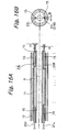
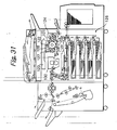
- the charger 122 uniformly charges the surface of the drum 121.
- the laser beam 123 scans the charged surface of the drum 121 to thereby form a latent image on the drum 121.
- the developing device 124 deposits charged toner on the latent image to thereby produce a corresponding toner image.
- the image transferring device 125 transfers the toner image from the drum 121 to a paper sheet or similar recording medium.
- the cleaning device, 127 removes the toner left on the drum 121 after the image transfer.
- the discharger 128 discharges potential left on the drum 121 for thereby preparing the drum 121 for another image formation.
- the image forming apparatus forms an image by negative-to-positive development. Then, after the charger 122 has uniformly charged the surface of the drum 121, the laser beam 123 forms a latent image on the drum 121.
- the developing device 124 develops the latent image to thereby form a corresponding toner image.
- the image transferring device 125 which includes a belt 129, transfers the toner image from the drum 121 to a paper sheet or similar recording medium, not shown, fed from a sheet bank 126 or an extra tray.
- the sheet bank 126 is arranged in the lower portion of the apparatus and includes a tandem tray, a universal tray, and a fixed tray. At this instant, a peeler peels off the paper sheet electrostatically adhering to the drum 121.
- the fixing device of the type described includes a belt 140 passed over a heat roller 141 accommodating the coils 11 through 13 and a fixing roller 142.
- the press roller 2 is pressed against the fixing roller 142.
- a tension roller 143 applies tension to the belt 140.
- a press roller is substituted for the tension roller 143 and conveys a paper sheet in cooperation with a belt.
- the coils 11 through 13 may be positioned at the side opposite to the press roller with respect to the belt.
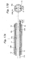
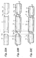
- the bobbin 6 is divided into a plurality of bobbin members, e.g., a main bobbin member 11 and auxiliary bobbin members 12 and 13 positioned at opposite sides of the main bobbin member 11.
- the main bobbin or center bobbin 11 is formed with recesses 11a at its opposite ends.
- the auxiliary bobbin members 12 and 13 are respectively formed with projections 12a and 13a at their one end.
- the recesses 11a and projections 12a and 13a are configured to mate with each other.
- conductors 14, 15 and 16 are wound round the bobbin members 11, 12 and 13, respectively.
- the conductors 14 through 16 may be implemented by stranded wires, if desired.
- the bobbin members 12 and 13 with the conductors 15 and 16 are connected to the center bobbin member 11 with the projections 12a and 13a mating with the recesses 11a, completing an induction heating coil 3.
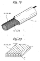
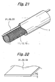
- the conductor 15 is wound round a core 17 with its opposite ends 15a held straight.
- the conductor 15 wound round the core 17 is inserted into the bobbin member 12 to thereby form a coil.
- the ends 15a of the conductor 15 are bent inward to complete the coil.
- the other bobbin members 11 and 13 are dealt with in the same manner as the bobbin member 12 in order to form respective coils.
- the resulting bobbin members 11 through 13 are coupled with their coils being connected to each other.
- the center coil 14 With a size corresponding to the A4 profile size and provide the entire coil assembly with a size corresponding to the A4 landscape size for the following reasons. Because current flows through the center coil 14 substantially throughout the operation of the fixing device, the coil 14 should preferably be arranged on the inner periphery of the bobbin member 11 and efficiently cooled.
- the end coils 12 and 13 may be arranged on the outer peripheries of the bobbin members 12 and 13 because current does not flow therethrough when the sheet size is equal to or smaller than the A4 profile size.
- FIG. 40 shows a modified bobbin 21.
- the bobbin-21 is formed with a projection 21a and a recess 21b at opposite ends thereof, respectively.
- a single bobbin may be assigned to each end bobbin member of FIG. 39 while four bobbins may be assigned to the center bobbin member.
Landscapes
- Physics & Mathematics (AREA)
- Electromagnetism (AREA)
- General Physics & Mathematics (AREA)
- General Induction Heating (AREA)
- Fixing For Electrophotography (AREA)
Claims (6)
- Induktionsheizspule (3) für eine Fixiervorrichtung (30) in einer Bilderzeugungsvorrichtung, die mehrere Haspeln (6, 6a, 6b), die aus einem wärmebeständigen Material gebildet sind, und mehrere Leiter (3a bis 3e), die um die Haspeln (6a, 6b) gewickelt sind, enthält,
dadurch gekennzeichnet, dass:um jede der mehreren Haspeln (6a; 6b) jeweils ein entsprechender Leiter (3a bis 3e) gewickelt ist und dass die Haspeln (6a; 6b) unterschiedliche Durchmesser besitzen und teleskopartig zusammengefügt sind. - Induktionsheizspule (3) nach Anspruch 1, wobei der Leiter (3a), der um die äußere Haspel (6a) gewickelt ist, die einen größeren Durchmesser als eine innere Haspel (6b) besitzt, eine Hauptspule ist, die hauptsächlich zu verwenden ist.
- Induktionsheizspule (3) nach Anspruch 1 oder 2, wobei jeder Leiter (3a bis 3e) über eine Breite gewickelt ist, die entweder einem Haupt- oder einem Hilfsschichtdurchgangsbereich entspricht.
- Induktionsheizspule (3) nach einem der Ansprüche 1 bis 3, wobei jeder Leiter (3a bis 3e) in einer schraubenlinienförmigen Nut aufgenommen ist, die in einem äußeren Umfang einer entsprechenden Haspel (6a, 6b) ausgebildet ist.
- Fixiervorrichtung (30) des Induktionsheiztyps, um ein Tonerbild auf einem Aufzeichnungsmedium zu fixieren, wobei die Vorrichtung (30) des Induktionsheiztyps umfasst:zwei Walzen (1, 2), um das Aufzeichnungsmedium zu befördern, während das Aufzeichnungsmedium im Walzenspalt eingeklemmt ist; undeine Induktionsheizspule (3) nach einem der Ansprüche 1 bis 4, wobei die Induktionsheizspule (3) wenigstens einer der beiden Walzen zugeordnet ist, um einen Induktionsmagnetfluss zu erzeugen.
- Bilderzeugungsvorrichtung, die eine Fixiervorrichtung (30) des Induktionsheiztyps nach Anspruch 5 enthält.
Applications Claiming Priority (10)
| Application Number | Priority Date | Filing Date | Title |
|---|---|---|---|
| JP2000130934 | 2000-04-28 | ||
| JP2000130935A JP2001312165A (ja) | 2000-04-28 | 2000-04-28 | 誘導コイルおよびその製造方法並びに画像形成装置 |
| JP2000130934 | 2000-04-28 | ||
| JP2000130935 | 2000-04-28 | ||
| JP2000231577 | 2000-07-31 | ||
| JP2000231577 | 2000-07-31 | ||
| JP2000238403A JP2002014561A (ja) | 2000-04-28 | 2000-08-07 | 誘導加熱コイルおよび画像形成装置 |
| JP2000238403 | 2000-08-07 | ||
| JP2001050654 | 2001-02-26 | ||
| JP2001050654A JP2002117967A (ja) | 2000-07-31 | 2001-02-26 | 誘導加熱コイル、誘導加熱型定着装置及び画像形成装置 |
Publications (3)
| Publication Number | Publication Date |
|---|---|
| EP1150180A2 EP1150180A2 (de) | 2001-10-31 |
| EP1150180A3 EP1150180A3 (de) | 2008-04-02 |
| EP1150180B1 true EP1150180B1 (de) | 2011-04-06 |
Family
ID=27531515
Family Applications (1)
| Application Number | Title | Priority Date | Filing Date |
|---|---|---|---|
| EP01110087A Expired - Lifetime EP1150180B1 (de) | 2000-04-28 | 2001-04-30 | Induktionsbeheizte Fixiervorrichtung für ein Bilderzeugungsgerät, sowie Induktionsheizspule hierfür |
Country Status (3)
| Country | Link |
|---|---|
| US (3) | US6753515B2 (de) |
| EP (1) | EP1150180B1 (de) |
| DE (1) | DE60144357D1 (de) |
Families Citing this family (26)
| Publication number | Priority date | Publication date | Assignee | Title |
|---|---|---|---|---|
| US6580896B2 (en) * | 2000-12-22 | 2003-06-17 | Samsung Electronics Co., Ltd. | Fusing roller assembly for electrophotographic image forming apparatus |
| US6816688B2 (en) * | 2002-01-02 | 2004-11-09 | Kabushiki Kaisha Toshiba | Image forming apparatus |
| JP2003323970A (ja) * | 2002-04-30 | 2003-11-14 | Harison Toshiba Lighting Corp | 誘導加熱装置、定着装置、および画像形成装置 |
| JP2004012804A (ja) * | 2002-06-06 | 2004-01-15 | Toshiba Tec Corp | 誘導加熱を用いた加熱装置ならびに定着装置 |
| KR100750546B1 (ko) * | 2002-06-26 | 2007-08-20 | 미쯔이 죠센 가부시키가이샤 | 유도 가열 방법 및 장치 |
| US6861630B2 (en) | 2003-03-07 | 2005-03-01 | Kabushiki Kaisha Toshiba | Heating device and fixing device |
| JP2004273337A (ja) * | 2003-03-11 | 2004-09-30 | Fuji Photo Film Co Ltd | 加熱ローラ、該加熱ローラを使用したカレンダー処理装置、及び該カレンダー処理装置を使用した磁気記録媒体の製造方法 |
| US7105784B2 (en) * | 2003-03-24 | 2006-09-12 | Kabushiki Kaisha Toshiba | Fixing device |
| US6861627B2 (en) * | 2003-03-26 | 2005-03-01 | Kabushiki Kaisha Toshiba | Induction heat fixing device |
| JP3929942B2 (ja) * | 2003-06-26 | 2007-06-13 | 株式会社リコー | 定着装置及び画像形成装置 |
| EP1530100B1 (de) * | 2003-10-22 | 2009-02-11 | Ricoh Company, Ltd. | Bilderzeugungsverfahren |
| US7323666B2 (en) * | 2003-12-08 | 2008-01-29 | Saint-Gobain Performance Plastics Corporation | Inductively heatable components |
| JP2006078809A (ja) * | 2004-09-10 | 2006-03-23 | Ricoh Co Ltd | 定着装置及び画像形成装置 |
| US7205513B2 (en) * | 2005-06-27 | 2007-04-17 | Xerox Corporation | Induction heated fuser and fixing members |
| US7459658B2 (en) * | 2005-08-31 | 2008-12-02 | Xerox Corporation | Drum heater systems and methods |
| KR100699255B1 (ko) * | 2005-09-15 | 2007-03-28 | 삼성전자주식회사 | 복수의 코일이 내장된 히팅롤러, 이를 포함하는 정착기 및화상형성장치 |
| JP2007310353A (ja) * | 2006-04-17 | 2007-11-29 | Ricoh Co Ltd | 定着装置及び画像形成装置 |
| JP4901343B2 (ja) | 2006-07-12 | 2012-03-21 | 株式会社リコー | 定着ローラ、定着装置、及び、画像形成装置 |
| US8700334B2 (en) * | 2006-07-31 | 2014-04-15 | International Business Machines Corporation | Methods and systems for reconstructing genomic common ancestors |
| US7855471B2 (en) * | 2007-03-15 | 2010-12-21 | Ricoh Company, Ltd. | Power supply device and image forming apparatus |
| DE102007054147A1 (de) * | 2007-11-12 | 2009-05-20 | Khs Ag | Leimwalze sowie Etikettieraggregat mit einer solchen Leimwalze |
| EP2336678A4 (de) * | 2008-09-17 | 2017-04-19 | Daikin Industries, Ltd. | Kühlmittelerwärmungsvorrichtung und montagestruktur dafür |
| JP2012042711A (ja) * | 2010-08-19 | 2012-03-01 | Konica Minolta Business Technologies Inc | 定着装置及び画像形成装置 |
| US10034330B2 (en) * | 2013-03-15 | 2018-07-24 | National Oilwell Varco, L.P. | System and method for heat treating a tubular |
| US10321524B2 (en) * | 2014-01-17 | 2019-06-11 | Nike, Inc. | Conveyance curing system |
| US12174561B2 (en) | 2020-03-26 | 2024-12-24 | Hewlett-Packard Development Company, L.P. | Heating for a printing drum |
Family Cites Families (28)
| Publication number | Priority date | Publication date | Assignee | Title |
|---|---|---|---|---|
| US2583854A (en) * | 1948-10-01 | 1952-01-29 | Siemens Ag | Inductance coil with ceramic form for high frequency |
| US3958328A (en) * | 1975-06-02 | 1976-05-25 | Essex International, Inc. | Method of making a transformer coil assembly |
| JPH07120555B2 (ja) * | 1990-05-31 | 1995-12-20 | 三菱電機株式会社 | ロール装置 |
| JPH04118890A (ja) * | 1990-09-06 | 1992-04-20 | Matsushita Electric Ind Co Ltd | 高周波加熱装置 |
| US5300996A (en) | 1991-06-07 | 1994-04-05 | Ricoh Company, Ltd. | Fixing apparatus |
| US5523550A (en) * | 1992-01-06 | 1996-06-04 | Kimura; Todd T. | Capacitive induction heating method and apparatus for the production for instant hot water and steam |
| US5304767A (en) * | 1992-11-13 | 1994-04-19 | Gas Research Institute | Low emission induction heating coil |
| JP3273453B2 (ja) | 1993-02-04 | 2002-04-08 | 株式会社リコー | 画像定着装置 |
| JP3337304B2 (ja) | 1994-02-23 | 2002-10-21 | 株式会社リコー | 定着装置 |
| JPH0844239A (ja) * | 1994-07-29 | 1996-02-16 | Fujitsu Ltd | シリアル型電子写真装置 |
| JPH08137306A (ja) | 1994-11-10 | 1996-05-31 | Minolta Co Ltd | 電磁誘導加熱式定着装置 |
| JP3103739B2 (ja) | 1994-12-27 | 2000-10-30 | 京セラ株式会社 | 定着装置 |
| US5822669A (en) * | 1995-08-29 | 1998-10-13 | Minolta Co., Ltd. | Induction heat fusing device |
| US5832354A (en) | 1995-12-05 | 1998-11-03 | Ricoh Company, Ltd. | Image fixing device, image forming apparatus providing the image fixing device and rotor used in the image fixing device and having induction coil inside |
| JPH1010901A (ja) | 1996-06-24 | 1998-01-16 | Ricoh Co Ltd | 定着装置における定着ローラ |
| JPH1020704A (ja) | 1996-06-28 | 1998-01-23 | Ricoh Co Ltd | 定着装置 |
| JPH10143009A (ja) * | 1996-11-08 | 1998-05-29 | Fuji Xerox Co Ltd | 温度検知装置及びこれを用いた定着装置 |
| GB2319583B (en) | 1996-11-25 | 1999-09-22 | Ricoh Kk | Device with induction heating roller |
| JP3621214B2 (ja) | 1996-11-25 | 2005-02-16 | 株式会社リコー | 加熱ローラ及びローラ加熱装置 |
| JPH10282826A (ja) | 1997-04-11 | 1998-10-23 | Ricoh Co Ltd | 誘導加熱定着装置 |
| JP4087498B2 (ja) * | 1998-04-30 | 2008-05-21 | 株式会社東芝 | 定着装置 |
| JPH11316509A (ja) | 1998-05-01 | 1999-11-16 | Toshiba Corp | 定着装置 |
| JP3997025B2 (ja) * | 1998-03-31 | 2007-10-24 | 株式会社リコー | 定着装置 |
| JP2000056598A (ja) | 1998-06-05 | 2000-02-25 | Ricoh Co Ltd | 定着装置 |
| JP2000066543A (ja) | 1998-08-25 | 2000-03-03 | Ricoh Co Ltd | 誘導加熱定着装置 |
| JP3559716B2 (ja) | 1998-09-25 | 2004-09-02 | 株式会社リコー | 誘導発熱型定着装置とその誘導電流発生部材を製造する方法 |
| JP2000105518A (ja) | 1998-09-29 | 2000-04-11 | Ricoh Co Ltd | 誘導加熱型定着装置 |
| JP4271790B2 (ja) * | 1999-09-22 | 2009-06-03 | 東芝テック株式会社 | 定着装置 |
-
2001
- 2001-04-27 US US09/842,880 patent/US6753515B2/en not_active Expired - Fee Related
- 2001-04-30 DE DE60144357T patent/DE60144357D1/de not_active Expired - Lifetime
- 2001-04-30 EP EP01110087A patent/EP1150180B1/de not_active Expired - Lifetime
-
2004
- 2004-03-29 US US10/810,834 patent/US6946629B2/en not_active Expired - Fee Related
-
2005
- 2005-07-08 US US11/176,188 patent/US7135660B2/en not_active Expired - Fee Related
Also Published As
| Publication number | Publication date |
|---|---|
| US20040188423A1 (en) | 2004-09-30 |
| DE60144357D1 (de) | 2011-05-19 |
| US20050242084A1 (en) | 2005-11-03 |
| EP1150180A2 (de) | 2001-10-31 |
| US6946629B2 (en) | 2005-09-20 |
| EP1150180A3 (de) | 2008-04-02 |
| US20020031381A1 (en) | 2002-03-14 |
| US7135660B2 (en) | 2006-11-14 |
| US6753515B2 (en) | 2004-06-22 |
Similar Documents
| Publication | Publication Date | Title |
|---|---|---|
| EP1150180B1 (de) | Induktionsbeheizte Fixiervorrichtung für ein Bilderzeugungsgerät, sowie Induktionsheizspule hierfür | |
| US6963718B2 (en) | Heating apparatus and image forming apparatus | |
| JP2004012804A (ja) | 誘導加熱を用いた加熱装置ならびに定着装置 | |
| JP3687439B2 (ja) | 誘導加熱定着装置 | |
| US7826785B2 (en) | Fixing device having an induction heating control member | |
| JPWO2002029498A1 (ja) | 像加熱装置および画像形成装置 | |
| US6252212B1 (en) | Image fixing apparatus with induction heating device and manufacturing method thereof | |
| JPH09258586A (ja) | 誘導加熱定着装置 | |
| US7319840B2 (en) | Induction heating fixing device and image forming apparatus | |
| JP3452920B2 (ja) | 像加熱装置及びこれを用いる画像形成装置 | |
| JP2000081806A (ja) | 定着装置 | |
| JP2004086205A (ja) | 像加熱装置および画像形成装置 | |
| US20080237223A1 (en) | Induction heating device and induction heating fixing device | |
| JP3426229B1 (ja) | 像加熱装置及びこれに用いる画像形成装置 | |
| US20060165444A1 (en) | Fixing apparatus | |
| US7835681B2 (en) | Induction heating device and induction heat fixing device | |
| JP2005166524A (ja) | 励磁コイル及びこれを用いた電磁誘導加熱装置、定着装置、画像形成装置 | |
| JP3324351B2 (ja) | 誘導加熱定着装置 | |
| JP3763542B2 (ja) | 誘導加熱定着装置 | |
| JP2001312165A (ja) | 誘導コイルおよびその製造方法並びに画像形成装置 | |
| JP3935657B2 (ja) | 定着装置および画像形成装置 | |
| JP2002014561A (ja) | 誘導加熱コイルおよび画像形成装置 | |
| JP2002229355A (ja) | 電磁誘導加熱コイル | |
| US8620200B2 (en) | Image forming apparatus and control method | |
| JP3032734U (ja) | 温度を自動調整可能な定着ローラー |
Legal Events
| Date | Code | Title | Description |
|---|---|---|---|
| PUAI | Public reference made under article 153(3) epc to a published international application that has entered the european phase |
Free format text: ORIGINAL CODE: 0009012 |
|
| 17P | Request for examination filed |
Effective date: 20010430 |
|
| AK | Designated contracting states |
Kind code of ref document: A2 Designated state(s): AT BE CH CY DE DK ES FI FR GB GR IE IT LI LU MC NL PT SE TR |
|
| AX | Request for extension of the european patent |
Free format text: AL;LT;LV;MK;RO;SI |
|
| PUAL | Search report despatched |
Free format text: ORIGINAL CODE: 0009013 |
|
| AK | Designated contracting states |
Kind code of ref document: A3 Designated state(s): AT BE CH CY DE DK ES FI FR GB GR IE IT LI LU MC NL PT SE TR |
|
| AX | Request for extension of the european patent |
Extension state: AL LT LV MK RO SI |
|
| 17Q | First examination report despatched |
Effective date: 20080617 |
|
| AKX | Designation fees paid |
Designated state(s): DE FR GB |
|
| GRAP | Despatch of communication of intention to grant a patent |
Free format text: ORIGINAL CODE: EPIDOSNIGR1 |
|
| GRAS | Grant fee paid |
Free format text: ORIGINAL CODE: EPIDOSNIGR3 |
|
| GRAA | (expected) grant |
Free format text: ORIGINAL CODE: 0009210 |
|
| AK | Designated contracting states |
Kind code of ref document: B1 Designated state(s): DE FR GB |
|
| REG | Reference to a national code |
Ref country code: GB Ref legal event code: FG4D |
|
| REF | Corresponds to: |
Ref document number: 60144357 Country of ref document: DE Date of ref document: 20110519 Kind code of ref document: P |
|
| REG | Reference to a national code |
Ref country code: DE Ref legal event code: R096 Ref document number: 60144357 Country of ref document: DE Effective date: 20110519 |
|
| PLBE | No opposition filed within time limit |
Free format text: ORIGINAL CODE: 0009261 |
|
| STAA | Information on the status of an ep patent application or granted ep patent |
Free format text: STATUS: NO OPPOSITION FILED WITHIN TIME LIMIT |
|
| 26N | No opposition filed |
Effective date: 20120110 |
|
| REG | Reference to a national code |
Ref country code: DE Ref legal event code: R097 Ref document number: 60144357 Country of ref document: DE Effective date: 20120110 |
|
| REG | Reference to a national code |
Ref country code: FR Ref legal event code: TP Owner name: RICOH COMPANY, LTD., JP Effective date: 20130618 |
|
| REG | Reference to a national code |
Ref country code: GB Ref legal event code: 732E Free format text: REGISTERED BETWEEN 20130815 AND 20130821 |
|
| PGFP | Annual fee paid to national office [announced via postgrant information from national office to epo] |
Ref country code: GB Payment date: 20140422 Year of fee payment: 14 |
|
| PGFP | Annual fee paid to national office [announced via postgrant information from national office to epo] |
Ref country code: FR Payment date: 20140422 Year of fee payment: 14 Ref country code: DE Payment date: 20140418 Year of fee payment: 14 |
|
| REG | Reference to a national code |
Ref country code: DE Ref legal event code: R119 Ref document number: 60144357 Country of ref document: DE |
|
| GBPC | Gb: european patent ceased through non-payment of renewal fee |
Effective date: 20150430 |
|
| PG25 | Lapsed in a contracting state [announced via postgrant information from national office to epo] |
Ref country code: GB Free format text: LAPSE BECAUSE OF NON-PAYMENT OF DUE FEES Effective date: 20150430 Ref country code: DE Free format text: LAPSE BECAUSE OF NON-PAYMENT OF DUE FEES Effective date: 20151103 |
|
| REG | Reference to a national code |
Ref country code: FR Ref legal event code: ST Effective date: 20151231 |
|
| PG25 | Lapsed in a contracting state [announced via postgrant information from national office to epo] |
Ref country code: FR Free format text: LAPSE BECAUSE OF NON-PAYMENT OF DUE FEES Effective date: 20150430 |