EP1149975A2 - Charnière de porte ou de fenêtre - Google Patents
Charnière de porte ou de fenêtre Download PDFInfo
- Publication number
- EP1149975A2 EP1149975A2 EP01110488A EP01110488A EP1149975A2 EP 1149975 A2 EP1149975 A2 EP 1149975A2 EP 01110488 A EP01110488 A EP 01110488A EP 01110488 A EP01110488 A EP 01110488A EP 1149975 A2 EP1149975 A2 EP 1149975A2
- Authority
- EP
- European Patent Office
- Prior art keywords
- door
- threaded part
- hinge
- bearing axis
- sleeve
- Prior art date
- Legal status (The legal status is an assumption and is not a legal conclusion. Google has not performed a legal analysis and makes no representation as to the accuracy of the status listed.)
- Granted
Links
Images

Classifications
-
- E—FIXED CONSTRUCTIONS
- E05—LOCKS; KEYS; WINDOW OR DOOR FITTINGS; SAFES
- E05D—HINGES OR SUSPENSION DEVICES FOR DOORS, WINDOWS OR WINGS
- E05D7/00—Hinges or pivots of special construction
- E05D7/0009—Adjustable hinges
- E05D7/0018—Adjustable hinges at the hinge axis
- E05D7/0027—Adjustable hinges at the hinge axis in an axial direction
-
- E—FIXED CONSTRUCTIONS
- E05—LOCKS; KEYS; WINDOW OR DOOR FITTINGS; SAFES
- E05D—HINGES OR SUSPENSION DEVICES FOR DOORS, WINDOWS OR WINGS
- E05D7/00—Hinges or pivots of special construction
- E05D7/0009—Adjustable hinges
- E05D7/0018—Adjustable hinges at the hinge axis
- E05D7/0045—Adjustable hinges at the hinge axis in a radial direction
- E05D7/0054—Adjustable hinges at the hinge axis in a radial direction by means of eccentric parts
-
- E—FIXED CONSTRUCTIONS
- E05—LOCKS; KEYS; WINDOW OR DOOR FITTINGS; SAFES
- E05Y—INDEXING SCHEME RELATING TO HINGES OR OTHER SUSPENSION DEVICES FOR DOORS, WINDOWS OR WINGS AND DEVICES FOR MOVING WINGS INTO OPEN OR CLOSED POSITION, CHECKS FOR WINGS AND WING FITTINGS NOT OTHERWISE PROVIDED FOR, CONCERNED WITH THE FUNCTIONING OF THE WING
- E05Y2900/00—Application of doors, windows, wings or fittings thereof
- E05Y2900/10—Application of doors, windows, wings or fittings thereof for buildings or parts thereof
- E05Y2900/13—Application of doors, windows, wings or fittings thereof for buildings or parts thereof characterised by the type of wing
- E05Y2900/132—Doors
-
- E—FIXED CONSTRUCTIONS
- E05—LOCKS; KEYS; WINDOW OR DOOR FITTINGS; SAFES
- E05Y—INDEXING SCHEME RELATING TO HINGES OR OTHER SUSPENSION DEVICES FOR DOORS, WINDOWS OR WINGS AND DEVICES FOR MOVING WINGS INTO OPEN OR CLOSED POSITION, CHECKS FOR WINGS AND WING FITTINGS NOT OTHERWISE PROVIDED FOR, CONCERNED WITH THE FUNCTIONING OF THE WING
- E05Y2900/00—Application of doors, windows, wings or fittings thereof
- E05Y2900/10—Application of doors, windows, wings or fittings thereof for buildings or parts thereof
- E05Y2900/13—Application of doors, windows, wings or fittings thereof for buildings or parts thereof characterised by the type of wing
- E05Y2900/148—Windows
Definitions
- the invention relates to a door or window hinge, with a frame hinge and a wing hinge, which means a pivot bearing axis are hinged together, with a threaded part that transfers wing load on the frame hinge is supported and with a wing-loaded sleeve is in thread engagement, and with rotary adjustment on the Swivel bearing axis, the rotation of which via a positive locking leads to an adjustment of the thread engagement.
- a hinge with the features mentioned above is known from DE 298 04 967 U.
- the wing loaded Sleeve that is torsionally positive with the swivel bearing axis is coupled, has an annular projection on which the Wing hinge supports.
- the wing-loaded sleeve on the one hand and the frame hinge on the other be adapted to each other in a special way.
- the invention is based on the object a door or window hinge with the aforementioned Features to improve so that there is a structural simplification of the belt in the support area between the wing-loaded Sleeve and the wing load-bearing threaded part results.
- Thread part surrounds the pivot bearing axis and with it in the Twisted form fit
- wing-loaded sleeve is a Roll tape sleeve is the one which causes the thread engagement Has thread.
- the wing load-bearing threaded part surrounds the pivot bearing axis and with her in the twisted form fit. This will Axial load transfer first achieved. The load transfer on the frame belt through the component closest to the axis, namely the threaded part surrounding the pivot axis. About that In addition, the threaded part engages directly in the wing-loaded A sleeve and forms that for the adjustment of the band necessary thread engagement.
- the wing-loaded sleeve formed as a roll tape sleeve, so it can be manufactured simply by means of a rolling process from strip material getting produced.
- the roll tape sleeves must, however not rolled from tape material, but they can also be lengths of extruded profiles, for example are made of aluminum.
- the tape material is suitable the necessary for the threaded engagement of the threaded part Take up thread.
- the above-described embodiment of the door or window hinge leads to a very slim Design, in the radial direction from the pivot bearing axis Direction in the area of the thread engagement only two components are necessary, namely those for weight absorption of the wing wing-loaded sleeve, which extends over the Thread engagement on the threaded part surrounding the pivot bearing axis as a second component.
- the roll tape sleeve is in each End has a thread.
- the roll tape sleeve be used for right / left stop, so that for the tape does not have two different roll tape sleeves available have to stand.
- the tape is designed so that the threaded part has a non-circular recess, in which engages the pivot bearing axis in a rotationally positive manner. It is therefore not necessary for a torsionally positive coupling both parts an additional acting between the two parts Install the driving part.
- the hinge can be characterized in that the non-circular recess of the threaded part and the non-circular formation the pivot bearing axis on the support side on the threaded part and are arranged on the pivot bearing axis.
- the area of the rotating band that is above the non-circular Recess of the threaded part and the non-circular design of the Swivel bearing axis is present, given in this area Be adapted to needs. In particular, it is possible train this area around. That makes it easier Training of the band in that area bearing or guide surfaces around the pivot bearing axis can be provided.
- a guide bushing encompassing the pivot bearing axis is installed in the upper end of the roll tape sleeve.
- the guide bush ensures a radial Support of the swivel bearing axis within the roller belt sleeve.
- it can be made of plastic be and so for a desired low coefficient of friction to care.
- the band can be designed so that the Guide bush has an annular collar that is flush with the face of the upper end of the roll tape sleeve is aligned. With one The guide bush can be placed in the roll band sleeve in the ring collar position exactly.
- the ring collar can also be used for this are used, hollow volumes in the area of the upper end of the Fill in the roll tape sleeve. Such a hollow volume is, for example an expansion of the bore of the roll tape sleeve.
- the guide bush has a has smooth cylindrical outer circumference, which is practically over the entire length of one located in the upper end of the roll tape sleeve Thread extends. With the guide bush the thread of the roll tape sleeve covered. The assembly of the Guide bushing and the roll tape sleeve is easy because the guide bushing can only be inserted into the roll tape sleeve got to.
- both overlapping ring projections Guide bushing and the threaded part can be within one be arranged annular cylindrical cavity, namely located between the pivot bearing axis and the roller conveyor. This results in mutual guidance of the guide bush and the threaded part between the pivot bearing axis and the roll tape sleeve.
- the overlapping telescoping ensures that a vertical adjustment of the threaded part not to a corresponding vertical adjustment of the guide bush leads, but the latter their place in the upper Retains end of the roll tape sleeve.
- the band can be designed so that a threaded engagement position of the threaded part and the roll tape sleeve by a locking screw penetrating both is secured. As a result, there is a relative twist of the threaded part to the roll tape sleeve excluded and the predetermined thread engagement and the resulting height position the roll tape sleeve guaranteed.
- the thread engagement position can be secured in such a way that that in the threaded part a predetermined number of vertical Elongated holes are arranged distributed over the circumference and / or the pivot bearing axis an end of the locking screw receiving annular groove.
- the predetermined number of Elongated holes result in a corresponding step-like adjustment of the thread engagement.
- the gradation is usually sufficient fine.
- a further embodiment of the band can consist in that the threaded part on the frame band side of its thread has a ring collar that is supported on the frame band serves. So that the contact surface of the threaded part on the Frame strap enlarged. Since the threaded part in the event of a Pivoting of the door leaf moved relative to the frame hinge, can reduce wear in this area become.
- the band can be designed accordingly be that the threaded part on a cap on the Frame tape is supported, which is the lower end of the roll tape sleeve enclosed.
- the cover cap can, for example be made of plastic. Since they're in the range of motion arranged between the threaded part and the frame band it helps reduce the frictional resistance. It also covers the gap that exists between the roll tape sleeve and the bearing part is present. As a result, the gap can do not interfere optically, especially not that its size in the case of height adjustment of the conveyor belt changes.
- the compression spring ensures that the cover cap always lies against the upper part of the frame hinge.
- axle bushings can Plastic exist and thus serve to reduce bearing friction which rotates when the wing pivots Pivot bearing axis. So that one acting on the axle bushings Take-along effect is avoided, the axle bushings secured by the band caps.
- conventional mass production parts as smooth cylindrical axle bushings on the outside can be used.
- the illustrated embodiment is in three parts Door hinge, consisting essentially of a hinge 12, which is articulated by means of a pivot bearing axis 13 a frame band 11 is connected, the upper part 11 ' and has a lower part 11 '' which are in one piece.
- a frame band 11 is connected, the upper part 11 ' and has a lower part 11 '' which are in one piece.
- a two-part Frame band could be formed.
- the frame strap 11 is on attached a frame of the door, not shown, for example at the specified attachment points 29, the as push-through holes for fastening screws, not shown are trained.
- the frame is, for example a hollow profile frame, on the folded end face the frame hinge 11 with a foot shown in FIG 30 is attached.
- the foot 30 sits on a bend 31 of the Frame hinge 11.
- the wing hinge 12 also has a foot 32, with fastening points 33 on a not shown Sash frame is attached, namely on a rabbet side Front face of the casement.
- the wing hinge 12 formed with an offset 34.
- the bends 31,34 reach through a gap between the neighboring ones Frame profiles in the rebate of these two frame profiles.
- the frame band 11 is on its two parts 11 ', 11' 'formed with bearing eyes, in their eye recesses Axle bushings 25 are arranged.
- the axle bushings 25 serve the storage of the ends 13 ', 13' 'of the pivot bearing axis 13, the is formed in one piece throughout.
- the frame band parts 11 ', 11' ' encloses a roll band sleeve 15 of the wing hinge 11 coaxially with the pivot axis 13 with distance.
- the annular space between the figures, which is not immediately apparent the roll tape sleeve 15 and the pivot bearing axis 13 is a this annular space essentially filling threaded part 14 arranged.
- the threaded part 14 extends from the lower End 15 '' of the roll tape sleeve 15 up over the middle thereof in the vicinity of a guide bush 19, which between the annular space the upper end 15 'of the roll tape sleeve 15 and Fills pivot axis 13.
- the threaded part 14 has a bottom collar 14 ', the protrudes radially outward and is on the lower part 11 '' of the frame hinge 11 is supported. Above the ring collar 14 ' the threaded part is provided on the outside with a thread 17 which engages in a thread 35 of the roll tape sleeve 15. The thread 35 is located at the lower end 15 '' of the roll tape sleeve 15, so that the roll tape sleeve 15 in the manner shown can support on the collar 15, the collar 15 of a guide flange 36 at least partially overlapped becomes.
- a thread 35 is also in the upper end 15 'of the roll band sleeve 15 available. It serves the possibility of the tape to be able to apply the other way around, so that it is for Right / left stop is suitable.
- the in the area of the thread 35 existing guide bush 19 covers the thread 35 Swivel bearing axis 13 down and serves the radial support axis 13.
- the guide bushing 19 and the threaded part 14 are each with an axially projecting telescopic collar 37.37 ' Mistake.
- the thickness of this collar is about the same size and half as large as the distance of the roll tape sleeve 14 to Pivot bearing axis 13.
- Fig.1 shows that the telescopic collar 37 in the telescopic collar 37 'of the guide bush 19 can intervene. This enables relative adjustments between the threaded part 14 and the guide bush 19 in the case a height adjustment of the hinge or wing hinge 12.
- a height adjustment of the wing hinge 12 relative to Frame strap 11 is through a thread engagement point of the threaded part 14 with its thread 17 in the thread 35 of Roll tape sleeve 15 allows.
- the thread 14 must be rotated become.
- the rotation is adjusted with the Swivel bearing axis 13.
- This has 13 'at its upper end Rotary adjustment means 16 in the form of a hexagon socket. If the pivot bearing axis with a in this hexagon recess engaging key twisted, so their Twist can be transmitted to the threaded part 14 since both are in a twisted form fit.
- the torsion fit is thereby causes the threaded part 14 to have a round recess 18 has, in which the pivot bearing axis 13 rotationally intervenes.
- the pivot bearing axis is also out of round training.
- the supervision of the non-circular, namely with flattened areas 38 provided pivot bearing axis 13 shows how the flattened and thus non-circular sections of the non-circular recess 18.
- a rotation of the pivot bearing axis 13 leads to one corresponding rotation of the threaded part 14 in the directions the double arrow 40 of Fig.3.
- the non-circular recess 18 of the threaded part 14 only about extends half the length, namely over the lower half length.
- the pivot bearing axis 13 is accordingly only provided with the flats 38 in this length range and above, ie in the upper area of the wing hinge 12, is the Swivel bearing axis 13 circular. However, it is possible to provide them here with flats 38. In one In this case, however, the guide bush 19 can remain round. The radial guidance is then also sufficient.
- the band 10 must be designed so that pivoting the door or window sash does not lead to an adjustment of the wing hinge 12 leads relative to the bearing hinge 11.
- a set screw 20 is used which is designed for example as a grub screw.
- the Locking screw 20 passes through the roll tape sleeve 15 and that Threaded part 14 according to Figure 3 and is against one end 20 screwed a bottom of an annular groove 28 of the pivot bearing axis 13.
- the locking screw 20 then prevents a relative Twisting the roll tape sleeve 15 and the threaded part 14.
- 14 elongated holes 21 are formed in the threaded part extend vertically according to Fig.1.
- the threaded part 14 is supported with its ring collar 14 'via a cover cap 22, on the axle bush 25 of the lower Frame hinge part 11 ''.
- the threaded part 14 has in all different height positions of the roll tape sleeve 15 the same Vertical position.
- the guide flange 36 forms with the Frame hinge part 11 '' a gap of different widths is 15, depending on the height of the roll tape sleeve is present on the cover cap 22 on the cover collar 39, with which the cover cap the lower end 15 '' of the roll tape sleeve 15 attached includes.
- the prescribed training of the tape 10 are primarily with regard to the height adjustment of the wing hinge 12 performed. However, it is also necessary to or pressure adjustments. Compression adjustment means that the tape is vertical to the sash level must be adjusted during a side adjustment horizontally parallel to the frame level.
- Compression adjustment means that the tape is vertical to the sash level must be adjusted during a side adjustment horizontally parallel to the frame level.
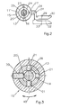
- the axle bushings 25 with eccentric mounting holes 24 provided around the ends 13 ', 13' 'of the pivot bearing axis 13 to be able to record. Fig.2 leaves the eccentricity the pivot bearing axis 13 relative to the outer circumference 25 'of Clearly recognize axle bushing 25.
- frame band parts 11 ', 11' 'and band caps 26 are formed.
- the longitudinal grooves 27 are even around the circumference and arranged symmetrically to the bends 31.
- the Ring grooves 27 can not shown projections of band caps 26 engage the upper end of the upper frame hinge part 11 'or on the lower end of the lower frame hinge part 11 ".
- the projections grip the band caps 26 also in a manner not shown in grooves of the axle bushings 25 and thus prevent their twisting, or they have an eccentric one according to the bearing axes With which they protrude into the eccentric mounting holes 24 intervene.
Applications Claiming Priority (2)
| Application Number | Priority Date | Filing Date | Title |
|---|---|---|---|
| DE20007759U DE20007759U1 (de) | 2000-04-28 | 2000-04-28 | Tür- oder Fensterband |
| DE20007759U | 2000-04-28 |
Publications (3)
| Publication Number | Publication Date |
|---|---|
| EP1149975A2 true EP1149975A2 (fr) | 2001-10-31 |
| EP1149975A3 EP1149975A3 (fr) | 2008-10-29 |
| EP1149975B1 EP1149975B1 (fr) | 2010-09-15 |
Family
ID=7940852
Family Applications (1)
| Application Number | Title | Priority Date | Filing Date |
|---|---|---|---|
| EP01110488A Expired - Lifetime EP1149975B1 (fr) | 2000-04-28 | 2001-04-27 | Charnière de porte ou de fenêtre |
Country Status (4)
| Country | Link |
|---|---|
| EP (1) | EP1149975B1 (fr) |
| AT (1) | ATE481545T1 (fr) |
| DE (2) | DE20007759U1 (fr) |
| PL (1) | PL204365B1 (fr) |
Cited By (2)
| Publication number | Priority date | Publication date | Assignee | Title |
|---|---|---|---|---|
| EP1452679A2 (fr) * | 2003-02-28 | 2004-09-01 | OTLAV SpA | Charnière pour éléments mobiles ou battants de meuble avec un mécanisme de réglage de la hauteur |
| EP2666943A1 (fr) * | 2012-05-23 | 2013-11-27 | Roto Frank Ag | Insert d'appui pour l'appui d'une fenêtre, d'une porte ou analogue |
Families Citing this family (2)
| Publication number | Priority date | Publication date | Assignee | Title |
|---|---|---|---|---|
| DE202005014093U1 (de) * | 2005-09-07 | 2007-01-18 | Dr. Hahn Gmbh & Co. Kg | Band für Türen, Fenster o.dgl. |
| DE102008049740B4 (de) | 2008-09-30 | 2016-08-04 | Eco Schulte Gmbh & Co. Kg | Höhenverstellbares Band |
Citations (1)
| Publication number | Priority date | Publication date | Assignee | Title |
|---|---|---|---|---|
| DE29804967U1 (de) | 1998-03-20 | 1999-07-22 | Niemann | Tür- oder Fensterband |
Family Cites Families (2)
| Publication number | Priority date | Publication date | Assignee | Title |
|---|---|---|---|---|
| GB623670A (en) * | 1943-06-01 | 1949-05-20 | Gustaf Adrian Weidelstam | Improvements in or relating to hinges |
| DE19528102C1 (de) * | 1995-08-01 | 1996-07-04 | Schlechtendahl & Soehne Wilh | Band für Türen, Fenster oder dergleichen |
-
2000
- 2000-04-28 DE DE20007759U patent/DE20007759U1/de not_active Expired - Lifetime
-
2001
- 2001-04-25 PL PL347263A patent/PL204365B1/pl unknown
- 2001-04-27 EP EP01110488A patent/EP1149975B1/fr not_active Expired - Lifetime
- 2001-04-27 AT AT01110488T patent/ATE481545T1/de active
- 2001-04-27 DE DE50115626T patent/DE50115626D1/de not_active Expired - Lifetime
Patent Citations (1)
| Publication number | Priority date | Publication date | Assignee | Title |
|---|---|---|---|---|
| DE29804967U1 (de) | 1998-03-20 | 1999-07-22 | Niemann | Tür- oder Fensterband |
Cited By (3)
| Publication number | Priority date | Publication date | Assignee | Title |
|---|---|---|---|---|
| EP1452679A2 (fr) * | 2003-02-28 | 2004-09-01 | OTLAV SpA | Charnière pour éléments mobiles ou battants de meuble avec un mécanisme de réglage de la hauteur |
| EP1452679A3 (fr) * | 2003-02-28 | 2005-08-17 | OTLAV SpA | Charnière pour éléments mobiles ou battants de meuble avec un mécanisme de réglage de la hauteur |
| EP2666943A1 (fr) * | 2012-05-23 | 2013-11-27 | Roto Frank Ag | Insert d'appui pour l'appui d'une fenêtre, d'une porte ou analogue |
Also Published As
| Publication number | Publication date |
|---|---|
| PL347263A1 (en) | 2001-11-05 |
| DE50115626D1 (de) | 2010-10-28 |
| ATE481545T1 (de) | 2010-10-15 |
| EP1149975B1 (fr) | 2010-09-15 |
| DE20007759U1 (de) | 2001-09-06 |
| EP1149975A3 (fr) | 2008-10-29 |
| PL204365B1 (pl) | 2010-01-29 |
Similar Documents
| Publication | Publication Date | Title |
|---|---|---|
| EP2209959A1 (fr) | Fermeture à compression | |
| EP1091066A2 (fr) | Charnière pour portes ou fenêtres | |
| WO2000014371A1 (fr) | Charniere a visser comportant une position d'arret | |
| DE3418138C2 (de) | Bandzapfenbüchse | |
| EP0750088B1 (fr) | Penture pour portes, fenêtres et similaires | |
| DE19642637C2 (de) | Türscharnier zur schwenkbaren Lagerung eines Türflügels an einem Türrahmen | |
| EP0318422B1 (fr) | Charnière réglable, en particulier pour portes | |
| EP1149975B1 (fr) | Charnière de porte ou de fenêtre | |
| EP2261448B1 (fr) | Charnière pour portes et fenêtres | |
| EP1331339A2 (fr) | Charnière pour portes, fenêtres et similaires | |
| EP1067266B1 (fr) | Charnière | |
| EP0893564B1 (fr) | Coussinet de pivotement pour fenêtre ou porteS | |
| EP0930411B1 (fr) | Penture de porte ou de fenêtre | |
| EP0212484B2 (fr) | Ferme-porte | |
| EP2740872B1 (fr) | Palier d'angle prévu pour l'agencement recouvert | |
| WO1999046465A1 (fr) | Penture a gond reglable en hauteur | |
| EP1245771B1 (fr) | Charnière pour portes ou fenêtres | |
| DE4405360C2 (de) | Beschlag zur schwenkbaren Befestigung des Flügels einer Tür oder eines Fensters an einem Rahmen | |
| EP0943770B1 (fr) | Penture de porte ou de fenêtre | |
| DE4405359C1 (de) | Beschlag zur schwenkbaren Befestigung eines Flügels einer Tür oder eines Fensters an einem Rahmen | |
| EP0662559B1 (fr) | Penture | |
| DE19607846C1 (de) | Band für Türen oder Fenster | |
| EP1050245B1 (fr) | Placard de coin avec un support pour un carrousel | |
| DE19832025B4 (de) | Höhenverstellbares Gelenkband | |
| DE7819147U1 (de) | Schliessvorrichtung fuer eine pendeltuer |
Legal Events
| Date | Code | Title | Description |
|---|---|---|---|
| PUAI | Public reference made under article 153(3) epc to a published international application that has entered the european phase |
Free format text: ORIGINAL CODE: 0009012 |
|
| AK | Designated contracting states |
Kind code of ref document: A2 Designated state(s): AT BE CH CY DE DK ES FI FR GB GR IE IT LI LU MC NL PT SE TR |
|
| AX | Request for extension of the european patent |
Free format text: AL;LT;LV;MK;RO;SI |
|
| PUAL | Search report despatched |
Free format text: ORIGINAL CODE: 0009013 |
|
| 17P | Request for examination filed |
Effective date: 20080807 |
|
| RAP1 | Party data changed (applicant data changed or rights of an application transferred) |
Owner name: GLUSKE-BKV GMBH |
|
| AK | Designated contracting states |
Kind code of ref document: A3 Designated state(s): AT BE CH CY DE DK ES FI FR GB GR IE IT LI LU MC NL PT SE TR |
|
| AX | Request for extension of the european patent |
Extension state: AL LT LV MK RO SI |
|
| AKX | Designation fees paid |
Designated state(s): AT BE CH CY DE DK ES FI FR GB GR IE IT LI LU MC NL PT SE TR |
|
| 17Q | First examination report despatched |
Effective date: 20090707 |
|
| GRAP | Despatch of communication of intention to grant a patent |
Free format text: ORIGINAL CODE: EPIDOSNIGR1 |
|
| GRAS | Grant fee paid |
Free format text: ORIGINAL CODE: EPIDOSNIGR3 |
|
| GRAA | (expected) grant |
Free format text: ORIGINAL CODE: 0009210 |
|
| AK | Designated contracting states |
Kind code of ref document: B1 Designated state(s): AT BE CH CY DE DK ES FI FR GB GR IE IT LI LU MC NL PT SE TR |
|
| REG | Reference to a national code |
Ref country code: GB Ref legal event code: FG4D Free format text: NOT ENGLISH Ref country code: CH Ref legal event code: EP |
|
| REG | Reference to a national code |
Ref country code: IE Ref legal event code: FG4D Free format text: LANGUAGE OF EP DOCUMENT: GERMAN |
|
| REF | Corresponds to: |
Ref document number: 50115626 Country of ref document: DE Date of ref document: 20101028 Kind code of ref document: P |
|
| REG | Reference to a national code |
Ref country code: NL Ref legal event code: VDEP Effective date: 20100915 |
|
| PG25 | Lapsed in a contracting state [announced via postgrant information from national office to epo] |
Ref country code: FI Free format text: LAPSE BECAUSE OF FAILURE TO SUBMIT A TRANSLATION OF THE DESCRIPTION OR TO PAY THE FEE WITHIN THE PRESCRIBED TIME-LIMIT Effective date: 20100915 |
|
| PG25 | Lapsed in a contracting state [announced via postgrant information from national office to epo] |
Ref country code: CY Free format text: LAPSE BECAUSE OF FAILURE TO SUBMIT A TRANSLATION OF THE DESCRIPTION OR TO PAY THE FEE WITHIN THE PRESCRIBED TIME-LIMIT Effective date: 20100915 |
|
| PG25 | Lapsed in a contracting state [announced via postgrant information from national office to epo] |
Ref country code: GR Free format text: LAPSE BECAUSE OF FAILURE TO SUBMIT A TRANSLATION OF THE DESCRIPTION OR TO PAY THE FEE WITHIN THE PRESCRIBED TIME-LIMIT Effective date: 20101216 Ref country code: SE Free format text: LAPSE BECAUSE OF FAILURE TO SUBMIT A TRANSLATION OF THE DESCRIPTION OR TO PAY THE FEE WITHIN THE PRESCRIBED TIME-LIMIT Effective date: 20100915 |
|
| REG | Reference to a national code |
Ref country code: IE Ref legal event code: FD4D |
|
| PG25 | Lapsed in a contracting state [announced via postgrant information from national office to epo] |
Ref country code: IE Free format text: LAPSE BECAUSE OF FAILURE TO SUBMIT A TRANSLATION OF THE DESCRIPTION OR TO PAY THE FEE WITHIN THE PRESCRIBED TIME-LIMIT Effective date: 20100915 |
|
| PG25 | Lapsed in a contracting state [announced via postgrant information from national office to epo] |
Ref country code: IT Free format text: LAPSE BECAUSE OF FAILURE TO SUBMIT A TRANSLATION OF THE DESCRIPTION OR TO PAY THE FEE WITHIN THE PRESCRIBED TIME-LIMIT Effective date: 20100915 Ref country code: PT Free format text: LAPSE BECAUSE OF FAILURE TO SUBMIT A TRANSLATION OF THE DESCRIPTION OR TO PAY THE FEE WITHIN THE PRESCRIBED TIME-LIMIT Effective date: 20110117 Ref country code: NL Free format text: LAPSE BECAUSE OF FAILURE TO SUBMIT A TRANSLATION OF THE DESCRIPTION OR TO PAY THE FEE WITHIN THE PRESCRIBED TIME-LIMIT Effective date: 20100915 |
|
| PG25 | Lapsed in a contracting state [announced via postgrant information from national office to epo] |
Ref country code: ES Free format text: LAPSE BECAUSE OF FAILURE TO SUBMIT A TRANSLATION OF THE DESCRIPTION OR TO PAY THE FEE WITHIN THE PRESCRIBED TIME-LIMIT Effective date: 20101226 |
|
| PLBE | No opposition filed within time limit |
Free format text: ORIGINAL CODE: 0009261 |
|
| STAA | Information on the status of an ep patent application or granted ep patent |
Free format text: STATUS: NO OPPOSITION FILED WITHIN TIME LIMIT |
|
| 26N | No opposition filed |
Effective date: 20110616 |
|
| PG25 | Lapsed in a contracting state [announced via postgrant information from national office to epo] |
Ref country code: DK Free format text: LAPSE BECAUSE OF FAILURE TO SUBMIT A TRANSLATION OF THE DESCRIPTION OR TO PAY THE FEE WITHIN THE PRESCRIBED TIME-LIMIT Effective date: 20100915 |
|
| PGFP | Annual fee paid to national office [announced via postgrant information from national office to epo] |
Ref country code: GB Payment date: 20110421 Year of fee payment: 11 |
|
| REG | Reference to a national code |
Ref country code: DE Ref legal event code: R081 Ref document number: 50115626 Country of ref document: DE Owner name: ROTO GLUSKE-BKV GMBH, DE Free format text: FORMER OWNER: GLUSKE-BKV GMBH, 42281 WUPPERTAL, DE Effective date: 20110708 |
|
| REG | Reference to a national code |
Ref country code: DE Ref legal event code: R097 Ref document number: 50115626 Country of ref document: DE Effective date: 20110616 |
|
| BERE | Be: lapsed |
Owner name: GLUSKE-BKV G.M.B.H. Effective date: 20110430 |
|
| PG25 | Lapsed in a contracting state [announced via postgrant information from national office to epo] |
Ref country code: MC Free format text: LAPSE BECAUSE OF NON-PAYMENT OF DUE FEES Effective date: 20110430 |
|
| REG | Reference to a national code |
Ref country code: CH Ref legal event code: PL |
|
| PG25 | Lapsed in a contracting state [announced via postgrant information from national office to epo] |
Ref country code: CH Free format text: LAPSE BECAUSE OF NON-PAYMENT OF DUE FEES Effective date: 20110430 Ref country code: BE Free format text: LAPSE BECAUSE OF NON-PAYMENT OF DUE FEES Effective date: 20110430 Ref country code: LI Free format text: LAPSE BECAUSE OF NON-PAYMENT OF DUE FEES Effective date: 20110430 |
|
| PGFP | Annual fee paid to national office [announced via postgrant information from national office to epo] |
Ref country code: FR Payment date: 20120507 Year of fee payment: 12 |
|
| GBPC | Gb: european patent ceased through non-payment of renewal fee |
Effective date: 20120427 |
|
| PG25 | Lapsed in a contracting state [announced via postgrant information from national office to epo] |
Ref country code: GB Free format text: LAPSE BECAUSE OF NON-PAYMENT OF DUE FEES Effective date: 20120427 |
|
| PGFP | Annual fee paid to national office [announced via postgrant information from national office to epo] |
Ref country code: AT Payment date: 20120411 Year of fee payment: 12 |
|
| PG25 | Lapsed in a contracting state [announced via postgrant information from national office to epo] |
Ref country code: LU Free format text: LAPSE BECAUSE OF NON-PAYMENT OF DUE FEES Effective date: 20110427 |
|
| PG25 | Lapsed in a contracting state [announced via postgrant information from national office to epo] |
Ref country code: TR Free format text: LAPSE BECAUSE OF FAILURE TO SUBMIT A TRANSLATION OF THE DESCRIPTION OR TO PAY THE FEE WITHIN THE PRESCRIBED TIME-LIMIT Effective date: 20100915 |
|
| REG | Reference to a national code |
Ref country code: AT Ref legal event code: MM01 Ref document number: 481545 Country of ref document: AT Kind code of ref document: T Effective date: 20130430 |
|
| PG25 | Lapsed in a contracting state [announced via postgrant information from national office to epo] |
Ref country code: AT Free format text: LAPSE BECAUSE OF NON-PAYMENT OF DUE FEES Effective date: 20130430 |
|
| REG | Reference to a national code |
Ref country code: FR Ref legal event code: ST Effective date: 20131231 |
|
| PG25 | Lapsed in a contracting state [announced via postgrant information from national office to epo] |
Ref country code: FR Free format text: LAPSE BECAUSE OF NON-PAYMENT OF DUE FEES Effective date: 20130430 |
|
| PGFP | Annual fee paid to national office [announced via postgrant information from national office to epo] |
Ref country code: DE Payment date: 20160506 Year of fee payment: 16 |
|
| REG | Reference to a national code |
Ref country code: DE Ref legal event code: R119 Ref document number: 50115626 Country of ref document: DE |
|
| PG25 | Lapsed in a contracting state [announced via postgrant information from national office to epo] |
Ref country code: DE Free format text: LAPSE BECAUSE OF NON-PAYMENT OF DUE FEES Effective date: 20171103 |
|
| REG | Reference to a national code |
Ref country code: DE Ref legal event code: R082 Ref document number: 50115626 Country of ref document: DE Representative=s name: CHRISTOPHERSEN PATENTANWAELTE, DE |