EP1149975A2 - Door hinge or window hinge - Google Patents
Door hinge or window hinge Download PDFInfo
- Publication number
- EP1149975A2 EP1149975A2 EP01110488A EP01110488A EP1149975A2 EP 1149975 A2 EP1149975 A2 EP 1149975A2 EP 01110488 A EP01110488 A EP 01110488A EP 01110488 A EP01110488 A EP 01110488A EP 1149975 A2 EP1149975 A2 EP 1149975A2
- Authority
- EP
- European Patent Office
- Prior art keywords
- door
- threaded part
- hinge
- bearing axis
- sleeve
- Prior art date
- Legal status (The legal status is an assumption and is not a legal conclusion. Google has not performed a legal analysis and makes no representation as to the accuracy of the status listed.)
- Granted
Links
Images

Classifications
-
- E—FIXED CONSTRUCTIONS
- E05—LOCKS; KEYS; WINDOW OR DOOR FITTINGS; SAFES
- E05D—HINGES OR SUSPENSION DEVICES FOR DOORS, WINDOWS OR WINGS
- E05D7/00—Hinges or pivots of special construction
- E05D7/0009—Adjustable hinges
- E05D7/0018—Adjustable hinges at the hinge axis
- E05D7/0027—Adjustable hinges at the hinge axis in an axial direction
-
- E—FIXED CONSTRUCTIONS
- E05—LOCKS; KEYS; WINDOW OR DOOR FITTINGS; SAFES
- E05D—HINGES OR SUSPENSION DEVICES FOR DOORS, WINDOWS OR WINGS
- E05D7/00—Hinges or pivots of special construction
- E05D7/0009—Adjustable hinges
- E05D7/0018—Adjustable hinges at the hinge axis
- E05D7/0045—Adjustable hinges at the hinge axis in a radial direction
- E05D7/0054—Adjustable hinges at the hinge axis in a radial direction by means of eccentric parts
-
- E—FIXED CONSTRUCTIONS
- E05—LOCKS; KEYS; WINDOW OR DOOR FITTINGS; SAFES
- E05Y—INDEXING SCHEME RELATING TO HINGES OR OTHER SUSPENSION DEVICES FOR DOORS, WINDOWS OR WINGS AND DEVICES FOR MOVING WINGS INTO OPEN OR CLOSED POSITION, CHECKS FOR WINGS AND WING FITTINGS NOT OTHERWISE PROVIDED FOR, CONCERNED WITH THE FUNCTIONING OF THE WING
- E05Y2900/00—Application of doors, windows, wings or fittings thereof
- E05Y2900/10—Application of doors, windows, wings or fittings thereof for buildings or parts thereof
- E05Y2900/13—Application of doors, windows, wings or fittings thereof for buildings or parts thereof characterised by the type of wing
- E05Y2900/132—Doors
-
- E—FIXED CONSTRUCTIONS
- E05—LOCKS; KEYS; WINDOW OR DOOR FITTINGS; SAFES
- E05Y—INDEXING SCHEME RELATING TO HINGES OR OTHER SUSPENSION DEVICES FOR DOORS, WINDOWS OR WINGS AND DEVICES FOR MOVING WINGS INTO OPEN OR CLOSED POSITION, CHECKS FOR WINGS AND WING FITTINGS NOT OTHERWISE PROVIDED FOR, CONCERNED WITH THE FUNCTIONING OF THE WING
- E05Y2900/00—Application of doors, windows, wings or fittings thereof
- E05Y2900/10—Application of doors, windows, wings or fittings thereof for buildings or parts thereof
- E05Y2900/13—Application of doors, windows, wings or fittings thereof for buildings or parts thereof characterised by the type of wing
- E05Y2900/148—Windows
Definitions
- the invention relates to a door or window hinge, with a frame hinge and a wing hinge, which means a pivot bearing axis are hinged together, with a threaded part that transfers wing load on the frame hinge is supported and with a wing-loaded sleeve is in thread engagement, and with rotary adjustment on the Swivel bearing axis, the rotation of which via a positive locking leads to an adjustment of the thread engagement.
- a hinge with the features mentioned above is known from DE 298 04 967 U.
- the wing loaded Sleeve that is torsionally positive with the swivel bearing axis is coupled, has an annular projection on which the Wing hinge supports.
- the wing-loaded sleeve on the one hand and the frame hinge on the other be adapted to each other in a special way.
- the invention is based on the object a door or window hinge with the aforementioned Features to improve so that there is a structural simplification of the belt in the support area between the wing-loaded Sleeve and the wing load-bearing threaded part results.
- Thread part surrounds the pivot bearing axis and with it in the Twisted form fit
- wing-loaded sleeve is a Roll tape sleeve is the one which causes the thread engagement Has thread.
- the wing load-bearing threaded part surrounds the pivot bearing axis and with her in the twisted form fit. This will Axial load transfer first achieved. The load transfer on the frame belt through the component closest to the axis, namely the threaded part surrounding the pivot axis. About that In addition, the threaded part engages directly in the wing-loaded A sleeve and forms that for the adjustment of the band necessary thread engagement.
- the wing-loaded sleeve formed as a roll tape sleeve, so it can be manufactured simply by means of a rolling process from strip material getting produced.
- the roll tape sleeves must, however not rolled from tape material, but they can also be lengths of extruded profiles, for example are made of aluminum.
- the tape material is suitable the necessary for the threaded engagement of the threaded part Take up thread.
- the above-described embodiment of the door or window hinge leads to a very slim Design, in the radial direction from the pivot bearing axis Direction in the area of the thread engagement only two components are necessary, namely those for weight absorption of the wing wing-loaded sleeve, which extends over the Thread engagement on the threaded part surrounding the pivot bearing axis as a second component.
- the roll tape sleeve is in each End has a thread.
- the roll tape sleeve be used for right / left stop, so that for the tape does not have two different roll tape sleeves available have to stand.
- the tape is designed so that the threaded part has a non-circular recess, in which engages the pivot bearing axis in a rotationally positive manner. It is therefore not necessary for a torsionally positive coupling both parts an additional acting between the two parts Install the driving part.
- the hinge can be characterized in that the non-circular recess of the threaded part and the non-circular formation the pivot bearing axis on the support side on the threaded part and are arranged on the pivot bearing axis.
- the area of the rotating band that is above the non-circular Recess of the threaded part and the non-circular design of the Swivel bearing axis is present, given in this area Be adapted to needs. In particular, it is possible train this area around. That makes it easier Training of the band in that area bearing or guide surfaces around the pivot bearing axis can be provided.
- a guide bushing encompassing the pivot bearing axis is installed in the upper end of the roll tape sleeve.
- the guide bush ensures a radial Support of the swivel bearing axis within the roller belt sleeve.
- it can be made of plastic be and so for a desired low coefficient of friction to care.
- the band can be designed so that the Guide bush has an annular collar that is flush with the face of the upper end of the roll tape sleeve is aligned. With one The guide bush can be placed in the roll band sleeve in the ring collar position exactly.
- the ring collar can also be used for this are used, hollow volumes in the area of the upper end of the Fill in the roll tape sleeve. Such a hollow volume is, for example an expansion of the bore of the roll tape sleeve.
- the guide bush has a has smooth cylindrical outer circumference, which is practically over the entire length of one located in the upper end of the roll tape sleeve Thread extends. With the guide bush the thread of the roll tape sleeve covered. The assembly of the Guide bushing and the roll tape sleeve is easy because the guide bushing can only be inserted into the roll tape sleeve got to.
- both overlapping ring projections Guide bushing and the threaded part can be within one be arranged annular cylindrical cavity, namely located between the pivot bearing axis and the roller conveyor. This results in mutual guidance of the guide bush and the threaded part between the pivot bearing axis and the roll tape sleeve.
- the overlapping telescoping ensures that a vertical adjustment of the threaded part not to a corresponding vertical adjustment of the guide bush leads, but the latter their place in the upper Retains end of the roll tape sleeve.
- the band can be designed so that a threaded engagement position of the threaded part and the roll tape sleeve by a locking screw penetrating both is secured. As a result, there is a relative twist of the threaded part to the roll tape sleeve excluded and the predetermined thread engagement and the resulting height position the roll tape sleeve guaranteed.
- the thread engagement position can be secured in such a way that that in the threaded part a predetermined number of vertical Elongated holes are arranged distributed over the circumference and / or the pivot bearing axis an end of the locking screw receiving annular groove.
- the predetermined number of Elongated holes result in a corresponding step-like adjustment of the thread engagement.
- the gradation is usually sufficient fine.
- a further embodiment of the band can consist in that the threaded part on the frame band side of its thread has a ring collar that is supported on the frame band serves. So that the contact surface of the threaded part on the Frame strap enlarged. Since the threaded part in the event of a Pivoting of the door leaf moved relative to the frame hinge, can reduce wear in this area become.
- the band can be designed accordingly be that the threaded part on a cap on the Frame tape is supported, which is the lower end of the roll tape sleeve enclosed.
- the cover cap can, for example be made of plastic. Since they're in the range of motion arranged between the threaded part and the frame band it helps reduce the frictional resistance. It also covers the gap that exists between the roll tape sleeve and the bearing part is present. As a result, the gap can do not interfere optically, especially not that its size in the case of height adjustment of the conveyor belt changes.
- the compression spring ensures that the cover cap always lies against the upper part of the frame hinge.
- axle bushings can Plastic exist and thus serve to reduce bearing friction which rotates when the wing pivots Pivot bearing axis. So that one acting on the axle bushings Take-along effect is avoided, the axle bushings secured by the band caps.
- conventional mass production parts as smooth cylindrical axle bushings on the outside can be used.
- the illustrated embodiment is in three parts Door hinge, consisting essentially of a hinge 12, which is articulated by means of a pivot bearing axis 13 a frame band 11 is connected, the upper part 11 ' and has a lower part 11 '' which are in one piece.
- a frame band 11 is connected, the upper part 11 ' and has a lower part 11 '' which are in one piece.
- a two-part Frame band could be formed.
- the frame strap 11 is on attached a frame of the door, not shown, for example at the specified attachment points 29, the as push-through holes for fastening screws, not shown are trained.
- the frame is, for example a hollow profile frame, on the folded end face the frame hinge 11 with a foot shown in FIG 30 is attached.
- the foot 30 sits on a bend 31 of the Frame hinge 11.
- the wing hinge 12 also has a foot 32, with fastening points 33 on a not shown Sash frame is attached, namely on a rabbet side Front face of the casement.
- the wing hinge 12 formed with an offset 34.
- the bends 31,34 reach through a gap between the neighboring ones Frame profiles in the rebate of these two frame profiles.
- the frame band 11 is on its two parts 11 ', 11' 'formed with bearing eyes, in their eye recesses Axle bushings 25 are arranged.
- the axle bushings 25 serve the storage of the ends 13 ', 13' 'of the pivot bearing axis 13, the is formed in one piece throughout.
- the frame band parts 11 ', 11' ' encloses a roll band sleeve 15 of the wing hinge 11 coaxially with the pivot axis 13 with distance.
- the annular space between the figures, which is not immediately apparent the roll tape sleeve 15 and the pivot bearing axis 13 is a this annular space essentially filling threaded part 14 arranged.
- the threaded part 14 extends from the lower End 15 '' of the roll tape sleeve 15 up over the middle thereof in the vicinity of a guide bush 19, which between the annular space the upper end 15 'of the roll tape sleeve 15 and Fills pivot axis 13.
- the threaded part 14 has a bottom collar 14 ', the protrudes radially outward and is on the lower part 11 '' of the frame hinge 11 is supported. Above the ring collar 14 ' the threaded part is provided on the outside with a thread 17 which engages in a thread 35 of the roll tape sleeve 15. The thread 35 is located at the lower end 15 '' of the roll tape sleeve 15, so that the roll tape sleeve 15 in the manner shown can support on the collar 15, the collar 15 of a guide flange 36 at least partially overlapped becomes.
- a thread 35 is also in the upper end 15 'of the roll band sleeve 15 available. It serves the possibility of the tape to be able to apply the other way around, so that it is for Right / left stop is suitable.
- the in the area of the thread 35 existing guide bush 19 covers the thread 35 Swivel bearing axis 13 down and serves the radial support axis 13.
- the guide bushing 19 and the threaded part 14 are each with an axially projecting telescopic collar 37.37 ' Mistake.
- the thickness of this collar is about the same size and half as large as the distance of the roll tape sleeve 14 to Pivot bearing axis 13.
- Fig.1 shows that the telescopic collar 37 in the telescopic collar 37 'of the guide bush 19 can intervene. This enables relative adjustments between the threaded part 14 and the guide bush 19 in the case a height adjustment of the hinge or wing hinge 12.
- a height adjustment of the wing hinge 12 relative to Frame strap 11 is through a thread engagement point of the threaded part 14 with its thread 17 in the thread 35 of Roll tape sleeve 15 allows.
- the thread 14 must be rotated become.
- the rotation is adjusted with the Swivel bearing axis 13.
- This has 13 'at its upper end Rotary adjustment means 16 in the form of a hexagon socket. If the pivot bearing axis with a in this hexagon recess engaging key twisted, so their Twist can be transmitted to the threaded part 14 since both are in a twisted form fit.
- the torsion fit is thereby causes the threaded part 14 to have a round recess 18 has, in which the pivot bearing axis 13 rotationally intervenes.
- the pivot bearing axis is also out of round training.
- the supervision of the non-circular, namely with flattened areas 38 provided pivot bearing axis 13 shows how the flattened and thus non-circular sections of the non-circular recess 18.
- a rotation of the pivot bearing axis 13 leads to one corresponding rotation of the threaded part 14 in the directions the double arrow 40 of Fig.3.
- the non-circular recess 18 of the threaded part 14 only about extends half the length, namely over the lower half length.
- the pivot bearing axis 13 is accordingly only provided with the flats 38 in this length range and above, ie in the upper area of the wing hinge 12, is the Swivel bearing axis 13 circular. However, it is possible to provide them here with flats 38. In one In this case, however, the guide bush 19 can remain round. The radial guidance is then also sufficient.
- the band 10 must be designed so that pivoting the door or window sash does not lead to an adjustment of the wing hinge 12 leads relative to the bearing hinge 11.
- a set screw 20 is used which is designed for example as a grub screw.
- the Locking screw 20 passes through the roll tape sleeve 15 and that Threaded part 14 according to Figure 3 and is against one end 20 screwed a bottom of an annular groove 28 of the pivot bearing axis 13.
- the locking screw 20 then prevents a relative Twisting the roll tape sleeve 15 and the threaded part 14.
- 14 elongated holes 21 are formed in the threaded part extend vertically according to Fig.1.
- the threaded part 14 is supported with its ring collar 14 'via a cover cap 22, on the axle bush 25 of the lower Frame hinge part 11 ''.
- the threaded part 14 has in all different height positions of the roll tape sleeve 15 the same Vertical position.
- the guide flange 36 forms with the Frame hinge part 11 '' a gap of different widths is 15, depending on the height of the roll tape sleeve is present on the cover cap 22 on the cover collar 39, with which the cover cap the lower end 15 '' of the roll tape sleeve 15 attached includes.
- the prescribed training of the tape 10 are primarily with regard to the height adjustment of the wing hinge 12 performed. However, it is also necessary to or pressure adjustments. Compression adjustment means that the tape is vertical to the sash level must be adjusted during a side adjustment horizontally parallel to the frame level.
- Compression adjustment means that the tape is vertical to the sash level must be adjusted during a side adjustment horizontally parallel to the frame level.
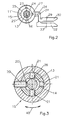
- the axle bushings 25 with eccentric mounting holes 24 provided around the ends 13 ', 13' 'of the pivot bearing axis 13 to be able to record. Fig.2 leaves the eccentricity the pivot bearing axis 13 relative to the outer circumference 25 'of Clearly recognize axle bushing 25.
- frame band parts 11 ', 11' 'and band caps 26 are formed.
- the longitudinal grooves 27 are even around the circumference and arranged symmetrically to the bends 31.
- the Ring grooves 27 can not shown projections of band caps 26 engage the upper end of the upper frame hinge part 11 'or on the lower end of the lower frame hinge part 11 ".
- the projections grip the band caps 26 also in a manner not shown in grooves of the axle bushings 25 and thus prevent their twisting, or they have an eccentric one according to the bearing axes With which they protrude into the eccentric mounting holes 24 intervene.
Abstract
Description
Die Erfindung bezieht sich auf ein Tür- oder Fensterband, mit einem Rahmenband und einem Flügelband, die mittels einer Schwenklagerachse gelenkig miteinander verbunden sind, mit einem Gewindeteil, das auf dem Rahmenband flügellastabtragend abgestützt ist und mit einer flügelbelasteten Hülse in Gewindeeingriff steht, und mit Drehverstellmitteln an der Schwenklagerachse, deren Verdrehung über einen Verdrehformschluß zu einer Verstellung des Gewindeeingriffs führt.The invention relates to a door or window hinge, with a frame hinge and a wing hinge, which means a pivot bearing axis are hinged together, with a threaded part that transfers wing load on the frame hinge is supported and with a wing-loaded sleeve is in thread engagement, and with rotary adjustment on the Swivel bearing axis, the rotation of which via a positive locking leads to an adjustment of the thread engagement.
Ein Türband mit den vorstehend genannten Merkmalen ist aus der DE 298 04 967 U bekannt. Die flügelbelastete Hülse, die mit der Schwenklagerachsesie verdrehformschlüssig gekoppelt ist, besitzt einen Ringvorsprung, auf dem sich das Flügelband abstützt. Infolge dieser Abstützung müssen die flügelbelastete Hülse einerseits und das Rahmenband andererseits in spezieller Weise aneinander angepaßt sein.A hinge with the features mentioned above is known from DE 298 04 967 U. The wing loaded Sleeve that is torsionally positive with the swivel bearing axis is coupled, has an annular projection on which the Wing hinge supports. As a result of this support, the wing-loaded sleeve on the one hand and the frame hinge on the other be adapted to each other in a special way.
Demgegenüber liegt der Erfindung die Aufgabe zugrunde, ein Tür- oder Fensterband mit den eingangs genannten Merkmalen so zu verbessern, daß sich eine bauliche Vereinfachung des Bandes in Abstützbereich zwischen der flügelbelasteten Hülse und dem flügellastabtragenden Gewindeteil ergibt.In contrast, the invention is based on the object a door or window hinge with the aforementioned Features to improve so that there is a structural simplification of the belt in the support area between the wing-loaded Sleeve and the wing load-bearing threaded part results.
Die vorgenannte Aufgabe wird dadurch gelöst, daß das Gewindeteil die Schwenklagerachse umgibt und mit ihr in dem Verdrehformschluß ist, und daß die flügelbelastete Hülse eine Rollbandhülse ist, die ein den Gewindeeingriff bewirkendes Gewinde aufweist.The above object is achieved in that the Thread part surrounds the pivot bearing axis and with it in the Twisted form fit, and that the wing-loaded sleeve is a Roll tape sleeve is the one which causes the thread engagement Has thread.
Für die Erfindung ist zunächst von Bedeutung, daß das flügellastabtragende Gewindeteil die Schwenklagerachse umgibt und mit ihr in dem Verdrehformschluß ist. Hierdurch wird zunächst eine achsiale Lastabtragung erreicht. Die Lastabtragung auf das Rahmenband erfolgt durch das achsnächste Bauteil, nämlich das die Schwenkachse umgebene Gewindeteil. Darüber hinaus greift das Gewindeteil direkt in die flügelbelastete Hülse ein und bildet den für die Verstellung des Bandes nötigen Gewindeeingriff. Dabei ist die flügelbelastete Hülse als Rollbandhülse ausgebildet, kann also in herstellungstechnisch einfacher Weise mittels eines Rollvorgangs aus Bandmaterial hergestellt werden. Die Rollbandhülsen müssen jedoch nicht aus Bandmaterial gerollt werden, sondern sie können auch Längenabschnitte extrudierter Profile sein, die beispielsweise aus Aluminium bestehen. Das Bandmaterial ist geeignet, das für den Gewindeeingriff des Gewindeteils notwendige Gewinde aufzunehmen. Die vorbeschriebene Ausführungsform des Tür- oder Fensterbandes führt zu einer sehr schlanken Bauform, bei der von der Schwenklagerachse aus in radialer Richtung im Bereich des Gewindeeingriffs lediglich zwei Bauteile erforderlich sind, nämlich die zur Aufnahme des Gewichts des Flügels flügelbelastete Hülse, die sich über den Gewindeeingriff auf dem die Schwenklagerachse umgebenden Gewindeteil als zweitem Bauteil abstützt.It is important for the invention that the wing load-bearing threaded part surrounds the pivot bearing axis and with her in the twisted form fit. This will Axial load transfer first achieved. The load transfer on the frame belt through the component closest to the axis, namely the threaded part surrounding the pivot axis. About that In addition, the threaded part engages directly in the wing-loaded A sleeve and forms that for the adjustment of the band necessary thread engagement. Here is the wing-loaded sleeve formed as a roll tape sleeve, so it can be manufactured simply by means of a rolling process from strip material getting produced. The roll tape sleeves must, however not rolled from tape material, but they can also be lengths of extruded profiles, for example are made of aluminum. The tape material is suitable the necessary for the threaded engagement of the threaded part Take up thread. The above-described embodiment of the door or window hinge leads to a very slim Design, in the radial direction from the pivot bearing axis Direction in the area of the thread engagement only two components are necessary, namely those for weight absorption of the wing wing-loaded sleeve, which extends over the Thread engagement on the threaded part surrounding the pivot bearing axis as a second component.
Es ist von Vorteil, wenn die Rollbandhülse in jedem Ende ein Gewinde aufweist. Infolgedessen kann die Rollbandhülse für Rechts/Links-Anschlag eingesetzt werden, so daß für das Band keine zwei unterschiedlichen Rollbandhülsen zur Verfügung stehen müssen.It is beneficial if the roll tape sleeve is in each End has a thread. As a result, the roll tape sleeve be used for right / left stop, so that for the tape does not have two different roll tape sleeves available have to stand.
Um den Verdrehformschluß der Schwenklagerachse und des Gewindeteils zu bewerkstelligen, wird das Band so ausgebildet, daß das Gewindeteil eine unrunde Ausnehmung hat, in die die Schwenklagerachse verdrehformschlüssig eingreift. Es ist daher nicht notwendig, zur verdrehformschlüssigen Kupplung beider Teile ein zwischen beiden Teilen wirkendes zusätzliches Mitnahmeteil einzubauen.To the torsion lock of the pivot bearing axis and of the threaded part, the tape is designed so that the threaded part has a non-circular recess, in which engages the pivot bearing axis in a rotationally positive manner. It is therefore not necessary for a torsionally positive coupling both parts an additional acting between the two parts Install the driving part.
In Ausgestaltung der vorbeschriebenen Ausbildung des Türbandes wird dieses so weitergebildet, daß sich die unrunde Ausnehmung des Gewindeteils etwa über dessen halbe Länge erstreckt und die Schwenklagerachse über dieselbe Länge entsprechend unrund ausgebildet ist. Damit werden großflächige Kontakte zwischen der Schwenklagerachse und dem Gewindeteil geschaffen. Es ergeben sich dementsprechend geringe Flächenpressungen, so daß eine Überlastungsgefahr entsprechend verringert wird. Es ist also nicht zu befürchten, daß sich der durch die Unrundheit gegebene Verdrehformschluß bei einer Benutzung des Bandes verschlechtert.In the design of the above training of Door hinge is further developed so that the non-circular Recess of the threaded part extends over about half its length and the pivot bearing axis over the same length accordingly is out of round. This will make large areas Contacts between the swivel bearing axis and the threaded part created. Accordingly, there are low surface pressures, so that an overload risk is reduced accordingly becomes. So there is no fear that the rotation due to the out-of-roundness when used of the tape deteriorated.
Das Türband kann dadurch gekennzeichnet sein, daß die unrunde Ausnehmung des Gewindeteils und die unrunde Ausbildung der Schwenklagerachse abstützseitig am Gewindeteil und an der Schwenklagerachse angeordnet sind. In diesem Fall kann derjenige Bereich des Drehbands, der oberhalb der unrunden Ausnehmung des Gewindeteils und der unrunden Ausbildung der Schwenklagerachse vorhanden ist, den in diesem Bereich gegebenen Bedürfnissen angepaßt werden. Insbesondere ist es möglich, diesen Bereich rund auszubilden. Das erleichtert die Ausbildung des Bandes dahingehend, daß in diesem Bereich rings um die Schwenklagerachse Lager- bzw. Führungsflächen vorgesehen sein können.The hinge can be characterized in that the non-circular recess of the threaded part and the non-circular formation the pivot bearing axis on the support side on the threaded part and are arranged on the pivot bearing axis. In this case the area of the rotating band that is above the non-circular Recess of the threaded part and the non-circular design of the Swivel bearing axis is present, given in this area Be adapted to needs. In particular, it is possible train this area around. That makes it easier Training of the band in that area bearing or guide surfaces around the pivot bearing axis can be provided.
Es ist zu bevorzugen, daß in das obere Ende der Rollbandhülse eine die Schwenklagerachse umfassende Führungsbuchse eingebaut ist. Die Führungsbuchse sorgt für eine radiale Abstützung der Schwenklagerachse innerhalb der Rollbandhülse. Sie kann beispielsweise aus Kunststoff ausgebildet sein und so für einen gewünschten geringen Reibungskoeffizienten sorgen.It is preferred that in the upper end of the roll tape sleeve a guide bushing encompassing the pivot bearing axis is installed. The guide bush ensures a radial Support of the swivel bearing axis within the roller belt sleeve. For example, it can be made of plastic be and so for a desired low coefficient of friction to care.
Das Band kann dahingehend ausgebildet werden, daß die Führungsbuchse einen Ringkragen hat, der mit der Stirnfläche des oberen Endes der Rollbandhülse fluchtet. Mit einem solchen Ringkragen läßt sich die Führungsbuchse in der Rollbandhülse exakt positionieren. Außerdem kann der Ringkragen dafür benutzt werden, Hohlvolumina im Bereich des oberen Endes der Rollbandhülse auszufüllen. Ein solches Hohlvolumen ist beispielsweise eine Erweiterung der Bohrung der Rollbandhülse.The band can be designed so that the Guide bush has an annular collar that is flush with the face of the upper end of the roll tape sleeve is aligned. With one The guide bush can be placed in the roll band sleeve in the ring collar position exactly. The ring collar can also be used for this are used, hollow volumes in the area of the upper end of the Fill in the roll tape sleeve. Such a hollow volume is, for example an expansion of the bore of the roll tape sleeve.
Vorteilhaft ist es, wenn daß die Führungsbuchse einen glattzylindrischen Außenumfang hat, der sich praktisch über die gesamte Länge eines im oberen Ende der Rollbandhülse befindlichen Gewindes erstreckt. Mit der Führungsbuchse wird das Gewinde der Rollbandhülse abgedeckt. Der Zusammenbau der Führungsbuchse und der Rollbandhülse ist einfach, da die Führungsbuchse lediglich in die Rollbandhülse eingesteckt werden muß.It is advantageous if the guide bush has a has smooth cylindrical outer circumference, which is practically over the entire length of one located in the upper end of the roll tape sleeve Thread extends. With the guide bush the thread of the roll tape sleeve covered. The assembly of the Guide bushing and the roll tape sleeve is easy because the guide bushing can only be inserted into the roll tape sleeve got to.
Weiterhin ist vorteilhaft, daß die Führungsbuchse und das Gewindeteil innerhalb der Rollbandhülse überlappend teleskopieren. Beide einander überlappende Ringvorsprünge der Führungsbuchse und des Gewindeteils können innerhalb eines ringzylindrischen Hohlraums angeordnet werden, der sich nämlich zwischen der Schwenklagerachse und dem Rollband befindet. Dabei ergibt sich eine gegenseitige Führung der Führungsbuchse und des Gewindeteils zwischen der Schwenklagerachse und der Rollbandhülse. Das überlappende Teleskopieren sorgt dafür, daß eine Vertikalverstellung des Gewindeteils nicht zu einer entsprechenden Vertikalverstellung der Führungsbuchse führt, sondern letztere ihren Platz im oberen Ende der Rollbandhülse beibehält. It is also advantageous that the guide bushing and Telescope the threaded part overlapping within the roll band sleeve. Both overlapping ring projections Guide bushing and the threaded part can be within one be arranged annular cylindrical cavity, namely located between the pivot bearing axis and the roller conveyor. This results in mutual guidance of the guide bush and the threaded part between the pivot bearing axis and the roll tape sleeve. The overlapping telescoping ensures that a vertical adjustment of the threaded part not to a corresponding vertical adjustment of the guide bush leads, but the latter their place in the upper Retains end of the roll tape sleeve.
Weiterhin kann das Band so ausgebildet werden, daß eine Gewindeeingriffstellung des Gewindeteil und der Rollbandhülse von einer beide durchdringenden Feststellschraube gesichert ist. Infolge dessen ist eine relative Verdrehung des Gewindeteils zur Rollbandhülse ausgeschlossen und der vorbestimmte Gewindeeingriff sowie die dadurch gegebene Höhenstellung der Rollbandhülse gewährleistet.Furthermore, the band can be designed so that a threaded engagement position of the threaded part and the roll tape sleeve by a locking screw penetrating both is secured. As a result, there is a relative twist of the threaded part to the roll tape sleeve excluded and the predetermined thread engagement and the resulting height position the roll tape sleeve guaranteed.
Eine konstruktive Ausgestaltung der vorbeschriebenen Sicherung der Gewindeeingriffsstellung kann dahingehend erfolgen, daß im Gewindeteil eine vorbestimmte Anzahl vertikaler Langlöcher über dessen Umfang verteilt angeordnet ist und/oder die Schwenklagerachse eine ein Ende der Feststellschraube aufnehmende Ringnut hat. Die vorbestimmte Anzahl der Langlöcher ergibt ein entsprechend stufenförmiges Verstellen des Gewindeeingriffs. Die Abstufung ist üblicher Weise ausreichend fein. Mit Hilfe der Ringnut läßt sich sicherstellen, daß die Schwenklagerachse axial gesichert ist. Bei montiertem und belastetem Band ist es damit ausgeschlossen, daß die Schwenklagerachse gewaltsam ausgetrieben werden kann, um den Türflügel zu entfernen.A constructive design of the above The thread engagement position can be secured in such a way that that in the threaded part a predetermined number of vertical Elongated holes are arranged distributed over the circumference and / or the pivot bearing axis an end of the locking screw receiving annular groove. The predetermined number of Elongated holes result in a corresponding step-like adjustment of the thread engagement. The gradation is usually sufficient fine. With the help of the ring groove it can be ensured that the pivot bearing axis is axially secured. When mounted and loaded tape, it is impossible that the Pivot bearing axis can be driven out by force To remove door panels.
Eine weitere Ausgestaltung des Bandes kann darin bestehen, daß das Gewindeteil rahmenbandseitig seines Gewindes einen Ringbund hat, der einer Abstützung auf dem Rahmenband dient. Damit wird die Auflagefläche des Gewindeteils auf dem Rahmenband vergrößert. Da sich das Gewindeteil im Falles eines Verschwenkens des Türflügels relativ zum Rahmenband bewegt, kann dadurch der Verschleiß in diesem Bereich verringert werden.A further embodiment of the band can consist in that the threaded part on the frame band side of its thread has a ring collar that is supported on the frame band serves. So that the contact surface of the threaded part on the Frame strap enlarged. Since the threaded part in the event of a Pivoting of the door leaf moved relative to the frame hinge, can reduce wear in this area become.
Weitergehend kann das Band dahingehend ausgestaltet werden, daß das Gewindeteil über eine Abdeckkappe auf dem Rahmenband abgestützt ist, die das untere Ende der Rollbandhülse anliegend umfaßt. Die Abdeckkappe kann beispielsweise aus Kunststoff ausgebildet werden. Da sie in dem Bewegungsbereich zwischen dem Gewindeteil und dem Rahmenband angeordnet ist, trägt sie dazu bei, den Reibungswiderstand zu verringern. Außerdem deckt sie den Spalt ab, der zwischen der Rollbandhülse und dem Lagerteil vorhanden ist. Der Spalt kann infolgedessen nicht optisch stören, vor allem nicht dadurch, daß er seine Größe im Falle der Höhenverstellung des Rollbandes ändert. Dabei gewährleistet die Druckfeder, daß die Abdeckkappe stets am oberen Teil des Rahmenbandes anliegt.In addition, the band can be designed accordingly be that the threaded part on a cap on the Frame tape is supported, which is the lower end of the roll tape sleeve enclosed. The cover cap can, for example be made of plastic. Since they're in the range of motion arranged between the threaded part and the frame band it helps reduce the frictional resistance. It also covers the gap that exists between the roll tape sleeve and the bearing part is present. As a result, the gap can do not interfere optically, especially not that its size in the case of height adjustment of the conveyor belt changes. The compression spring ensures that the cover cap always lies against the upper part of the frame hinge.
Insbesondere für dreiteilige Bänder ist es von Vorteil, daß daß die Enden der Schwenklagerachse jeweils in exzentrischen Aufnahmebohrungen von Achsbuchsen des Rahmenbandes radial gehalten sind, und daß die Achsbuchsen von mit dem Rahmenband verdrehformschlüssigen Bandkappen gegen ungewolltes Verdrehen gesichert sind. Die Achsbuchsen können aus Kunststoff bestehen und dienen so einer Verringerung der Lagerreibung der sich bei Schwenkbewegungen des Flügels drehenden Schwenklagerachse. Damit ein auf die Achsbuchsen einwirkender Mitnahmeeffekt vermieden wird, werden die Achsbuchsen von den Bandkappen gesichert. Es ergibt sich der Vorteil, daß als außen glattzylindrische Achsbuchsen herkömmliche Massenfertigungsteile eingesetzt werden können.It is particularly advantageous for three-part tapes that that the ends of the pivot bearing axis are each in eccentric Locating holes in the axle bushings of the frame hinge are held radially, and that the axle bushings from with the frame hinge twist-locking hinge caps against unwanted Are secured against twisting. The axle bushings can Plastic exist and thus serve to reduce bearing friction which rotates when the wing pivots Pivot bearing axis. So that one acting on the axle bushings Take-along effect is avoided, the axle bushings secured by the band caps. There is the advantage that conventional mass production parts as smooth cylindrical axle bushings on the outside can be used.
Wenn die Bandkappen in vier gleichmäßig voneinander beabstandeten Längsnuten des Rahmenbandes verdrehformschlüssig gehalten sind, ergeben sich vier Winkelstellungen der Bandkappen, wodurch sichergestellt werden kann, daß die Exzentrizität der Schwenklagerachse nur in vier unterschiedlichen Stellungen angeordnet werden kann. Dadurch wird ein unkontrolliertes Einstellen des Bands weitestgehend vermieden.When the band caps in four evenly apart spaced longitudinal grooves of the frame hinge twist are held, there are four angular positions Band caps, which can ensure that the eccentricity the pivot bearing axis only in four different Positions can be arranged. This becomes an uncontrolled one Adjustment of the band largely avoided.
Die Erfindung anhand eines in der Zeichnungs dargestellten Ausführungsbeispiels erläutert. Es zeigt:
- Fig.1
- einen Längsschnitt eines erfindungsmäßen Bandes,
- Fig.2
- eine Aufsicht auf das Band der Fig.1 bei angenommener Bandkappe, und
- Fig.3
- den Querschnitt I-I der Fig.1.
- Fig.1
- a longitudinal section of a tape according to the invention,
- Fig.2
- a view of the tape of Figure 1 with the tape cap adopted, and
- Figure 3
- the cross section II of Fig.1.
Das dargestellte Ausführungsbeispiel ist ein dreiteiligens
Türband, im wesentlichen bestehend aus einem Flügelband
12, das mittels einer Schwenklagerachse 13 gelenkig mit
einem Rahmenband 11 verbunden ist, das einen oberen Teil 11'
und einen unteren Teil 11'' aufweist, die einstückig sind.
Stattdessen könnten auch zwei einzelne Rahmenbänder vorhanden
sein, von denen eins die Schwenklagerachse 13 oben und eins
die Schwenklagerachse 13 unten lagert. Auch ein zweiteiliges
Rahmenband könnte ausgebildet sein. Das Rahmenband 11 ist an
einem nicht dargestellten Blendrahmen der Tür befestigt, beispielsweise
an den angegebenen Befestigungsstellen 29, die
als Durchstecklöcher für nicht dargestellte Befestigungsschrauben
ausgebildet sind. Der Blendrahmen ist beispielsweise
ein Hohlprofilrahmen, an dessen falzseitiger Stirnfläche
das Rahmenband 11 mit einem aus Fig.2 ersichtlichen Fuß
30 befestigt ist. Der Fuß 30 sitzt an einer Abkröpfung 31 des
Rahmenbands 11. Das Flügelband 12 besitzt ebenfalls einen Fuß
32, der mit Befestigungsstellen 33 an einem nicht dargestellten
Flügelrahmen befestigt ist, und zwar an einer falzseitigen
Stirnfläche des Flügelrahmens. Hierzu ist das Flügelband
12 mit einer Abkröpfung 34 ausgebildet. Die Abkröpfungen
31,34 greifen durch einen Spalt der einander benachbarten
Rahmenprofile in den Falzraum dieser beiden Rahmenprofile.The illustrated embodiment is in three parts
Door hinge, consisting essentially of a
Das Rahmenband 11 ist an seinen beiden Teilen
11',11'' mit Lageraugen ausgebildet, in deren Augenausnehmungen
Achsbuchsen 25 angeordnet sind. Die Achsbuchsen 25 dienen
der Lagerung der Enden 13',13'' der Schwenklagerachse 13, die
durchgehend einstückig ausgebildet ist. Zwischen den Lageraugen
der Rahmenbandteile 11',11'' umschließt eine Rollbandhülse
15 des Flügelbands 11 gleichachsig die Schwenkachse 13
mit Abstand. In dem infolge diesen Abstands gebildeten, aus
den Figuren nicht unmittelbar ersichtlichen Ringraum zwischen
der Rollbandhülse 15 und der Schwenklagerachse 13 ist ein
diesen Ringraum im wesentlichen ausfüllendes Gewindeteil 14
angeordnet. Das Gewindeteil 14 erstreckt sich vom unteren
Ende 15'' der Rollbandhülse 15 über deren Mitte nach oben bis
in die Nähe einer Führungsbuchse 19, die den Ringraum zwischen
den oberen Ende 15' der Rollbandhülse 15 und der
Schwenkachse 13 ausfüllt.The
Das Gewindeteil 14 hat unten einen Rinbund 14', der
radial nach außen vorspringt und sich auf dem unteren Teil
11'' des Rahmenbands 11 abstützt. Oberhalb des Ringbunds 14'
ist das Gewindeteil außen mit einem Gewinde 17 versehen, das
in ein Gewinde 35 der Rollbandhülse 15 eingreift. Das Gewinde
35 befindet sich am unteren Ende 15'' der Rollbandhülse 15,
so daß sich die Rollbandhülse 15 in der dargestellten Weise
auf dem Ringbund 15 abstützen kann, wobei der Ringbund 15 von
einem Führungsflansch 36 zumindest teilweise übergriffen
wird.The threaded
Ein Gewinde 35 ist auch im oberen Ende 15' der Rollbandhülse
15 vorhanden. Es dient der Möglichkeit, das Band
auch anders herum anwenden zu können, so daß es für
Rechts/Links-Anschlag geeignet ist. Die im Bereich des Gewindes
35 vorhandene Führungsbuchse 19 deckt das Gewinde 35 zur
Schwenklagerachse 13 hin ab und dient dabei der radialen Abstützung
der Achse 13.A
Die Führungsbuchse 19 und das Gewindeteil 14 sind jeweils
mit einem axial vorspringenden Teleskopkragen 37,37'
versehen. Die Dicke dieser Kragen ist etwa gleich groß und
dabei halb so groß, wie der Abstand der Rollbandhülse 14 zur
Schwenklagerachse 13. Die Teleskopkragen 37,37' sind so angeordnet,
daß sie ineinander greifen. Fig.1 zeigt, daß der Teleskopkragen
37 in den Teleskopkragen 37' der Führungsbuchse
19 eingreifen kann. Das ermöglicht Relativverstellungen zwischen
dem Gewindeteil 14 und der Führungsbuchse 19 im Fall
einer Höheneinstellung des Bandes bzw. des Flügelbands 12.The
Eine Höheneinstellung des Flügelbands 12 relativ zum
Rahmenband 11 wird durch eine Gewindeeingriffsstelle des Gewindeteils
14 mit seinem Gewinde 17 in das Gewinde 35 der
Rollbandhülse 15 ermöglicht. Hierzu muß das Gewinde 14 drehverstellt
werden. Die Drehverstellung erfolgt mit der
Schwenklagerachse 13. Diese hat an ihren oberen Ende 13'
Drehverstellmittel 16 in Gestalt einer Innensechskantausnehmung.
Wird die Schwenklagerachse mit einem in diese Sechskantausnehmung
eingreifenden Schlüssel verdreht, so kann ihre
Verdrehung auf das Gewindeteil 14 übertragen werden, da beide
in einem Verdrehformschluß sind. Der Verdrehformschluß wird
dadurch bewirkt, daß das Gewindeteil 14 eine runde Ausnehmung
18 hat, in die die Schwenklagerachse 13 verdrehformschlüssig
eingreift. Dementsprechend ist die Schwenklagerachse ebenfalls
unrund ausgebildet. Das ist aus Fig.3 ersichtlich, die
eine Aufsicht auf die unrunde, nämlich mit Abflachungen 38
versehene Schwenklagerachse 13 zeigt, wie auch die abgeflachten
und damit unrunden Abschnitte der unrunden Ausnehmung 18.
Eine Verdrehung der Schwenklagerachse 13 führt also zu einer
entsprechenden Verdrehung des Gewindeteils 14 in den Richtungen
des Doppelpfeils 40 der Fig.3. Dafür genügt es, wenn sich
die unrunde Ausnehmung 18 des Gewindeteils 14 nur etwa über
die halbe Länge erstreckt, nämlich über die untere halbe Länge.
Dabei ist die Schwenklagerachse 13 entsprechend auch nur
in diesem Längenbereich mit den Abflachungen 38 versehen und
oberhalb, also im oberen Bereich des Flügelbandes 12, ist die
Schwenklagerachse 13 kreisrund. Es ist allerdings möglich,
sie auch hier mit Abflachungen 38 zu versehen. In einem solchen
Fall kann die Führungsbuchse 19 jedoch rund bleiben.
Die radiale Führung ist dann ebenfalls genügend.A height adjustment of the
Das Band 10 muß so ausgebildet sein, daß ein Verschwenken
des Tür- oder Fensterflügels nicht zu einer Verstellung
des Flügelbands 12 relativ zum Lagerband 11 führt.
Um das zu erreichen, wird eine Feststellschraube 20 benutzt,
die beispielsweise als Madenschraube ausgebildet ist. Die
Feststellschraube 20 durchgreift die Rollbandhülse 15 und das
Gewindeteil 14 gemäß Fig.3 und wird mit einem Ende 20 gegen
einen Boden einer Ringnut 28 der Schwenklagerachse 13 geschraubt.
Die Feststellschraube 20 verhindert dann ein relatives
Verdrehen der Rollbandhülse 15 und des Gewindeteils 14.
Um die relative Höhenverstellung beider zu berücksichtigen,
sind in dem Gewindeteil 14 Langlöcher 21 ausgebildet, die
sich gemäß Fig.1 vertikal erstrecken. Nach einem Entfernen
der Feststellschraube 20 aus dem Gewindeteil 14 ist es daher
möglich, dieses zu verdrehen. Infolgedessen kommt eines der
anderen Langlöcher oder das ursprüngliche in eine Stellung,
in der die Feststellschraube 20 wieder eingeschraubt werden
kann. Vier Langlöcher sind ausreichend, um bei üblichen Steigungen
der Gewinde 17,35 eine hinreichend feine Höhenabstufung
zu erhalten.The
Das Gewindeteil 14 stützt sich mit seinem Ringbund
14' über eine Abdeckkappe 22, auf der Achsbuchse 25 des unteren
Rahmenbandteils 11'' ab. Das Gewindeteil 14 hat bei allen
unterschiedlichen Höhenstellungen der Rollbandhülse 15 dieselbe
Vertikalstellung. Der Führungsflansch 36 bildet mit dem
Rahmenbandteil 11'' einen Spalt, der unterschiedlich weit
ist, je nach Höhenstellung der Rollbandhülse 15. Infolgedessen
ist an der Abdeckkappe 22 an Abdeckkragen 39 vorhanden,
mit dem die Abdeckkappe das untere Ende 15'' der Rollbandhülse
15 anliegend umfaßt. Infolge des Abstützens des Gewindeteils
14 auf der Abdeckkappe 22 bleibt diese stets in der
dargestellten Stellung am Rahmenbandteil 11'.The threaded
Auch am oberen Rahmenbandteil 11' ist eine Abdeckkappe
22 vorhanden, da sich auch hier ein zwischen dem oberen
Ende 15' der Rollbandhülse 15 und dem Lagerteil 11' vorhandener
Spalt in Abhängigkeit von der Höhenstellung der Rollbandhülse
15 ändert. Der Abdeckkragen 39 der Abdeckkappe 22 verhindert,
daß ein sich ändernder Spalt optisch bemerkt werden
kann. Das äußere Aussehen des Bandes ist dementsprechend verbessert.
Es muß allerdings dafür gesorgt werden, daß die obere
Abdeckkappe 22 die hier in Fig.1 dargestellte Stellung
beibehält. Hierzu ist eine Druckfeder 23 vorhanden, die sich
an der Führungsbuchse 19 abstützt. Die Führungsbuchse 19 ist
hierzu mit der dargestellten Ringvertiefung ausgebildet, in
die die Druckfeder 23 mit einem Ende 23' eingesteckt ist. Zur
Ausbildung der Ringvertiefung hat die Führungsbuchse 19 genügend
Raum, da hier der Ringkragen 19' ausgebildet ist. Dieser
kann das Ende 23' der Druckfeder 23 auch klemmen, falls er in
das obere Ende 15' der Rollbandhülse 15 eingepreßt ist.There is also a cover cap on the upper frame hinge part 11 '
22 available, since there is also a space between the upper one
Die vorgeschriebenen Ausbildungen des Bandes 10 sind
in erster Linie im Hinblick auf die Höhenverstellung des Flügelbandes
12 durchgeführt. Es ist jedoch auch notwendig, Seiten-
oder Andruckverstellungen durchzuführen. Andruckverstellung
bedeutet, daß sich das Band vertikal zur Flügelrahmenebene
verstellen lassen muß, während eine Seitenverstellung
horizontal parallel zur Rahmenebene erfolgt. Um das zu ermöglichen,
sind die Achsbuchsen 25 mit exzentrischen Aufnahmebohrungen
24 versehen, um die Enden 13',13'' der Schwenklagerachse
13 aufnehmen zu können. Fig.2 läßt die Exzentizität
der Schwenklagerachse 13 relativ zum Außenumfang 25' der
Achsbuchse 25 deutlich erkennen.The prescribed training of the
Um die Achsbuchse 25 innerhalb der Rahmenbandteile
11', 11'' in vorbestimmten Stellungen positionieren zu können,
werden in besonderer Weise ausgebildete Rahmenbandteile
11',11'' und Bandkappen 26 ausgebildet. In den Rahmenbandteilen
11',11'' sind Längsnuten 27 vorhanden, und zwar jeweils
vier Stück. Die Längsnuten 27 sind gleichmäßig um den Umfang
und symmetrisch zu den Abkröpfungen 31 angeordnet. In die
Ringnuten 27 können nicht dargestellte Vorsprünge von Bandkappen
26 eingreifen, die auf das obere Ende des oberen Rahmenbandteils
11' bzw. auf das untere Ende des unteren Rahmenbandteils
11" gesteckt werden. Andererseits greifen die Vorsprünge
der Bandkappen 26 auch in nicht dargestellter Weise
in Nuten der Achsbuchsen 25 ein und verhindern so deren Verdrehen,
oder sie haben einen den Lagerachsen entsprechend exzentrischen
Vorsprung, mit dem sie in die exzentrischen Aufnahmebohrungen
24 eingreifen.Around the
Werden die Achsbuchsen 25 aus der Fig.2 dargestellten
Stellung um 180° gedreht angeordnet, so ergibt sich eine Andruckverstellung,
bei der der Flügel um die doppelte Exzentrizität
der Schwenklagerachse 13 parallel zur Ebene des Rahmens
versetzt wird. Ist das Band innenseitig angeordnet, wird
der Andruck entsprechend verstärkt. Falls die Achsbuchsen 25
in der gemäß Fig.2 oberen oder unteren Stellung angeordnet
werden, ergibt sich eine entsprechende Seitenverstellung des
Flügels relativ zum Blendrahmen. Liegt die Exzentrizität
oberhalb der Horizontalen, haben die Schuhe 30,32 einen
größeren Abstand voneinander, so daß der Falzraum entsprechend
vergrößert ist. Umgekehrt wird er verkleinert, wenn die
Exzentrizität oberhalb der Horizontalen liegt.Are the
Claims (16)
Applications Claiming Priority (2)
| Application Number | Priority Date | Filing Date | Title |
|---|---|---|---|
| DE20007759U DE20007759U1 (en) | 2000-04-28 | 2000-04-28 | Door or window hinge |
| DE20007759U | 2000-04-28 |
Publications (3)
| Publication Number | Publication Date |
|---|---|
| EP1149975A2 true EP1149975A2 (en) | 2001-10-31 |
| EP1149975A3 EP1149975A3 (en) | 2008-10-29 |
| EP1149975B1 EP1149975B1 (en) | 2010-09-15 |
Family
ID=7940852
Family Applications (1)
| Application Number | Title | Priority Date | Filing Date |
|---|---|---|---|
| EP01110488A Expired - Lifetime EP1149975B1 (en) | 2000-04-28 | 2001-04-27 | Door hinge or window hinge |
Country Status (4)
| Country | Link |
|---|---|
| EP (1) | EP1149975B1 (en) |
| AT (1) | ATE481545T1 (en) |
| DE (2) | DE20007759U1 (en) |
| PL (1) | PL204365B1 (en) |
Cited By (2)
| Publication number | Priority date | Publication date | Assignee | Title |
|---|---|---|---|---|
| EP1452679A2 (en) * | 2003-02-28 | 2004-09-01 | OTLAV SpA | Hinge for mobile elements or furniture wings with mechanism to adjust height |
| EP2666943A1 (en) * | 2012-05-23 | 2013-11-27 | Roto Frank Ag | Bearing insert for a bearing of a window, door or similar |
Families Citing this family (2)
| Publication number | Priority date | Publication date | Assignee | Title |
|---|---|---|---|---|
| DE202005014093U1 (en) * | 2005-09-07 | 2007-01-18 | Dr. Hahn Gmbh & Co. Kg | Hinge, e.g. for swing doors and windows, has a threaded bush around the hinge pin which can be displaced on the swing axis |
| DE102008049740B4 (en) | 2008-09-30 | 2016-08-04 | Eco Schulte Gmbh & Co. Kg | Height adjustable band |
Citations (1)
| Publication number | Priority date | Publication date | Assignee | Title |
|---|---|---|---|---|
| DE29804967U1 (en) | 1998-03-20 | 1999-07-22 | Niemann | Door or window hinge |
Family Cites Families (2)
| Publication number | Priority date | Publication date | Assignee | Title |
|---|---|---|---|---|
| GB623670A (en) * | 1943-06-01 | 1949-05-20 | Gustaf Adrian Weidelstam | Improvements in or relating to hinges |
| DE19528102C1 (en) * | 1995-08-01 | 1996-07-04 | Schlechtendahl & Soehne Wilh | Door or window hinge with adjustable bush for pin |
-
2000
- 2000-04-28 DE DE20007759U patent/DE20007759U1/en not_active Expired - Lifetime
-
2001
- 2001-04-25 PL PL347263A patent/PL204365B1/en unknown
- 2001-04-27 EP EP01110488A patent/EP1149975B1/en not_active Expired - Lifetime
- 2001-04-27 DE DE50115626T patent/DE50115626D1/en not_active Expired - Lifetime
- 2001-04-27 AT AT01110488T patent/ATE481545T1/en active
Patent Citations (1)
| Publication number | Priority date | Publication date | Assignee | Title |
|---|---|---|---|---|
| DE29804967U1 (en) | 1998-03-20 | 1999-07-22 | Niemann | Door or window hinge |
Cited By (3)
| Publication number | Priority date | Publication date | Assignee | Title |
|---|---|---|---|---|
| EP1452679A2 (en) * | 2003-02-28 | 2004-09-01 | OTLAV SpA | Hinge for mobile elements or furniture wings with mechanism to adjust height |
| EP1452679A3 (en) * | 2003-02-28 | 2005-08-17 | OTLAV SpA | Hinge for mobile elements or furniture wings with mechanism to adjust height |
| EP2666943A1 (en) * | 2012-05-23 | 2013-11-27 | Roto Frank Ag | Bearing insert for a bearing of a window, door or similar |
Also Published As
| Publication number | Publication date |
|---|---|
| DE50115626D1 (en) | 2010-10-28 |
| DE20007759U1 (en) | 2001-09-06 |
| ATE481545T1 (en) | 2010-10-15 |
| PL204365B1 (en) | 2010-01-29 |
| PL347263A1 (en) | 2001-11-05 |
| EP1149975B1 (en) | 2010-09-15 |
| EP1149975A3 (en) | 2008-10-29 |
Similar Documents
| Publication | Publication Date | Title |
|---|---|---|
| DE1559987B2 (en) | HINGES FOR WINDOWS OR DOORS | |
| EP2209959A1 (en) | Compression closure | |
| EP1091066A2 (en) | Hinge for doors or windows | |
| EP1109983A1 (en) | Screw-on hinge with blocked position | |
| DE3418138C2 (en) | Hinge pin bushing | |
| EP0750088B1 (en) | Hinge for doors, windows and the like | |
| DE19642637C2 (en) | Door hinge for the pivotable mounting of a door leaf on a door frame | |
| EP0318422B1 (en) | Adjustable hinge, especially for doors | |
| EP1149975B1 (en) | Door hinge or window hinge | |
| EP2261448B1 (en) | Hinge for doors and window | |
| EP1331339A2 (en) | Hinge for doors, windows and the like | |
| EP1067266B1 (en) | Hinge | |
| EP0893564B1 (en) | Pivot bearing for windows or doors | |
| EP0930411B1 (en) | Door or window hinge | |
| EP0212484B2 (en) | Door closer | |
| EP2740872B1 (en) | Corner bearing for concealed assembly | |
| WO1999046465A1 (en) | Screw-hook hinge adjustable in height | |
| EP1245771B1 (en) | Hinge for doors or windows | |
| EP1223275B1 (en) | Hinge for doors or windows | |
| EP0943770B1 (en) | Door or window hinge | |
| DE4405359C1 (en) | Fitment for swivel fixing door or window | |
| EP0662559B1 (en) | Doorhinge | |
| DE19607846C1 (en) | Hinge for door or window in building | |
| EP1050245B1 (en) | Corner cupboard with a mounting for a carrousel | |
| EP0942136B1 (en) | Height adjustable hinge pin support |
Legal Events
| Date | Code | Title | Description |
|---|---|---|---|
| PUAI | Public reference made under article 153(3) epc to a published international application that has entered the european phase |
Free format text: ORIGINAL CODE: 0009012 |
|
| AK | Designated contracting states |
Kind code of ref document: A2 Designated state(s): AT BE CH CY DE DK ES FI FR GB GR IE IT LI LU MC NL PT SE TR |
|
| AX | Request for extension of the european patent |
Free format text: AL;LT;LV;MK;RO;SI |
|
| PUAL | Search report despatched |
Free format text: ORIGINAL CODE: 0009013 |
|
| 17P | Request for examination filed |
Effective date: 20080807 |
|
| RAP1 | Party data changed (applicant data changed or rights of an application transferred) |
Owner name: GLUSKE-BKV GMBH |
|
| AK | Designated contracting states |
Kind code of ref document: A3 Designated state(s): AT BE CH CY DE DK ES FI FR GB GR IE IT LI LU MC NL PT SE TR |
|
| AX | Request for extension of the european patent |
Extension state: AL LT LV MK RO SI |
|
| AKX | Designation fees paid |
Designated state(s): AT BE CH CY DE DK ES FI FR GB GR IE IT LI LU MC NL PT SE TR |
|
| 17Q | First examination report despatched |
Effective date: 20090707 |
|
| GRAP | Despatch of communication of intention to grant a patent |
Free format text: ORIGINAL CODE: EPIDOSNIGR1 |
|
| GRAS | Grant fee paid |
Free format text: ORIGINAL CODE: EPIDOSNIGR3 |
|
| GRAA | (expected) grant |
Free format text: ORIGINAL CODE: 0009210 |
|
| AK | Designated contracting states |
Kind code of ref document: B1 Designated state(s): AT BE CH CY DE DK ES FI FR GB GR IE IT LI LU MC NL PT SE TR |
|
| REG | Reference to a national code |
Ref country code: GB Ref legal event code: FG4D Free format text: NOT ENGLISH Ref country code: CH Ref legal event code: EP |
|
| REG | Reference to a national code |
Ref country code: IE Ref legal event code: FG4D Free format text: LANGUAGE OF EP DOCUMENT: GERMAN |
|
| REF | Corresponds to: |
Ref document number: 50115626 Country of ref document: DE Date of ref document: 20101028 Kind code of ref document: P |
|
| REG | Reference to a national code |
Ref country code: NL Ref legal event code: VDEP Effective date: 20100915 |
|
| PG25 | Lapsed in a contracting state [announced via postgrant information from national office to epo] |
Ref country code: FI Free format text: LAPSE BECAUSE OF FAILURE TO SUBMIT A TRANSLATION OF THE DESCRIPTION OR TO PAY THE FEE WITHIN THE PRESCRIBED TIME-LIMIT Effective date: 20100915 |
|
| PG25 | Lapsed in a contracting state [announced via postgrant information from national office to epo] |
Ref country code: CY Free format text: LAPSE BECAUSE OF FAILURE TO SUBMIT A TRANSLATION OF THE DESCRIPTION OR TO PAY THE FEE WITHIN THE PRESCRIBED TIME-LIMIT Effective date: 20100915 |
|
| PG25 | Lapsed in a contracting state [announced via postgrant information from national office to epo] |
Ref country code: GR Free format text: LAPSE BECAUSE OF FAILURE TO SUBMIT A TRANSLATION OF THE DESCRIPTION OR TO PAY THE FEE WITHIN THE PRESCRIBED TIME-LIMIT Effective date: 20101216 Ref country code: SE Free format text: LAPSE BECAUSE OF FAILURE TO SUBMIT A TRANSLATION OF THE DESCRIPTION OR TO PAY THE FEE WITHIN THE PRESCRIBED TIME-LIMIT Effective date: 20100915 |
|
| REG | Reference to a national code |
Ref country code: IE Ref legal event code: FD4D |
|
| PG25 | Lapsed in a contracting state [announced via postgrant information from national office to epo] |
Ref country code: IE Free format text: LAPSE BECAUSE OF FAILURE TO SUBMIT A TRANSLATION OF THE DESCRIPTION OR TO PAY THE FEE WITHIN THE PRESCRIBED TIME-LIMIT Effective date: 20100915 |
|
| PG25 | Lapsed in a contracting state [announced via postgrant information from national office to epo] |
Ref country code: IT Free format text: LAPSE BECAUSE OF FAILURE TO SUBMIT A TRANSLATION OF THE DESCRIPTION OR TO PAY THE FEE WITHIN THE PRESCRIBED TIME-LIMIT Effective date: 20100915 Ref country code: PT Free format text: LAPSE BECAUSE OF FAILURE TO SUBMIT A TRANSLATION OF THE DESCRIPTION OR TO PAY THE FEE WITHIN THE PRESCRIBED TIME-LIMIT Effective date: 20110117 Ref country code: NL Free format text: LAPSE BECAUSE OF FAILURE TO SUBMIT A TRANSLATION OF THE DESCRIPTION OR TO PAY THE FEE WITHIN THE PRESCRIBED TIME-LIMIT Effective date: 20100915 |
|
| PG25 | Lapsed in a contracting state [announced via postgrant information from national office to epo] |
Ref country code: ES Free format text: LAPSE BECAUSE OF FAILURE TO SUBMIT A TRANSLATION OF THE DESCRIPTION OR TO PAY THE FEE WITHIN THE PRESCRIBED TIME-LIMIT Effective date: 20101226 |
|
| PLBE | No opposition filed within time limit |
Free format text: ORIGINAL CODE: 0009261 |
|
| STAA | Information on the status of an ep patent application or granted ep patent |
Free format text: STATUS: NO OPPOSITION FILED WITHIN TIME LIMIT |
|
| 26N | No opposition filed |
Effective date: 20110616 |
|
| PG25 | Lapsed in a contracting state [announced via postgrant information from national office to epo] |
Ref country code: DK Free format text: LAPSE BECAUSE OF FAILURE TO SUBMIT A TRANSLATION OF THE DESCRIPTION OR TO PAY THE FEE WITHIN THE PRESCRIBED TIME-LIMIT Effective date: 20100915 |
|
| PGFP | Annual fee paid to national office [announced via postgrant information from national office to epo] |
Ref country code: GB Payment date: 20110421 Year of fee payment: 11 |
|
| REG | Reference to a national code |
Ref country code: DE Ref legal event code: R081 Ref document number: 50115626 Country of ref document: DE Owner name: ROTO GLUSKE-BKV GMBH, DE Free format text: FORMER OWNER: GLUSKE-BKV GMBH, 42281 WUPPERTAL, DE Effective date: 20110708 |
|
| REG | Reference to a national code |
Ref country code: DE Ref legal event code: R097 Ref document number: 50115626 Country of ref document: DE Effective date: 20110616 |
|
| BERE | Be: lapsed |
Owner name: GLUSKE-BKV G.M.B.H. Effective date: 20110430 |
|
| PG25 | Lapsed in a contracting state [announced via postgrant information from national office to epo] |
Ref country code: MC Free format text: LAPSE BECAUSE OF NON-PAYMENT OF DUE FEES Effective date: 20110430 |
|
| REG | Reference to a national code |
Ref country code: CH Ref legal event code: PL |
|
| PG25 | Lapsed in a contracting state [announced via postgrant information from national office to epo] |
Ref country code: CH Free format text: LAPSE BECAUSE OF NON-PAYMENT OF DUE FEES Effective date: 20110430 Ref country code: BE Free format text: LAPSE BECAUSE OF NON-PAYMENT OF DUE FEES Effective date: 20110430 Ref country code: LI Free format text: LAPSE BECAUSE OF NON-PAYMENT OF DUE FEES Effective date: 20110430 |
|
| PGFP | Annual fee paid to national office [announced via postgrant information from national office to epo] |
Ref country code: FR Payment date: 20120507 Year of fee payment: 12 |
|
| GBPC | Gb: european patent ceased through non-payment of renewal fee |
Effective date: 20120427 |
|
| PG25 | Lapsed in a contracting state [announced via postgrant information from national office to epo] |
Ref country code: GB Free format text: LAPSE BECAUSE OF NON-PAYMENT OF DUE FEES Effective date: 20120427 |
|
| PGFP | Annual fee paid to national office [announced via postgrant information from national office to epo] |
Ref country code: AT Payment date: 20120411 Year of fee payment: 12 |
|
| PG25 | Lapsed in a contracting state [announced via postgrant information from national office to epo] |
Ref country code: LU Free format text: LAPSE BECAUSE OF NON-PAYMENT OF DUE FEES Effective date: 20110427 |
|
| PG25 | Lapsed in a contracting state [announced via postgrant information from national office to epo] |
Ref country code: TR Free format text: LAPSE BECAUSE OF FAILURE TO SUBMIT A TRANSLATION OF THE DESCRIPTION OR TO PAY THE FEE WITHIN THE PRESCRIBED TIME-LIMIT Effective date: 20100915 |
|
| REG | Reference to a national code |
Ref country code: AT Ref legal event code: MM01 Ref document number: 481545 Country of ref document: AT Kind code of ref document: T Effective date: 20130430 |
|
| PG25 | Lapsed in a contracting state [announced via postgrant information from national office to epo] |
Ref country code: AT Free format text: LAPSE BECAUSE OF NON-PAYMENT OF DUE FEES Effective date: 20130430 |
|
| REG | Reference to a national code |
Ref country code: FR Ref legal event code: ST Effective date: 20131231 |
|
| PG25 | Lapsed in a contracting state [announced via postgrant information from national office to epo] |
Ref country code: FR Free format text: LAPSE BECAUSE OF NON-PAYMENT OF DUE FEES Effective date: 20130430 |
|
| PGFP | Annual fee paid to national office [announced via postgrant information from national office to epo] |
Ref country code: DE Payment date: 20160506 Year of fee payment: 16 |
|
| REG | Reference to a national code |
Ref country code: DE Ref legal event code: R119 Ref document number: 50115626 Country of ref document: DE |
|
| PG25 | Lapsed in a contracting state [announced via postgrant information from national office to epo] |
Ref country code: DE Free format text: LAPSE BECAUSE OF NON-PAYMENT OF DUE FEES Effective date: 20171103 |
|
| REG | Reference to a national code |
Ref country code: DE Ref legal event code: R082 Ref document number: 50115626 Country of ref document: DE Representative=s name: CHRISTOPHERSEN PATENTANWAELTE, DE |