EP1331339A2 - Hinge for doors, windows and the like - Google Patents
Hinge for doors, windows and the like Download PDFInfo
- Publication number
- EP1331339A2 EP1331339A2 EP03010070A EP03010070A EP1331339A2 EP 1331339 A2 EP1331339 A2 EP 1331339A2 EP 03010070 A EP03010070 A EP 03010070A EP 03010070 A EP03010070 A EP 03010070A EP 1331339 A2 EP1331339 A2 EP 1331339A2
- Authority
- EP
- European Patent Office
- Prior art keywords
- hinge
- hinge pin
- axis
- pin bushing
- hinge part
- Prior art date
- Legal status (The legal status is an assumption and is not a legal conclusion. Google has not performed a legal analysis and makes no representation as to the accuracy of the status listed.)
- Granted
Links
Images

Classifications
-
- E—FIXED CONSTRUCTIONS
- E05—LOCKS; KEYS; WINDOW OR DOOR FITTINGS; SAFES
- E05D—HINGES OR SUSPENSION DEVICES FOR DOORS, WINDOWS OR WINGS
- E05D7/00—Hinges or pivots of special construction
- E05D7/0009—Adjustable hinges
- E05D7/0018—Adjustable hinges at the hinge axis
- E05D7/0045—Adjustable hinges at the hinge axis in a radial direction
- E05D2007/0081—Adjustable hinges at the hinge axis in a radial direction with swinging or rolling sleeves
-
- E—FIXED CONSTRUCTIONS
- E05—LOCKS; KEYS; WINDOW OR DOOR FITTINGS; SAFES
- E05D—HINGES OR SUSPENSION DEVICES FOR DOORS, WINDOWS OR WINGS
- E05D7/00—Hinges or pivots of special construction
- E05D7/0009—Adjustable hinges
- E05D7/0018—Adjustable hinges at the hinge axis
- E05D7/0045—Adjustable hinges at the hinge axis in a radial direction
- E05D7/0054—Adjustable hinges at the hinge axis in a radial direction by means of eccentric parts
-
- E—FIXED CONSTRUCTIONS
- E05—LOCKS; KEYS; WINDOW OR DOOR FITTINGS; SAFES
- E05Y—INDEXING SCHEME RELATING TO HINGES OR OTHER SUSPENSION DEVICES FOR DOORS, WINDOWS OR WINGS AND DEVICES FOR MOVING WINGS INTO OPEN OR CLOSED POSITION, CHECKS FOR WINGS AND WING FITTINGS NOT OTHERWISE PROVIDED FOR, CONCERNED WITH THE FUNCTIONING OF THE WING
- E05Y2900/00—Application of doors, windows, wings or fittings thereof
- E05Y2900/10—Application of doors, windows, wings or fittings thereof for buildings or parts thereof
- E05Y2900/13—Application of doors, windows, wings or fittings thereof for buildings or parts thereof characterised by the type of wing
- E05Y2900/132—Doors
-
- E—FIXED CONSTRUCTIONS
- E05—LOCKS; KEYS; WINDOW OR DOOR FITTINGS; SAFES
- E05Y—INDEXING SCHEME RELATING TO HINGES OR OTHER SUSPENSION DEVICES FOR DOORS, WINDOWS OR WINGS AND DEVICES FOR MOVING WINGS INTO OPEN OR CLOSED POSITION, CHECKS FOR WINGS AND WING FITTINGS NOT OTHERWISE PROVIDED FOR, CONCERNED WITH THE FUNCTIONING OF THE WING
- E05Y2900/00—Application of doors, windows, wings or fittings thereof
- E05Y2900/10—Application of doors, windows, wings or fittings thereof for buildings or parts thereof
- E05Y2900/13—Application of doors, windows, wings or fittings thereof for buildings or parts thereof characterised by the type of wing
- E05Y2900/148—Windows
Definitions
- the invention relates to a volume of the preamble of claim 1 corresponding Art.
- Such a band is the subject of DE 40 22 532 C1, in which the Guide part of the hinge pin not sliding in a parallel delimited recess, but in the recess around a parallel to the hinge axis Axis is arranged rolling.
- A serves to bring about the relocation Screw, which is arranged in the recess itself, the hinge pin reaches through and accessible from the side of the hinge part of the wing hinge part is.
- the screw only engages the hinge pin at one point, so that the precision of the guide depends on the precision of the screw bearing.
- the invention has for its object a generic tape which means the means for adjusting the hinge pin in the hinge part or its recess are arranged so that the guide the hinge pin is improved.
- the inclined surfaces always result in a shift in two perpendicular to each other Directions, one of which is the direction of the intended Adjustment is.
- the inclined surfaces can be designed so that the through it achieved guide length with the dimensions of the hinge part, in particular whose height essentially coincides.
- the sloping faces assume the function of relocation and leadership at the same time.
- Sloping surfaces are used as a means of displacement on belts of other types DE-GM 93 00 931 known per se.
- This is Bands with a hinge part that goes from a plate-shaped flat to the Front surface of the frame to attach attachments.
- plate-shaped fastening part By doing plate-shaped fastening part, an oblique straight guide is provided, by means of which the hinge part can be moved horizontally relative to the fastening part is.
- This embodiment is due to the special design mentioned of the tape tied with its own fastening part.
- the means for adjusting the hinge pin are always completely housed in the hinge part and from the other design of the volume independently.
- the hinge pin adjustment using inclined surfaces is suitable for everyone Appropriate direction of adjustment.
- the preferred embodiment is the horizontal adjustment in the frame level to the horizontal To be able to adjust the position of the sash in the clear frame opening.
- the invention but is also suitable for one with a corresponding design Adjustment perpendicular to the frame plane is suitable for the position of the sash to be able to adjust this direction and the contact pressure of seals.
- the invention can also be used to adjust a hinge pin in Realize height direction to the position of the closed wing in this To be able to set the direction.
- An important feature of the invention is the implementation of the feed of the Drive element in a direction perpendicular to it by means of the Inclined surfaces.
- the aforementioned implementation of the adjustment direction allows the actuation of the Drive elements from above or below to make a shift of the hinge pin in the horizontal direction in the installed position. No need for a possibility of actuation from the side Consideration to be taken more.
- the inclined surfaces can be screw surfaces according to claim 2.
- a threaded cross pin according to claim 3 can be useful be, by means of which the hinge pin bushing or the hinge pin in the recess can be clamped.
- the hinge pin bushing, the guide element and / or the screw made of die-cast zinc, according to claim 5 Plastic are understood that other materials such as Al casting or cast steel.
- a wing hinge part 40 of a two-part hinge is shown, which for the pivotable mounting about a hinge axis A Wing is used on a fixed frame.
- the wing hinge part 40 is made from a fastening part 41 and a hinge part 42, the Hinge part 42 above the hinge part of the frame hinge part, not shown is arranged and the portion attributable to the wing hinge part 40 transfers the sash weight to the frame hinge part.
- the hinge axis A is formed by a cylindrical hinge pin 6, the superimposed Hinge parts reach through and in the normal installation position vertically is arranged.
- the hinge pin bushing 8 and Hinge pin 6 is not adjusted by a translatory movement, i.e. straight moved, but there is a pivoting of the hinge pin bushing 8 around a hinge axis A located just outside the same Swivel axis S instead.
- the hinge pin bushing 8 has a rough approximation the cross-sectional shape of an isosceles triangle with the same Pages 91, 92 and rounded corners.
- pages 91, 92 formed apex sits outside of the rounding there parallel to Hinge axis A extending rib 93 of substantially circular Cross-section which is in a longitudinal groove 94 open to the recess 15 of the Hinge part 42 is arranged.
- Through the center of the cross section of the Rib 93 runs around the pivot axis S parallel to the hinge axis A the hinge pin bushing 8 in the recess 15 in the one shown in FIG. 1 Be shifted by a certain angle to both sides can.
- the "base side" of the cross-section of the hinge pin bushing 8 approximates isosceles triangle is formed by a cylindrical surface 95, whose axis coincides with the swivel axis S.
- the hinge pin 6 is shown as a separate part from the hinge pin bushing 8, but it goes without saying that it can also be in one piece with the hinge pin bushing 8 could. This also applies to the other embodiment according to FIGS. 6 to 10.
- the displacement drive comprises a screw 50 which is in one on the Rib 93 opposite side provided in the wall of the recess 15 partially cylindrical threaded recess 109 of the hinge part 42 is arranged.
- the screw 50 acts directly on the hinge pin bushing 8. How out 3 can be seen, the screw 50 consists of a spindle 105 with a cylindrical core 106 and a rib wound around it on the outside 107, which basically represents only a single thread turn, which is directly in a groove 104 of the hinge pin bushing 8 engages.
- the side flanks 62 of the Rib 107 cooperate with the side flanks 61 of the groove 104 under contact and form inclined surface pairs 60 which guide the hinge pin bushing 8.
- the spindle 105 has heads 108 which are above the cylindrical Project core 106 radially, one face perpendicular to the axis Have end surface and their outer circumference in the same cylinder surface lies like the outer circumference of the rib 107.
- the spindle 105 is in the partially cylindrical Recess 109 of the hinge part 42 arranged, which are the same Has diameter as the heads 108 and the rib 107.
- the spindle 105 is slightly shorter than the hinge part 42 is high, so that it is in this can shift up or down a certain distance without going over the Outline the hinge part 42 to emerge.
- polygonal edges 110 are provided so that a rotation of the Spindle 105 and thus an adjustment both from the top and from the underside of the hinge part 42 can take place.
- a spindle 115 is provided as a screw 50, but in contrast to the spindle 105 has a plurality of threads 117, which in corresponding Engage grooves 114 in the partially cylindrical outer surface 95 of the hinge pin bushing.
- the spindle 115 has a thickened section 118, whose outer circumference lies in the same cylinder surface as the outer circumference of the ribs 117 forming the threads and that in a circumferential recess 113 of the outer surface 95 of the hinge pin bushing 8 engages around the Fix spindle 115 in relation to the hinge pin bushing 8 in the axial direction.
Abstract
Description
Die Erfindung bezieht sich auf ein Band der dem Oberbegriff des Anspruchs 1 entsprechenden Art.The invention relates to a volume of the preamble of claim 1 corresponding Art.
Ein derartiges Band ist Gegenstand der DE 40 22 532 C1, bei welchem das
Führungsteil des Bandbolzens nicht gleitend in einer parallel begrenzten Ausnehmung,
sondern in der Ausnehmung um eine zur Scharnierachse parallele
Achse abrollend angeordnet ist. Zur Herbeiführung der Verlagerung dient eine
Schraube, die in der Ausnehmung selbst angeordnet ist, den Bandbolzen
durchgreift und von der Seite des Scharnierteils des Flügelbandteils zugänglich
ist. Die Schraube greift nur an einer Stelle an dem Bandbolzen an, so daß
die Präzision der Führung von der Präzision der Schraubenlagerung abhängt.Such a band is the subject of
Der Erfindung liegt die Aufgabe zugrunde, ein gattungsgemäßes Band, bei welchem also die Mittel zur Verstellung des Bandbolzens in dem Scharnierteil bzw. seiner Ausnehmung angeordnet sind, so zu gestalten, daß die Führung des Bandbolzens verbessert ist. The invention has for its object a generic tape which means the means for adjusting the hinge pin in the hinge part or its recess are arranged so that the guide the hinge pin is improved.
Diese Aufgabe wird durch die in Anspruch 1 wiedergegebene Erfindung gelöst.This object is achieved by the invention reproduced in claim 1.
Die Schrägflächen ergeben eine Verlagerung stets in zwei senkrecht aufeinanderstehenden Richtungen, von denen die eine die Richtung der angestrebten Verstellung ist. Die Schrägflächen können so gestaltet werden, daß die durch sie erzielte Führungslänge mit den Abmessungen des Scharnierteils, insbesondere dessen Höhe, im wesentlichen übereinstimmt. Die Schrägflächen übernehmen die Funktion der Verlagerung und der Führung gleichzeitig.The inclined surfaces always result in a shift in two perpendicular to each other Directions, one of which is the direction of the intended Adjustment is. The inclined surfaces can be designed so that the through it achieved guide length with the dimensions of the hinge part, in particular whose height essentially coincides. The sloping faces assume the function of relocation and leadership at the same time.
Schrägflächen sind als Verlagerungsmittel an Bändern anderer Art aus dem DE-GM 93 00 931 für sich genommen bekannt. Hierbei handelt es sich um Bänder mit einem Scharnierteil, das von einem plattenförmigen flach auf die Vorderfläche des Rahmens aufzusetzenden Befestigungsteil auslädt. In dem plattenförmigen Befestigungsteil ist eine schräge Geradführung vorgesehen, mittels derer das Scharnierteil gegenüber dem Befestigungsteil horizontal verschiebbar ist. Diese Ausführungsform ist an die genannte besondere Gestaltung des Bandes mit eigenem Befestigungsteil gebunden.Sloping surfaces are used as a means of displacement on belts of other types DE-GM 93 00 931 known per se. This is Bands with a hinge part that goes from a plate-shaped flat to the Front surface of the frame to attach attachments. By doing plate-shaped fastening part, an oblique straight guide is provided, by means of which the hinge part can be moved horizontally relative to the fastening part is. This embodiment is due to the special design mentioned of the tape tied with its own fastening part.
Bei der Erfindung besteht keine derartige Bindung: die Mittel zur Bandbolzenverstellung sind stets ganz in dem Scharnierteil untergebracht und von der sonstigen Gestaltung des Bandes unabhängig.In the invention there is no such binding: the means for adjusting the hinge pin are always completely housed in the hinge part and from the other design of the volume independently.
Die Bandbolzenverstellung mittels Schrägflächen ist für jede in Betracht kommende Richtung der Verstellung geeignet. Zwar ist das bevorzugte Ausführungsbeispiel die Horizontalverstellung in Rahmenebene, um die horizontale Lage des Flügels in der lichten Rahmenöffnung justieren zu können. Die Erfindung ist aber bei entsprechender konstruktiver Ausgestaltung auch für eine Verstellung senkrecht zur Rahmenebene geeignet, um die Lage des Flügels in dieser Richtung und den Anpreßdruck von Dichtungen justieren zu können. Schließlich läßt sich mittels der Erfindung auch eine Bandbolzenverstellung in Höhenrichtung realisieren, um die Lage des geschlossenen Flügels in dieser Richtung einstellen zu können.The hinge pin adjustment using inclined surfaces is suitable for everyone Appropriate direction of adjustment. Although the preferred embodiment is the horizontal adjustment in the frame level to the horizontal To be able to adjust the position of the sash in the clear frame opening. The invention but is also suitable for one with a corresponding design Adjustment perpendicular to the frame plane is suitable for the position of the sash to be able to adjust this direction and the contact pressure of seals. Finally, the invention can also be used to adjust a hinge pin in Realize height direction to the position of the closed wing in this To be able to set the direction.
Ein wichtiges Merkmal der Erfindung ist die Umsetzung des Vorschubs des Antriebselementes in eine senkrecht dazu gelegene Verstellrichtung mittels der Schrägflächen.An important feature of the invention is the implementation of the feed of the Drive element in a direction perpendicular to it by means of the Inclined surfaces.
Gemeinsam ist nämlich den bekannten Ausführungsformen, daß das die Bandbolzenverstellung aufweisende Bandteil aus konstruktiven Gründen eine gewisse Ausladung senkrecht zur Vorderseite des Flügels aufweisen muß. Es besteht jedoch ein Bedarf an Bändern für Fenster, Türen und dergleichen, bei denen die Scharnierachse so nah an die tragende Vorderfläche des Rahmens oder des Flügels herangerückt ist, wie es konstruktiv nur möglich ist Die Bänder sollen insoweit den Fitschenbändern ähnlich sein. Mit den bekannten gattungsgemäßen Bändern läßt sich wegen der Notwendigkeit der Betätigung der Bandbolzenverstellung von der Seite her, keine ausreichende Annäherung der Scharnierachse an die Vorderfläche erreichen.Common is the known embodiments that the Hinge pin adjustment having band part for constructional reasons certain projection must be perpendicular to the front of the wing. It however, there is a need for hinges for windows, doors and the like which the hinge axis so close to the load-bearing front surface of the frame or the wing has approached, as is structurally possible The bands are supposed to be similar to the fitschen bands. With the known generic Bands can be moved because of the need to operate the Hinge pin adjustment from the side, not sufficient approximation of the Reach the hinge axis on the front surface.
Die erwähnte Umsetzung der Verstellrichtung gestattet es, die Betätigung des Antriebselements von oben oder unten vorzunehmen, um eine Verlagerung des Bandbolzens in der in der Einbaulage horizontalen Richtung zu erreichen. Auf eine Möglichkeit der Betätigung von der Seite her braucht hierbei keine Rücksicht mehr genommen zu werden.The aforementioned implementation of the adjustment direction allows the actuation of the Drive elements from above or below to make a shift of the hinge pin in the horizontal direction in the installed position. No need for a possibility of actuation from the side Consideration to be taken more.
Je steiler die Nut- und Federanordnung steht, desto größer ist der Anteil der Schraubenkraft, der in die in Querrichtung verlaufende Bandbolzenverstellung umgesetzt wird. Gleichzeitig nimmt aber der pro Schraubenumdrehung erzielte Verstellweg ab.The steeper the tongue and groove arrangement, the greater the proportion of Bolt force, in the transverse hinge adjustment is implemented. At the same time, however, the one achieved per screw revolution increases Adjustment path from.
Die Schrägflächen können gemäß Anspruch 2 Schraubenflächen sein.The inclined surfaces can be screw surfaces according to claim 2.
Damit sich die Bandbolzenbuchse nach erfolgter Justierung nicht selbständig wieder verstellt, kann ein Gewindequerstift gemäß Anspruch 3 zweckmäßig sein, mittels dessen die Bandbolzenbuchse oder der Bandbolzen in der Ausnehmung festgeklemmt werden können.So that the hinge pin bushing does not become independent after adjustment adjusted again, a threaded cross pin according to claim 3 can be useful be, by means of which the hinge pin bushing or the hinge pin in the recess can be clamped.
Gemäß Anspruch 4 können die Bandbolzenbuchse, das Führungselement und/oder die Schraube aus Zinkdruckguß bestehen, gemäß Anspruch 5 aus Kunststoff. Es versteht sich jedoch, daß auch andere Materialien wie AI-Guß oder Stahlguß in Betracht kommen.According to claim 4, the hinge pin bushing, the guide element and / or the screw made of die-cast zinc, according to claim 5 Plastic. However, it is understood that other materials such as Al casting or cast steel.
In der Zeichnung sind Ausführungsbeispiele der Erfindung dargestellt.
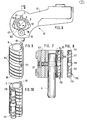
- Fig. 1
- zeigt eine Ansicht von oben eines Flügelbandteiles mit einer ersten Ausführungsform der Erfindung;
- Fig. 2
- zeigt einen Schnitt nach der Linie II-II in Fig. 1;
- Fig. 3
- zeigt eine Seitenansicht der Schraube aus Fig. 2;
- Fig. 4
- zeigt eine perspektivische Ansicht der Bandbolzenbuchse aus Fig. 1;
- Fig. 5
- zeigt eine perspektivischer Ansicht der Baugruppe aus Bandbolzenbuchse und Schraube;
- Fig. 6 bis 10
- zeigen den Fig. 1 bis 5 entsprechende Ansichten einer zweiten Ausführungsform der Erfindung;
- Fig. 1
- shows a view from above of a wing hinge part with a first embodiment of the invention;
- Fig. 2
- shows a section along the line II-II in Fig. 1;
- Fig. 3
- shows a side view of the screw of Fig. 2;
- Fig. 4
- shows a perspective view of the hinge pin bushing of Fig. 1;
- Fig. 5
- shows a perspective view of the assembly of the hinge pin bush and screw;
- 6 to 10
- show Figures 1 to 5 corresponding views of a second embodiment of the invention.
In der Zeichnung ist ein Flügelbandteil 40 eines zweiteiligen Bandes wiedergegeben,
welches zur um eine Scharnierachse A schwenkbaren Lagerung eines
Flügels an einem feststehenden Rahmen dient. Das Flügelbandteil 40 besteht
aus einem Befestigungsteil 41 und einem Scharnierteil 42, wobei das
Scharnierteil 42 oberhalb des nicht dargestellten Scharnierteils des Rahmenbandteils
angeordnet ist und den auf das Flügelbandteil 40 entfallenden Anteil
des Flügelgewichts auf das Rahmenbandteil überträgt. Die Scharnierachse A
wird von einem zylindrischen Bandbolzen 6 gebildet, der die übereinanderliegenden
Scharnierteile durchgreift und in der normalen Einbaustellung vertikal
angeordnet ist.In the drawing, a
In den dargestellten Ausführungen werden die Bandbolzenbuchse 8 bzw. der
Bandbolzen 6 nicht durch eine translatorische Bewegung verstellt, d.h. geradlinig
verschoben, sondern es findet eine Verschwenkung der Bandbolzenbuchse
8 um eine dicht außerhalb derselben gelegene, zur Scharnierachse A parallele
Schwenkachse S statt. Die Bandbolzenbuchse 8 hat in grober Annäherung
die Querschnittsgestalt eines gleichschenkligen Dreiecks mit den gleichen
Seiten 91, 92 und abgerundeten Ecken. An dem durch die Seiten 91, 92
gebildeten Scheitel sitzt außerhalb der dortigen Abrundung eine parallel zur
Scharnierachse A verlaufende Rippe 93 von im wesentlichen kreisförmigen
Querschnitt, die in einer gegen die Ausnehmung 15 offenen Längsnut 94 des
Scharnierteils 42 angeordnet ist. Durch den Mittelpunkt des Querschnitts der
Rippe 93 verläuft die zur Scharnierachse A parallel Schwenkachse S, um die
die Bandzapfenbuchse 8 in der Ausnehmung 15 in der aus Fig. 1 entnehmbaren
Weise um einen gewissen Winkel nach beiden Seiten hin verlagert werden
kann.In the illustrated embodiments, the hinge pin bushing 8 and
Hinge
Die "Grundseite" des den Querschnitt der Bandzapfenbuchse 8 bildenden angenähert
gleichschenkligen Dreiecks ist durch eine Zylinderfläche 95 gebildet,
deren Achse mit der Schwenkachse S zusammenfällt.The "base side" of the cross-section of the hinge pin bushing 8 approximates
isosceles triangle is formed by a
Der Bandbolzen 6 ist als von der Bandbolzenbuchse 8 separates Teil gezeigt,
doch versteht sich, daß er auch mit der Bandbolzenbuchse 8 einstückig sein
könnte. Dies gilt auch für die andere Ausführung nach den Fig. 6 bis 10.The
Der Verlagerungsantrieb umfaßt eine Schraube 50, die in einer auf der der
Rippe 93 gegenüberliegenden Seite in der Wandung der Ausnehmung 15 vorgesehenen
teilzylindrischen Gewindeausnehmung 109 des Scharnierteils 42
angeordnet ist. The displacement drive comprises a
Die Schraube 50 greift unmittelbar an der Bandbolzenbuchse 8 an. Wie aus
Fig. 3 erkennbar ist, besteht die Schraube 50 aus einer Spindel 105 mit einem
zylindrischen Kern 106 und einer um diesen außen herum gewendelten Rippe
107, die quasi nur einen einzigen Gewindegang darstellt, der unmittelbar in
eine Nut 104 der Bandbolzenbuchse 8 eingreift. Die seitlichen Flanken 62 der
Rippe 107 wirken mit den seitlichen Flanken 61 der Nut 104 unter Anlage zusammen
und bilden Schrägflächenpaare 60, die die Bandbolzenbuchse 8 führen.
An den Enden weist die Spindel 105 Köpfe 108 auf, die über den zylindrischen
Kern 106 radial vorspringen, eine zur Achse senkrechte stirnseitige
Endfläche aufweisen und deren Außenumfang in der gleichen Zylinderfläche
liegt wie der Außenumfang der Rippe 107. Die Spindel 105 ist in der teilzylindrischen
Ausnehmung 109 des Scharnierteils 42 angeordnet, die den gleichen
Durchmesser wie die Köpfe 108 und die Rippe 107 aufweist. Die Spindel 105
ist etwas kürzer als das Scharnierteil 42 hoch ist, so daß sie sich in diesem
nach oben oder unten um eine gewisse Strecke verlagern kann, ohne über den
Umriß des Scharnierteils 42 hervorzutreten. An beiden Köpfen 108 der Spindel
105 sind Innenmehrkanten 110 vorgesehen, so daß eine Verdrehung der
Spindel 105 und damit eine Justierung sowohl von der Oberseite als auch von
der Unterseite des Scharnierteils 42 erfolgen können.The
Bei einer Verdrehung der Spindel 105 nach recht oder links erfolgt eine Verlagerung
des unteren Teils der Bandbolzenbuchse 8 unter Verschwenkung derselben
um die Schwenkachse S in der einen oder anderen Richtung.When the
Die Wirkung könnte auch erzielt werden, wenn statt der gewendelten Rippe
107, die ja schon ziemlich steil steht, am Außenumfang des zylindrischen
Kerns 106 eine achsparallele Rippe vorgesehen wäre, die in eine entsprechende
Ausnehmung der Bandbolzenbuchse 8 eingreift. Die Verlagerung des
Bandbolzens 6 erfolgt hierbei durch bloße Verschwenkung um eine
achsparallele Achse. The effect could also be achieved if instead of the
Bei der zweiten Ausführungsform der Erfindung nach den Fig. 6 bis 10 ist wiederum
eine Spindel 115 als Schraube 50 vorgesehen, die jedoch im Gegensatz
zu der Spindel 105 mehrere Gewindegänge 117 aufweist, die in entsprechende
Nuten 114 in der teilzylindrischen Außenfläche 95 der Bandbolzenbuchse eingreifen.
In der Mitte besitzt die Spindel 115 einen verdickten Abschnitt 118,
dessen Außenumfang in dergleichen Zylinderfläche liegt wie der Außenumfang
der die Gewindegänge bildenden Rippen 117 und der in eine Umfangsausnehmung
113 der Außenfläche 95 der Bandbolzenbuchse 8 eingreift, um die
Spindel 115 gegenüber der Bandbolzenbuchse 8 in Achsrichtung zu fixieren.
Bei einer Verdrehung der Spindel 115, die durch den Eingriff eines Werkzeugs
in einen Innenmehrkant 110 an einem der beiden Enden der Spindel 115 bewerkstelligt
werden kann, erfolgt eine Verlagerung des in Fig. 6 unteren Teils
der Bandbolzenbuchse 8 nach rechts oder links, wobei sich die Spindel 115 in
der sie aufnehmenden teilzylindrischen Ausnehmung 109 an der der Rippe 93
gegenüberliegenden Seite der Ausnehmung 15 des Scharnierteils 42 abstützt.In the second embodiment of the invention according to FIGS. 6 to 10 is again
a
Claims (6)
mit mindestens einem auf der Vorderfläche des feststehenden Rahmens der Tür, des Fensters oder dergleichen befestigten Rahmenbandteil,
mit einem am Flügel der Tür, des Fensters oder dergleichen befestigten Flügelbandteil (40), das ein Scharnierteil des Rahmenbandteils mit einem Scharnierteil (42) übergreift, und in dem übergreifenden Bereich durch einen in der Einbaulage vertikalen, die Scharnierteile durchgreifenden und die Scharnierachse (A) bildenden Bandbolzen (6) mit dem Rahmenbandteil schwenkbar verbunden ist,
mit einer den Bandbolzen (6) aufnehmenden Bandbolzenbuchse (8),
mit einer in einer Ausnehmung (15) eines Scharnierteils (42) untergebrachten Bandbolzenverstellung mit einer Geradführung, an der die Bandbolzenbuchse (8) zwecks Anpassung der Lage des Flügels in der lichten Rahmenöffnung parallel zu sich selbst unter Verschwenkung um eine zur Scharnierachse (A) parallele, im Bereich ihres Umfangs gelegene Schwenkachse (5) in dem Scharnierteil (42) verlagerbar und festlegbar ist,
und mit einem von außerhalb des Scharnierteils (42) betätigbaren, eine Schraube (50) umfassenden Verlagerungsantrieb für den Bandbolzen (6),
dadurch gekennzeichnet, dass die Bandbolzenverstellung mindestens ein Paar (60) von Schrägflächen (61, 61) umfaßt, von denen jeweils die eine mit der Bandbolzen buchese (8) und jeweils die andere mit dem Scharnierteil (42) verbunden sind und die bei einem Vorschub des Verlagerungsantriebes aufeinander abgleiten und die Verstellung der Bandbolzenbuchse (8) und damit des Bandbolzens (6) in der Verstellrichtung (9) und seine Führung parallel zu sich selbst in der Ausnehmung (15) des Scharnierteils (42) mit einer einem wesentlichen Teil der Höhe des Scharnierteils (42) entsprechenden Führungslänge bewirken,
dass die Schraube (50) mit ihrer Achse (B) parallel zur Scharnierachse (A) angeordnet und
dass die Bandbolzenbuchse (8) auf der der Schwenkachse (S) bezüglich der Scharnierachse (A) gegenüberliegenden Seite mit einer Zylinderfläche (95), deren Achse mit der Schwenkachse (S) zusammenfällt, an einem als komplementäre Zylinderfläche (102) ausgebildeten Wandungsteil der Ausnehmung (15) des Scharnierteils (42) anliegt und
dass auf dem Außenumfang der die Schraube (50) bildenden Verstellspindel (105, 115) und auf der Zylinderfläche (95) der Bandbolzenbuchse (8) schraubenförmig schräg verlaufende, nach Art von Nut und Feder zusammenwirkende, die Schrägflächenpaare (60) bildenden Vorsprünge (107, 117) und Vertiefungen (104, 114) vorgesehen sind.Tape for doors, windows and the like,
with at least one frame hinge part attached to the front surface of the fixed frame of the door, window or the like,
with a wing hinge part (40) fastened to the wing of the door, the window or the like, which overlaps a hinge part of the frame hinge part with a hinge part (42), and in the overlapping area by means of a vertical one in the installed position, reaching through the hinge parts and passing through the hinge axis (A ) forming hinge pin (6) is pivotally connected to the frame hinge part,
with a hinge pin bushing (8) receiving the hinge pin (6),
with a hinge pin adjustment accommodated in a recess (15) of a hinge part (42) with a straight guide, on which the hinge pin bushing (8) for the purpose of adapting the position of the sash in the clear frame opening parallel to itself while pivoting about a parallel to the hinge axis (A) , pivot axis (5) located in the region of its circumference can be displaced and fixed in the hinge part (42),
and with a displacement drive for the hinge pin (6) which can be actuated from outside the hinge part (42) and comprises a screw (50),
characterized in that the hinge pin adjustment comprises at least one pair (60) of inclined surfaces (61, 61), one of which is connected to the hinge pin bushing (8) and the other is connected to the hinge part (42) and which is at a feed rate of the displacement drive slide on each other and the adjustment of the hinge pin bushing (8) and thus the hinge pin (6) in the adjustment direction (9) and its guidance parallel to itself in the recess (15) of the hinge part (42) with a substantial part of the height effect the corresponding guide length of the hinge part (42),
that the screw (50) with its axis (B) parallel to the hinge axis (A) and
that the hinge pin bushing (8) on the side opposite the pivot axis (S) with respect to the hinge axis (A) has a cylindrical surface (95), the axis of which coincides with the pivot axis (S), on a wall part of the recess designed as a complementary cylindrical surface (102) (15) of the hinge part (42) and
that on the outer circumference of the adjusting spindle (105, 115) forming the screw (50) and on the cylindrical surface (95) of the hinge pin bushing (8) helically sloping projections (107) which cooperate in the manner of tongue and groove and form the sloping surface pairs (60) , 117) and depressions (104, 114) are provided.
Applications Claiming Priority (3)
| Application Number | Priority Date | Filing Date | Title |
|---|---|---|---|
| DE29703324U | 1997-02-25 | ||
| DE29703324U DE29703324U1 (en) | 1997-02-25 | 1997-02-25 | Tape for doors, windows and the like |
| EP97120445A EP0860571B1 (en) | 1997-02-25 | 1997-11-21 | Hinge for doors, windows or similar |
Related Parent Applications (1)
| Application Number | Title | Priority Date | Filing Date |
|---|---|---|---|
| EP97120445A Division EP0860571B1 (en) | 1997-02-25 | 1997-11-21 | Hinge for doors, windows or similar |
Publications (3)
| Publication Number | Publication Date |
|---|---|
| EP1331339A2 true EP1331339A2 (en) | 2003-07-30 |
| EP1331339A3 EP1331339A3 (en) | 2004-05-26 |
| EP1331339B1 EP1331339B1 (en) | 2005-04-13 |
Family
ID=8036489
Family Applications (4)
| Application Number | Title | Priority Date | Filing Date |
|---|---|---|---|
| EP97120445A Expired - Lifetime EP0860571B1 (en) | 1997-02-25 | 1997-11-21 | Hinge for doors, windows or similar |
| EP03010068A Withdrawn EP1331337A3 (en) | 1997-02-25 | 1997-11-21 | Hinge for doors, windows and the like |
| EP03010070A Expired - Lifetime EP1331339B1 (en) | 1997-02-25 | 1997-11-21 | Hinge for doors, windows and the like |
| EP03010069A Expired - Lifetime EP1331338B1 (en) | 1997-02-25 | 1997-11-21 | Hinge for doors, windows and the like |
Family Applications Before (2)
| Application Number | Title | Priority Date | Filing Date |
|---|---|---|---|
| EP97120445A Expired - Lifetime EP0860571B1 (en) | 1997-02-25 | 1997-11-21 | Hinge for doors, windows or similar |
| EP03010068A Withdrawn EP1331337A3 (en) | 1997-02-25 | 1997-11-21 | Hinge for doors, windows and the like |
Family Applications After (1)
| Application Number | Title | Priority Date | Filing Date |
|---|---|---|---|
| EP03010069A Expired - Lifetime EP1331338B1 (en) | 1997-02-25 | 1997-11-21 | Hinge for doors, windows and the like |
Country Status (5)
| Country | Link |
|---|---|
| EP (4) | EP0860571B1 (en) |
| AT (3) | ATE293198T1 (en) |
| DE (4) | DE29703324U1 (en) |
| DK (2) | DK1331339T3 (en) |
| ES (2) | ES2212033T3 (en) |
Cited By (3)
| Publication number | Priority date | Publication date | Assignee | Title |
|---|---|---|---|---|
| WO2007090502A1 (en) * | 2006-02-10 | 2007-08-16 | Dr. Hahn Gmbh & Co. Kg | Hinge for doors, windows or the like |
| WO2007090487A1 (en) * | 2006-02-09 | 2007-08-16 | Dr. Hahn Gmbh & Co. Kg | Hinge for doors, windows or the like |
| GB2464950A (en) * | 2008-10-30 | 2010-05-05 | Window Fab & Fixing Supplies | Adjusting hinge |
Families Citing this family (8)
| Publication number | Priority date | Publication date | Assignee | Title |
|---|---|---|---|---|
| GB9927558D0 (en) * | 1999-11-23 | 2000-01-19 | Mila Hardware Ltd | Hinges |
| DE20207354U1 (en) * | 2002-05-08 | 2003-09-18 | Hahn Gmbh & Co Kg Dr | Tape for windows, doors or the like |
| DE20212055U1 (en) | 2002-08-05 | 2003-12-18 | Dr. Hahn Gmbh & Co. Kg | Hinge part for a hinge for doors, windows and the like. |
| GB2532904B (en) * | 2010-06-15 | 2016-07-20 | Grouphomesafe Ltd | Hinges |
| NZ706827A (en) * | 2012-11-01 | 2017-09-29 | Ciilock Eng Pty Ltd | Adjustable hinge |
| DE202013103109U1 (en) * | 2013-07-12 | 2014-10-13 | Dr. Hahn Gmbh & Co. Kg | Band lobe of a band |
| DE102015214168B3 (en) * | 2015-07-27 | 2016-07-21 | Roto Frank Ag | Adjustable hinged hinge for a window or door |
| CN106639710B (en) * | 2016-12-20 | 2018-02-06 | 广东合和建筑五金制品有限公司 | Three-dimensional adjustable insertion shaft type hinge for plastic window |
Citations (1)
| Publication number | Priority date | Publication date | Assignee | Title |
|---|---|---|---|---|
| DE4022532C1 (en) * | 1990-07-16 | 1991-12-19 | Dr. Hahn Gmbh & Co. Kg, 4050 Moenchengladbach, De |
Family Cites Families (4)
| Publication number | Priority date | Publication date | Assignee | Title |
|---|---|---|---|---|
| GB462061A (en) * | 1935-10-17 | 1937-03-02 | Triplex Foundry Ltd | Improvements in and relating to hinges for oven doors and the like |
| DE3642127A1 (en) * | 1986-12-10 | 1988-06-23 | Hahn Gmbh & Co Kg Dr | BAND FOR DOORS, WINDOWS AND THE LIKE |
| US5074609A (en) * | 1990-07-30 | 1991-12-24 | General Motors Corporation | Adjustable deck lid hinge pivot |
| AT402528B (en) * | 1992-01-31 | 1997-06-25 | Roto Frank Eisenwaren | SIDE-ADJUSTABLE LOADING TAPE |
-
1997
- 1997-02-25 DE DE29703324U patent/DE29703324U1/en not_active Expired - Lifetime
- 1997-11-21 EP EP97120445A patent/EP0860571B1/en not_active Expired - Lifetime
- 1997-11-21 DE DE59712272T patent/DE59712272D1/en not_active Expired - Fee Related
- 1997-11-21 AT AT03010069T patent/ATE293198T1/en not_active IP Right Cessation
- 1997-11-21 AT AT97120445T patent/ATE254232T1/en not_active IP Right Cessation
- 1997-11-21 EP EP03010068A patent/EP1331337A3/en not_active Withdrawn
- 1997-11-21 DK DK03010070T patent/DK1331339T3/en active
- 1997-11-21 ES ES97120445T patent/ES2212033T3/en not_active Expired - Lifetime
- 1997-11-21 EP EP03010070A patent/EP1331339B1/en not_active Expired - Lifetime
- 1997-11-21 AT AT03010070T patent/ATE293199T1/en not_active IP Right Cessation
- 1997-11-21 DE DE59710995T patent/DE59710995D1/en not_active Expired - Lifetime
- 1997-11-21 DE DE59712271T patent/DE59712271D1/en not_active Expired - Lifetime
- 1997-11-21 EP EP03010069A patent/EP1331338B1/en not_active Expired - Lifetime
- 1997-11-21 DK DK97120445T patent/DK0860571T3/en active
- 1997-11-21 ES ES03010070T patent/ES2240881T3/en not_active Expired - Lifetime
Patent Citations (1)
| Publication number | Priority date | Publication date | Assignee | Title |
|---|---|---|---|---|
| DE4022532C1 (en) * | 1990-07-16 | 1991-12-19 | Dr. Hahn Gmbh & Co. Kg, 4050 Moenchengladbach, De |
Cited By (5)
| Publication number | Priority date | Publication date | Assignee | Title |
|---|---|---|---|---|
| WO2007090487A1 (en) * | 2006-02-09 | 2007-08-16 | Dr. Hahn Gmbh & Co. Kg | Hinge for doors, windows or the like |
| CN101379265B (en) * | 2006-02-09 | 2012-05-30 | 哈恩两合公司 | Hinge for doors, windows or the like |
| WO2007090502A1 (en) * | 2006-02-10 | 2007-08-16 | Dr. Hahn Gmbh & Co. Kg | Hinge for doors, windows or the like |
| GB2464950A (en) * | 2008-10-30 | 2010-05-05 | Window Fab & Fixing Supplies | Adjusting hinge |
| GB2464950B (en) * | 2008-10-30 | 2013-09-18 | Window Fab & Fixing Supplies | Adjusting hinge |
Also Published As
| Publication number | Publication date |
|---|---|
| DK1331339T3 (en) | 2005-08-08 |
| EP1331339B1 (en) | 2005-04-13 |
| ATE293199T1 (en) | 2005-04-15 |
| DE59712272D1 (en) | 2005-05-19 |
| EP1331337A3 (en) | 2004-05-26 |
| EP1331338B1 (en) | 2005-04-13 |
| EP0860571B1 (en) | 2003-11-12 |
| ES2212033T3 (en) | 2004-07-16 |
| ES2240881T3 (en) | 2005-10-16 |
| ATE254232T1 (en) | 2003-11-15 |
| DE59710995D1 (en) | 2003-12-18 |
| DE29703324U1 (en) | 1998-07-02 |
| EP1331339A3 (en) | 2004-05-26 |
| EP1331337A2 (en) | 2003-07-30 |
| EP1331338A2 (en) | 2003-07-30 |
| DK0860571T3 (en) | 2004-03-22 |
| ATE293198T1 (en) | 2005-04-15 |
| EP1331338A3 (en) | 2004-05-26 |
| EP0860571A1 (en) | 1998-08-26 |
| DE59712271D1 (en) | 2005-05-19 |
Similar Documents
| Publication | Publication Date | Title |
|---|---|---|
| DE3642127C2 (en) | ||
| EP0285229B1 (en) | Adjustable hinge, especially for doors | |
| EP0467075B1 (en) | Hinge for doors, windows and the like and positioning element for the guiding part of such a hinge | |
| EP1331339B1 (en) | Hinge for doors, windows and the like | |
| EP1666688A2 (en) | Hinge for windows, doors and the like | |
| EP0750088B1 (en) | Hinge for doors, windows and the like | |
| EP0318422B1 (en) | Adjustable hinge, especially for doors | |
| EP1040245B1 (en) | Casement fastener closure for thick-walled doors, shutters or the like | |
| DE2211523B2 (en) | Locking element for windows or doors - has base-plate held on clamping piece in hollow profile by screw | |
| EP2949844B1 (en) | Hinge assembly for doors, windows or the like, with a clearance adjustment device | |
| EP3631131B1 (en) | Hinge strip for the pivotal connection of a wing to a frame around a hinge axis | |
| EP1563152B1 (en) | Joint hinge | |
| EP1527245A1 (en) | Hinge part for door or window hinge or the like | |
| EP1182315A1 (en) | Hinge for doors, windows or the like | |
| EP0396209B1 (en) | Hinge for doors, windows and similar | |
| EP1314844A1 (en) | Door or window hinge | |
| EP1126110B1 (en) | Locking device for doors and windows | |
| EP0804671B1 (en) | Single-axis hinge | |
| DE19816563C1 (en) | Door drive for garage | |
| EP1245770A2 (en) | Fitting for doors, windows and the like | |
| EP0340455B2 (en) | Pivot bearing for the connection of two wings of a window, door or the like | |
| EP1156181A2 (en) | Hinge for doors, windows and the like | |
| EP0524636A1 (en) | Hinge for doors, windows or the like and guiding part for the pin of such a hinge | |
| DE2949539A1 (en) | Hanger for sliding partition - has wall panel frame with roller adjustably mounted along guide rail | |
| DE2727585A1 (en) | Adjustable door or window hinge - has spindle eyes sliding relative to base plate with eccentric adjuster |
Legal Events
| Date | Code | Title | Description |
|---|---|---|---|
| PUAI | Public reference made under article 153(3) epc to a published international application that has entered the european phase |
Free format text: ORIGINAL CODE: 0009012 |
|
| 17P | Request for examination filed |
Effective date: 20030503 |
|
| AC | Divisional application: reference to earlier application |
Ref document number: 0860571 Country of ref document: EP Kind code of ref document: P |
|
| AK | Designated contracting states |
Designated state(s): AT BE CH DE DK ES FR GB IT LI NL SE |
|
| RIN1 | Information on inventor provided before grant (corrected) |
Inventor name: KLEINSCHUMACHER, REINER Inventor name: THEISSEN, HEINRICH Inventor name: SINSTEDEN, CLAUDIA Inventor name: LANGELS, STEFAN Inventor name: PILEPIC, MLADEN |
|
| PUAL | Search report despatched |
Free format text: ORIGINAL CODE: 0009013 |
|
| AK | Designated contracting states |
Kind code of ref document: A3 Designated state(s): AT BE CH DE DK ES FR GB IT LI NL SE |
|
| RIC1 | Information provided on ipc code assigned before grant |
Ipc: 7E 05D 7/04 A Ipc: 7E 05D 5/14 B |
|
| GRAP | Despatch of communication of intention to grant a patent |
Free format text: ORIGINAL CODE: EPIDOSNIGR1 |
|
| 17Q | First examination report despatched |
Effective date: 20040902 |
|
| GRAS | Grant fee paid |
Free format text: ORIGINAL CODE: EPIDOSNIGR3 |
|
| AKX | Designation fees paid |
Designated state(s): AT BE CH DE DK ES FR GB IT LI NL SE |
|
| GRAA | (expected) grant |
Free format text: ORIGINAL CODE: 0009210 |
|
| AC | Divisional application: reference to earlier application |
Ref document number: 0860571 Country of ref document: EP Kind code of ref document: P |
|
| AK | Designated contracting states |
Kind code of ref document: B1 Designated state(s): AT BE CH DE DK ES FR GB IT LI NL SE |
|
| REG | Reference to a national code |
Ref country code: GB Ref legal event code: FG4D Free format text: NOT ENGLISH |
|
| REG | Reference to a national code |
Ref country code: CH Ref legal event code: EP |
|
| REF | Corresponds to: |
Ref document number: 59712272 Country of ref document: DE Date of ref document: 20050519 Kind code of ref document: P |
|
| REG | Reference to a national code |
Ref country code: SE Ref legal event code: TRGR |
|
| REG | Reference to a national code |
Ref country code: DK Ref legal event code: T3 |
|
| REG | Reference to a national code |
Ref country code: CH Ref legal event code: NV Representative=s name: R. A. EGLI & CO. PATENTANWAELTE |
|
| GBT | Gb: translation of ep patent filed (gb section 77(6)(a)/1977) |
Effective date: 20050727 |
|
| REG | Reference to a national code |
Ref country code: ES Ref legal event code: FG2A Ref document number: 2240881 Country of ref document: ES Kind code of ref document: T3 |
|
| PLBE | No opposition filed within time limit |
Free format text: ORIGINAL CODE: 0009261 |
|
| STAA | Information on the status of an ep patent application or granted ep patent |
Free format text: STATUS: NO OPPOSITION FILED WITHIN TIME LIMIT |
|
| ET | Fr: translation filed | ||
| 26N | No opposition filed |
Effective date: 20060116 |
|
| PGFP | Annual fee paid to national office [announced via postgrant information from national office to epo] |
Ref country code: NL Payment date: 20081103 Year of fee payment: 12 Ref country code: DK Payment date: 20081114 Year of fee payment: 12 Ref country code: CH Payment date: 20081130 Year of fee payment: 12 |
|
| PGFP | Annual fee paid to national office [announced via postgrant information from national office to epo] |
Ref country code: AT Payment date: 20081112 Year of fee payment: 12 Ref country code: ES Payment date: 20081216 Year of fee payment: 12 |
|
| PGFP | Annual fee paid to national office [announced via postgrant information from national office to epo] |
Ref country code: SE Payment date: 20081107 Year of fee payment: 12 Ref country code: IT Payment date: 20081127 Year of fee payment: 12 Ref country code: BE Payment date: 20081110 Year of fee payment: 12 |
|
| PGFP | Annual fee paid to national office [announced via postgrant information from national office to epo] |
Ref country code: FR Payment date: 20081112 Year of fee payment: 12 |
|
| PGFP | Annual fee paid to national office [announced via postgrant information from national office to epo] |
Ref country code: DE Payment date: 20081130 Year of fee payment: 12 |
|
| PGFP | Annual fee paid to national office [announced via postgrant information from national office to epo] |
Ref country code: GB Payment date: 20081119 Year of fee payment: 12 |
|
| BERE | Be: lapsed |
Owner name: *HAHN G.M.B.H. & CO. K.G. Effective date: 20091130 |
|
| REG | Reference to a national code |
Ref country code: NL Ref legal event code: V1 Effective date: 20100601 |
|
| EUG | Se: european patent has lapsed | ||
| REG | Reference to a national code |
Ref country code: CH Ref legal event code: PL |
|
| REG | Reference to a national code |
Ref country code: DK Ref legal event code: EBP |
|
| GBPC | Gb: european patent ceased through non-payment of renewal fee |
Effective date: 20091121 |
|
| REG | Reference to a national code |
Ref country code: FR Ref legal event code: ST Effective date: 20100730 |
|
| PG25 | Lapsed in a contracting state [announced via postgrant information from national office to epo] |
Ref country code: AT Free format text: LAPSE BECAUSE OF NON-PAYMENT OF DUE FEES Effective date: 20091121 |
|
| PG25 | Lapsed in a contracting state [announced via postgrant information from national office to epo] |
Ref country code: LI Free format text: LAPSE BECAUSE OF NON-PAYMENT OF DUE FEES Effective date: 20091130 Ref country code: FR Free format text: LAPSE BECAUSE OF NON-PAYMENT OF DUE FEES Effective date: 20091130 Ref country code: CH Free format text: LAPSE BECAUSE OF NON-PAYMENT OF DUE FEES Effective date: 20091130 Ref country code: NL Free format text: LAPSE BECAUSE OF NON-PAYMENT OF DUE FEES Effective date: 20100601 Ref country code: BE Free format text: LAPSE BECAUSE OF NON-PAYMENT OF DUE FEES Effective date: 20091130 |
|
| PG25 | Lapsed in a contracting state [announced via postgrant information from national office to epo] |
Ref country code: DE Free format text: LAPSE BECAUSE OF NON-PAYMENT OF DUE FEES Effective date: 20100601 |
|
| PG25 | Lapsed in a contracting state [announced via postgrant information from national office to epo] |
Ref country code: GB Free format text: LAPSE BECAUSE OF NON-PAYMENT OF DUE FEES Effective date: 20091121 |
|
| PG25 | Lapsed in a contracting state [announced via postgrant information from national office to epo] |
Ref country code: DK Free format text: LAPSE BECAUSE OF NON-PAYMENT OF DUE FEES Effective date: 20091130 |
|
| PG25 | Lapsed in a contracting state [announced via postgrant information from national office to epo] |
Ref country code: IT Free format text: LAPSE BECAUSE OF NON-PAYMENT OF DUE FEES Effective date: 20091121 |
|
| REG | Reference to a national code |
Ref country code: ES Ref legal event code: FD2A Effective date: 20110404 |
|
| PG25 | Lapsed in a contracting state [announced via postgrant information from national office to epo] |
Ref country code: SE Free format text: LAPSE BECAUSE OF NON-PAYMENT OF DUE FEES Effective date: 20091122 |
|
| PG25 | Lapsed in a contracting state [announced via postgrant information from national office to epo] |
Ref country code: ES Free format text: LAPSE BECAUSE OF NON-PAYMENT OF DUE FEES Effective date: 20110322 |
|
| PG25 | Lapsed in a contracting state [announced via postgrant information from national office to epo] |
Ref country code: ES Free format text: LAPSE BECAUSE OF NON-PAYMENT OF DUE FEES Effective date: 20091122 |