EP0804671B1 - Single-axis hinge - Google Patents
Single-axis hinge Download PDFInfo
- Publication number
- EP0804671B1 EP0804671B1 EP96900317A EP96900317A EP0804671B1 EP 0804671 B1 EP0804671 B1 EP 0804671B1 EP 96900317 A EP96900317 A EP 96900317A EP 96900317 A EP96900317 A EP 96900317A EP 0804671 B1 EP0804671 B1 EP 0804671B1
- Authority
- EP
- European Patent Office
- Prior art keywords
- hinge
- straps
- single axis
- spring
- leaf
- Prior art date
- Legal status (The legal status is an assumption and is not a legal conclusion. Google has not performed a legal analysis and makes no representation as to the accuracy of the status listed.)
- Expired - Lifetime
Links
Images


Classifications
-
- E—FIXED CONSTRUCTIONS
- E05—LOCKS; KEYS; WINDOW OR DOOR FITTINGS; SAFES
- E05D—HINGES OR SUSPENSION DEVICES FOR DOORS, WINDOWS OR WINGS
- E05D15/00—Suspension arrangements for wings
- E05D15/26—Suspension arrangements for wings for folding wings
-
- E—FIXED CONSTRUCTIONS
- E05—LOCKS; KEYS; WINDOW OR DOOR FITTINGS; SAFES
- E05D—HINGES OR SUSPENSION DEVICES FOR DOORS, WINDOWS OR WINGS
- E05D5/00—Construction of single parts, e.g. the parts for attachment
- E05D5/02—Parts for attachment, e.g. flaps
- E05D5/08—Parts for attachment, e.g. flaps of cylindrical shape
-
- E—FIXED CONSTRUCTIONS
- E05—LOCKS; KEYS; WINDOW OR DOOR FITTINGS; SAFES
- E05F—DEVICES FOR MOVING WINGS INTO OPEN OR CLOSED POSITION; CHECKS FOR WINGS; WING FITTINGS NOT OTHERWISE PROVIDED FOR, CONCERNED WITH THE FUNCTIONING OF THE WING
- E05F1/00—Closers or openers for wings, not otherwise provided for in this subclass
- E05F1/08—Closers or openers for wings, not otherwise provided for in this subclass spring-actuated, e.g. for horizontally sliding wings
- E05F1/10—Closers or openers for wings, not otherwise provided for in this subclass spring-actuated, e.g. for horizontally sliding wings for swinging wings, e.g. counterbalance
- E05F1/12—Mechanisms in the shape of hinges or pivots, operated by springs
- E05F1/1284—Mechanisms in the shape of hinges or pivots, operated by springs with a leaf or similar spring
-
- E—FIXED CONSTRUCTIONS
- E05—LOCKS; KEYS; WINDOW OR DOOR FITTINGS; SAFES
- E05D—HINGES OR SUSPENSION DEVICES FOR DOORS, WINDOWS OR WINGS
- E05D7/00—Hinges or pivots of special construction
- E05D7/04—Hinges adjustable relative to the wing or the frame
- E05D7/0407—Hinges adjustable relative to the wing or the frame the hinges having two or more pins and being specially adapted for cabinets or furniture
-
- E—FIXED CONSTRUCTIONS
- E05—LOCKS; KEYS; WINDOW OR DOOR FITTINGS; SAFES
- E05Y—INDEXING SCHEME ASSOCIATED WITH SUBCLASSES E05D AND E05F, RELATING TO CONSTRUCTION ELEMENTS, ELECTRIC CONTROL, POWER SUPPLY, POWER SIGNAL OR TRANSMISSION, USER INTERFACES, MOUNTING OR COUPLING, DETAILS, ACCESSORIES, AUXILIARY OPERATIONS NOT OTHERWISE PROVIDED FOR, APPLICATION THEREOF
- E05Y2900/00—Application of doors, windows, wings or fittings thereof
- E05Y2900/20—Application of doors, windows, wings or fittings thereof for furniture, e.g. cabinets
Definitions
- the invention relates to a single-axis hinge, in particular for folding doors with several door leaf elements, according to Preamble of claim 1.
- Single-axis hinges of this type are needed to, for example, at Folding doors the individual door leaf elements like an accordion to be able to lock and open.
- the invention is therefore based on the object of a single-axis hinge of the type mentioned at the beginning, where symmetrical forces on neighboring door leaf elements are exercised, with the door wings in the extended Keep closed position aligned.
- a spring acts on both hinge tabs under tension such that this in a closed position Folding door at a mutual angle of 180 ° in a first stable position.
- Such one Single-axis hinge holds the door leaf elements of a folding door in their extended position, which causes the door leaves to slide in held on a level without e.g. under can move the influence of pressure fluctuations in the room.
- Such a folding door is therefore kept stable without rattling of the door leaf elements can occur.
- the spring both hinge tabs in the extended position of the door leaf elements, that is in the closed position of the folding door, against you the angular position the hinge tab to each other at an opening angle of 180 ° restricting stop presses.
- a such stop serves to prevent the hinge take an opening position beyond 180 ° can.
- the spring can also open the hinge tab the folding door at a mutual angle of Hinge tabs of approx. 0 ° in a second stable position hold so that the door leaf elements also in their Open position can be held together compactly.
- the spring exercises an intermediate position between 0 and 180 ° Restoring force on the door leaf elements and relieved the actuation of a folding door towards the End positions.
- the axis of rotation of the single-axis joint is related to the Swivel range of the hinge flaps on the inside of the Hinge tabs arranged.
- the arrangement of the axis of rotation on the inside of the hinge tab allows the Hinge tabs and thus the door leaf elements closed by 180 ° swivel.
- the spring is related to the swivel range of the hinge flaps also on the inside of the hinge tab arranged.
- a spring arranged in this way is reached their widest spread position at an angle of 90 ° between the hinge tabs.
- a dead center of the force acting on the hinge lobe achieved because the symmetrical forces of the spring mutually pick up and no torque on the hinge tabs produce.
- the hinge tabs are pushed apart, while after passing dead center the hinge tabs compressed due to the spring force will.
- a leaf spring has that Advantage that the force application point on the hinge tab can be distributed over the entire hinge width.
- the projections on the hinge tabs are provided one each parallel to the axis of rotation of the single-axis joint to form a running groove. In this groove can accordingly engage shaped ends of a leaf spring and so that the projections reach behind.
- the groove is interrupted by at least one stiffening rib is.
- the leaf spring is corresponding recessed to allow penetration of the stiffening ribs to enable.
- the hinge tabs can be close to the axis of rotation of the Have lateral projections arranged in a single-axis joint, that hook into the hinge pots.
- the side Protrusions serve to better support the hinge tabs in the hinge cups, so that such single-axis hinges can absorb higher forces.
- the Leaf spring assembly consists of two leaf springs, wherein an outer leaf spring at least partially form-fitting sits on an inner leaf spring.
- the double arrangement a leaf spring has the advantage that when used the tensile and compressive stress in each one Leaf springs are lower, resulting in a longer service life the spring is reachable.
- the single-axis hinge shown in Fig. 1 for at least two door leaf elements 3 existing folding doors 2, there from two hinge tabs 4.6, which are connected via a single-axis joint 5 are hinged together.
- the hinge cloth 4,6 are in hinge pots 8,10 with a screw 11 attached, the hinge tabs 4.6 in the hinge cups 8.10 are adjustable laterally, which makes the width the joint remaining between the door leaf elements 3 9 may also only be adjustable on one side.
- the hinge cloth 4,6 have an elongated hole 15 for the passage the screw 11, the slot being orthogonal runs to the axis of rotation of the single-axis joint 5 and thus allows depth adjustment.
- the hinge tabs 4.6 are at the bottom of the slot 15 and provided with teeth 17 on both sides of the elongated hole, with a corresponding toothing 19 of the hinge cups 8,10 is engaged and thus the hinge tab 4.6 against slipping out of the hinge cups 8.10 saves.
- the hinge pots 8, 10 are in the door leaf elements 3 arranged sunk and with the help of a mounting plate 28 secured against twisting on the door leaf element 3 attached with screws 11.
- the uniaxial joint 5 is from the fork part 30 of the hinge flap 4, the roller part 32 of the hinge flap 6 and the hinge pin 34 formed in the axis of rotation of the single-axis joint 5 through the fork part 30 and that Roller part 32 is passed.
- the fork part 30 and the roller part 32 of the hinge flap 4,6 stand from the plate-shaped part of the hinge lobe 4.6 from an angle of approx. 70 to 75 °.
- a cam-shaped Projection 14 or 16 formed on by a groove 18 or 20 is formed. They can around the ledge Engage ends of a leaf spring 12 in the groove 18 or 20 and one with respect to the axis of rotation of the single-axis joint 5 Transfer symmetrical force to both hinge tabs 4.6.
- the projections 14, 16 are rounded and the outer contour the ends of the leaf spring 12 is the outer contour of the Adjusted projections 14,16 so that a relative movement Hinge actuation between the leaf spring 12 and the Projections 14, 16 is possible.
- Both hinge tabs 4, 6 have in their longitudinal center plane each have a stiffening rib 22 that the groove projection combination 14,16,18,20 stabilized and on the other hand forms a position lock for the leaf spring 12.
- the Stiffening ribs 22 are orthogonal to the axis of rotation of the single-axis joint 5.
- the leaf spring 12, 12a, 12b is on their ends, which overlap the projections 14, 16 with a Provide recess 13 which the stiffening ribs 22nd is adjusted.
- the projection is from the axis of rotation of the single-axis joint 5 at an angle of approx. 45 °. In the 180 ° position the projections form between the hinge tabs 4, 6 14.16 therefore an angle of approximately 90 °.
- the leaf spring 12 presses the two projections 14, 16 in this position 180 ° towards each other, so that the hinge tab 4.6 below Preload are kept in the stretched position. You can the two hinge tabs 4.6 on one stop forming end face not shown in the drawings butt so that the hinge tabs 4.6 cannot be moved beyond 180 °.
- hinge tabs 4.6 are laterally on both sides Projections 24 are molded into the corresponding recesses 23 of the hinge cups 8, 10 engage and thus additionally hook into the hinge cups 8,10.
- the under hook the hinge tab 6,8 in the hinge cups increases the resilience of the single-axis hinge.
- Fig. 8 shows the cross-sectional shape of the leaf spring 12, the is designed essentially ⁇ -shaped and with their free Ends adapted to the radius of curvature of the projections 14, 16 is.
- leaf spring arrangement 10 shows a leaf spring arrangement with two leaf springs 12a, 12b, the one another in terms of their dimensions are coordinated that they are put on top of each other can be and together on the cam-like projections 14, 16 of the single-axis hinge can be clamped can.
- Such a leaf spring arrangement with two leaf springs 12a, 12b has the advantage of being on the individual To reduce leaf spring acting tensile and compressive stresses which increases the service life of the leaf spring can.
- FIG. 11 shows a further leaf spring arrangement with two Leaf springs 12a, 12b, in which the outer leaf spring 12a inner leaf spring 12b does not completely enclose.
- a such leaf spring is cheaper to manufacture and easier to assemble.
Landscapes
- Engineering & Computer Science (AREA)
- Mechanical Engineering (AREA)
- Hinges (AREA)
- Closing And Opening Devices For Wings, And Checks For Wings (AREA)
- Glass Compositions (AREA)
- Hinge Accessories (AREA)
- Extensible Doors And Revolving Doors (AREA)
- Transition And Organic Metals Composition Catalysts For Addition Polymerization (AREA)
- Piezo-Electric Or Mechanical Vibrators, Or Delay Or Filter Circuits (AREA)
- Dry Shavers And Clippers (AREA)
Abstract
Description
Die Erfindung betrifft ein Einachsscharnier, insbesondere für Falttüren mit mehreren Türflügelelementen, nach dem Oberbegriff des Anspruchs 1.The invention relates to a single-axis hinge, in particular for folding doors with several door leaf elements, according to Preamble of claim 1.
Derartige Einachsscharniere, wie insbesondere in DE-A-31 04 275 beschrieben, werden benötigt, um beispielsweise bei Falttüren die einzelnen Türflügelelemente ziehharmonikaartig verschließen und öffnen zu können.Single-axis hinges of this type, as in particular in DE-A-31 04 275 described are needed to, for example, at Folding doors the individual door leaf elements like an accordion to be able to lock and open.
Diese Einachsscharniere können aufgrund der Scharniertopfbefestigung hohe Drehmomente und Kräfte aufnehmen und bieten zusätzlich die Möglichkeit der Verstellung der Fugenbreite zwischen den einzelnen Türflügeln. Nachteilig ist bei dem bekannten Einachsscharnier, daß die einzelnen Türflügel relativ zueinander nicht fixiert werden, so daß die Türflügel in ihrer Strecklänge häufig nicht exakt in einer Ebene verlaufen, und daß je nach Winkelstellung des Scharniers z.T. erhebliche Kräfte aufgewendet werden müssen, um die Türflügelelemente der Falttüre beim Öffnen weiter zusammenzudrücken. These single-axis hinges can due to the hinge cup attachment absorb high torques and forces and also offer the possibility of adjusting the Joint width between the individual door leaves. Disadvantageous is in the known single-axis hinge that the individual Door leaves can not be fixed relative to each other, so that the length of the door wing is often not exactly in one plane, and that depending on the angular position of the Hinge partly considerable forces have to be used around the door leaf elements of the folding door when opening continue to squeeze.
Der Erfindung liegt daher die Aufgabe zugrunde, ein Einachsscharnier der eingangs genannten Art weiterzubilden, bei dem symmetrische Kräfte auf benachbarte Türflügelelemente ausgeübt werden, wobei die Türflügel in der gestreckten Schließstellung ausgerichtet gehalten werden.The invention is therefore based on the object of a single-axis hinge of the type mentioned at the beginning, where symmetrical forces on neighboring door leaf elements are exercised, with the door wings in the extended Keep closed position aligned.
Zur Lösung dieser Aufgabe dienen die Merkmale des Anspruchs 1.The features of the claim serve to solve this problem 1.
Eine Feder wirkt unter Vorspannung auf beide Scharnierlappen derart ein, daß diese in einer Schließstellung der Falttüre unter einem gegenseitigen Winkel von 180° in einer ersten stabilen Lage gehalten werden. Ein solches Einachsscharnier hält die Türflügelelemente einer Falttüre in ihrer gestreckten Position, wodurch die Türflügel in einer Ebene gehalten werden, ohne daß sie sich z.B. unter dem Einfluß von Druckschwankungen im Raum bewegen können. Eine solche Falttüre wird daher stabil gehalten, ohne daß ein Klappern der Türflügelelemente auftreten kann.A spring acts on both hinge tabs under tension such that this in a closed position Folding door at a mutual angle of 180 ° in a first stable position. Such one Single-axis hinge holds the door leaf elements of a folding door in their extended position, which causes the door leaves to slide in held on a level without e.g. under can move the influence of pressure fluctuations in the room. Such a folding door is therefore kept stable without rattling of the door leaf elements can occur.
Dabei kann vorgesehen sein, daß die Feder beide Scharnierlappen in der gestreckten Lage der Türflügelelemente, also in der Schließstellung der Falttüre, gegen einen die Winkelstellung der Scharnierlappen zueinander auf einen Öffnungswinkel von 180° beschränkenden Anschlag drückt. Ein solcher Anschlag dient dazu, zu verhindern, daß das Scharnier eine Öffnungsstellung über 180° hinaus einnehmen kann.It can be provided that the spring both hinge tabs in the extended position of the door leaf elements, that is in the closed position of the folding door, against you the angular position the hinge tab to each other at an opening angle of 180 ° restricting stop presses. A such stop serves to prevent the hinge take an opening position beyond 180 ° can.
Die Feder kann die Scharnierlappen auch in einer Öffnungsstellung der Falttür unter einem gegenseitigen Winkel der Scharnierlappen von ca. 0° in einer zweiten stabilen Lage halten, so daß die Türflügelelemente auch in ihrer Öffnungsstellung kompakt zusammengehalten werden. In den Zwischenstellungen zwischen 0 und 180° übt die Feder eine Rückstellkraft auf die Türflügelelemente aus und erleichtert die Betätigung einer Falttüre in Richtung auf die Endpositionen.The spring can also open the hinge tab the folding door at a mutual angle of Hinge tabs of approx. 0 ° in a second stable position hold so that the door leaf elements also in their Open position can be held together compactly. In the The spring exercises an intermediate position between 0 and 180 ° Restoring force on the door leaf elements and relieved the actuation of a folding door towards the End positions.
Die Drehachse des Einachsgelenkes ist bezogen auf den Schwenkbereich der Scharnierlappen auf der Innenseite der Scharnierlappen angeordnet. Die Anordnung der Drehachse auf der Innenseite der Scharnierlappen ermöglicht es, die Scharnierlappen und damit die Türflügelelemente um 180° zu verschwenken.The axis of rotation of the single-axis joint is related to the Swivel range of the hinge flaps on the inside of the Hinge tabs arranged. The arrangement of the axis of rotation on the inside of the hinge tab allows the Hinge tabs and thus the door leaf elements closed by 180 ° swivel.
Die Feder ist bezogen auf den Schwenkbereich der Scharnierlappen ebenfalls auf der Innenseite der Scharnierlappen angeordnet. Eine derartig angeordnete Feder erreicht ihre weiteste Spreizstellung bei einem Winkel von 90° zwischen den Scharnierlappen. In dieser Lage ist bezüglich der Krafteinwirkung auf die Scharnierlappen ein Totpunkt erreicht, da die symmetrischen Kräfte der Feder sich gegenseitig aufheben und kein Drehmoment auf die Scharnierlappen erzeugen. Vor Erreichen dieses Totpunktes aus der Öffnungsstellung heraus werden die Scharnierlappen auseinandergedrückt, während nach dem Überschreiten des Totpunktes die Scharnierlappen aufgrund der Federkraft zusammengedrückt werden.The spring is related to the swivel range of the hinge flaps also on the inside of the hinge tab arranged. A spring arranged in this way is reached their widest spread position at an angle of 90 ° between the hinge tabs. In this situation is regarding a dead center of the force acting on the hinge lobe achieved because the symmetrical forces of the spring mutually pick up and no torque on the hinge tabs produce. Before reaching this dead center from the The hinge tabs are pushed apart, while after passing dead center the hinge tabs compressed due to the spring force will.
Vorzugsweise ist vorgesehen, daß die Feder aus einer Blattfederanordnung mit mindestens einer Blattfeder besteht, die beide Scharnierlappen an jeweils mindestens einem Vorsprung hintergreift. Eine Blattfeder hat den Vorteil, daß der Kraftangriffspunkt an den Scharnierlappen über die gesamte Scharnierbreite verteilt werden kann.It is preferably provided that the spring from a Leaf spring arrangement with at least one leaf spring, the two hinge tabs on each at least engages behind a lead. A leaf spring has that Advantage that the force application point on the hinge tab can be distributed over the entire hinge width.
Es ist vorgesehen, die Vorsprünge an den Scharnierlappen von jeweils einer parallel zur Drehachse des Einachsgelenkes verlaufenden Nut zu bilden. In diese Nut können entsprechend geformte Enden einer Blattfeder eingreifen und damit die Vorsprünge hintergreifen.The projections on the hinge tabs are provided one each parallel to the axis of rotation of the single-axis joint to form a running groove. In this groove can accordingly engage shaped ends of a leaf spring and so that the projections reach behind.
Zur Aufnahme von hohen Kräften kann dabei vorgesehen sein, daß die Nut von mindestens einer Versteifungsrippe unterbrochen ist. In diesem Fall ist die Blattfeder entsprechend ausgespart, um einen Durchgriff der Versteifungsrippen zu ermöglichen.To absorb high forces, it can be provided that that the groove is interrupted by at least one stiffening rib is. In this case the leaf spring is corresponding recessed to allow penetration of the stiffening ribs to enable.
Die Scharnierlappen können in der Nähe der Drehachse des Einachsgelenkes angeordnete seitliche Vorsprünge aufweisen, die in den Scharniertöpfen unterhaken. Die seitlichen Vorsprünge dienen zur besseren Abstützung der Scharnierlappen in den Scharniertöpfen, so daß derartige Einachsscharniere höhere Kräfte aufnehmen können.The hinge tabs can be close to the axis of rotation of the Have lateral projections arranged in a single-axis joint, that hook into the hinge pots. The side Protrusions serve to better support the hinge tabs in the hinge cups, so that such single-axis hinges can absorb higher forces.
Bei einem Ausführungsbeispiel ist vorgesehen, daß die Blattfederanordnung aus zwei Blattfedern besteht, wobei eine äußere Blattfeder zumindest teilweise formschlüssig auf einer inneren Blattfeder sitzt. Die Doppelanordnung einer Blattfeder hat den Vorteil, daß bei der Gebrauchsbelastung die Zug- und Druckspannung in jeder einzelnen Blattfeder niedriger sind, wodurch eine höhere Standzeit der Feder erreichbar ist.In one embodiment it is provided that the Leaf spring assembly consists of two leaf springs, wherein an outer leaf spring at least partially form-fitting sits on an inner leaf spring. The double arrangement a leaf spring has the advantage that when used the tensile and compressive stress in each one Leaf springs are lower, resulting in a longer service life the spring is reachable.
An den Scharniertöpfen können zwischen den Stirnseiten der Türflügelelemente dehnbare Dichtungen angeordnet sein, die es ermöglichen, den Scharnierbereich abzudichten oder auch die gesamte Fuge zwischen zwei Türflügelelementen der Falttür. You can use the hinge cups between the front of the Door leaf elements can be arranged expandable seals make it possible to seal the hinge area or also the entire joint between two door leaf elements of the Folding door.
Im folgenden wird unter Bezugnahme auf die Zeichnungen ein Ausführungsbeispiel näher erläutert.The following is a reference to the drawings Embodiment explained in more detail.
Es zeigen:
- Fig. 1
- Eine Draufsicht auf ein zwei Türflügelelemente verbindendes Einachsscharnier,
- Fig. 2
- einen Schnitt entlang der Linie II-II in Fig. 1,
- Fig. 3
- eine Draufsicht auf einen Scharnierlappen mit Gabelteil,
- Fig. 4
- einen Schnitt entlang der Linie IV-IV in Fig. 3,
- Fig. 5
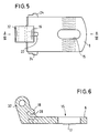
- eine Draufsicht auf den Scharnierlappen mit Rollenteil,
- Fig. 6
- einen Schnitt entlang der Linie VI-VI in Fig. 5,
- Fig. 7
- einen Schnitt durch einen Scharniertopf,
- Fig. 8
- eine Draufsicht auf eine Blattfeder,
- Fig. 9
- eine Seitenansicht der Blattfeder gemäß Fig. 8,
- Fig. 10
- eine Draufsicht auf eine Blattfederanordnung mit zwei Blattfedern, und
- Fig. 11
- eine Draufsicht auf eine weitere Blattfederanordnung.
- Fig. 1
- A top view of a single-axis hinge connecting two door leaf elements,
- Fig. 2
- 2 shows a section along the line II-II in FIG. 1,
- Fig. 3
- a top view of a hinge tab with fork part,
- Fig. 4
- 4 shows a section along the line IV-IV in FIG. 3,
- Fig. 5
- a plan view of the hinge tab with roller part,
- Fig. 6
- 4 shows a section along the line VI-VI in FIG. 5,
- Fig. 7
- a section through a hinge cup,
- Fig. 8
- a top view of a leaf spring,
- Fig. 9
- 8 shows a side view of the leaf spring according to FIG. 8,
- Fig. 10
- a plan view of a leaf spring arrangement with two leaf springs, and
- Fig. 11
- a plan view of a further leaf spring arrangement.
Das in Fig. 1 gezeigte Einachsscharnier für aus mindestens
zwei Türflügelelementen 3 bestehenden Falttüren 2, besteht
aus zwei Scharnierlappen 4,6, die über ein Einachsgelenk
5 gelenkig miteinander verbunden sind. Die Scharnierlappen
4,6 sind in Scharniertöpfen 8,10 mit einer Schraube 11
befestigt, wobei die Scharnierlappen 4,6 in den Scharniertöpfen
8,10 seitlich einstellbar sind, wodurch die Weite
der zwischen den Türflügelelementen 3 verbleibenden Fuge
9 ggf. auch nur einseitig einstellbar ist. Die Scharnierlappen
4,6 weisen hierzu ein Langloch 15 für den Durchtritt
der Schraube 11 auf, wobei das Langloch orthogonal
zur Drehachse des Einachsgelenkes 5 verläuft und damit
eine Tiefeneinstellung ermöglicht. Die Scharnierlappen 4,6
sind auf ihrer Unterseite in Höhe des Langlochs 15 und
beiderseits des Langlochs mit einer Verzahnung 17 versehen,
die mit einer entsprechenden Verzahnung 19 der Scharniertöpfe
8,10 im Eingriff ist und damit die Scharnierlappen
4,6 gegen ein Herausrutschen aus den Scharniertöpfen
8,10 sichert.The single-axis hinge shown in Fig. 1 for at least
two
Die Scharniertöpfe 8,10 sind in den Türflügelelementen 3
versenkt angeordnet und mit Hilfe einer Befestigungsplatte
28 gegen Verdrehen gesichert auf dem Türflügelelement 3
mit Schrauben 11 befestigt.The
Das Einachsgelenk 5 wird von dem Gabelteil 30 des Scharnierlappens
4, dem Rollenteil 32 des Scharnierlappens 6
sowie dem Scharnierbolzen 34 gebildet, der in der Drehachse
des Einachsgelenkes 5 durch das Gabelteil 30 und das
Rollenteil 32 hindurchgeführt ist.The uniaxial joint 5 is from the
Das Gabelteil 30 und das Rollenteil 32 der Scharnierlappen
4,6 stehen von dem plattenförmigen Teil der Scharnierlappen
4,6 unter einem Winkel von ca. 70 bis 75° ab. The
An dem Gabelteil 30 und an dem Rollenteil 32 ist, wie am
besten aus den Fign. 4 und 6 ersichtlich ist, ein nocken-förmiger
Vorsprung 14 bzw. 16 angeformt, der von einer Nut
18 bzw. 20 gebildet ist. Um den Vorsprung herum können die
Enden einer Blattfeder 12 in die Nut 18 bzw. 20 eingreifen
und eine in bezug auf die Drehachse des Einachsgelenkes 5
symmetrische Kraft auf beide Scharnierlappen 4,6 übertragen.
Die Vorsprünge 14,16 sind gerundet und die Außenkontur
der Enden der Blattfeder 12 ist der Außenkontur der
Vorsprünge 14,16 angepaßt, so daß eine Relativbewegung bei
Scharnierbetätigung zwischen der Blattfeder 12 und den
Vorsprüngen 14,16 möglich ist.On the
Beide Scharnierlappen 4,6 weisen in ihrer Längsmittelebene
jeweils eine Versteifungsrippe 22 auf, die die Nut Vorsprungkombination
14,16,18,20 stabilisiert und andererseits
eine Lagesicherung für die Blattfeder 12 bildet. Die
Versteifungsrippen 22 verlaufen orthogonal zur Drehachse
des Einachsgelenkes 5. Die Blattfeder 12,12a,12b ist an
ihren, die Vorsprünge 14,16 übergreifenden Enden mit einer
Aussparung 13 versehen, die den Versteifungsrippen 22
angepaßt ist.Both
Der Vorsprung steht von der Drehachse des Einachsgelenkes
5 unter einem Winkel von ca. 45° ab. In der 180°-Stellung
zwischen den Scharnierlappen 4,6 bilden die Vorsprünge
14,16 daher einen Winkel von ca. 90°. Die Blattfeder 12
drückt die beiden Vorsprünge 14,16 in dieser Stellung von
180° aufeinander zu, so daß die Scharnierlappen 4,6 unter
Vorspannung in der Strecklage gehalten werden. Dabei können
die beiden Scharnierlappen 4,6 an einer einen Anschlag
bildenden in den Zeichnungen nicht dargestellten Stirnfläche
aneinanderstoßen, so daß die Scharnierlappen 4,6
nicht über 180° hinaus bewegt werden können. The projection is from the axis of rotation of the single-axis joint
5 at an angle of approx. 45 °. In the 180 ° position
the projections form between the
Beim Schließen des Einachsscharniers d.h. beim Öffnen
einer Falttüre 2 wird, wie am besten aus Fig. 2 ersichtlich,
die Blattfeder 12,12a,12b zunächst gespreizt, wodurch
eine Rückstellkraft auf die Scharnierlappen 4,6
einwirkt. Bei einer Winkelstellung von 90° der Türflügelelemente
3 kompensieren sich die auf die Scharnierlappen
4,6 ausgeübten Federkräfte, da die Vorsprünge 14,16 einen
Winkel von 180° relativ zueinander einnehmen. In dieser
Stellung hat das Einachsscharnier bezüglich der Federkräfte
einen Totpunkt, der allerdings aufgrund der Winkelstellung
der Türflügelelemente 3 ohne großen Kraftaufwand
überwunden werden kann. Nach Überschreitung dieses Totpunktes
übt die Blattfeder 12 ein Drehmoment auf die Vorsprünge
14,16 aus, daß ein Schließen des Einachsscharniers
in die 0°-Stellung begünstigt. Die Türflügelelemente 3
werden in der Schließstellung wie in der Offenstellung der
Falttüre 2 stabil gehalten, wobei in den Zwischenstellungen
von der Blattfeder 12 Hilfskräfte auf die Türflügelelemente
3 ausgeübt werden, die ein Öffnen oder Schließen
der Falttüre 2 erleichtern.When closing the single axis hinge i.e. When opening
a
An den Scharnierlappen 4,6 sind seitlich auf beiden Seiten
Vorsprünge 24 angeformt, die in entsprechende Aussparungen
23 der Scharniertöpfe 8,10 eingreifen und sich somit zusätzlich
in den Scharniertöpfen 8,10 unterhaken. Das Unterhaken
der Scharnierlappen 6,8 in den Scharniertöpfen
erhöht die Belastbarkeit des Einachsscharniers.On the hinge tabs 4.6 are laterally on both
Fig. 8 zeigt die Querschnittsform der Blattfeder 12, die
im wesentlichen Ω-förmig gestaltet ist und mit ihren freien
Enden dem Rundungsradius der Vorsprünge 14,16 angepaßt
ist. Fig. 8 shows the cross-sectional shape of the
Fig. 10 zeigt eine Blattfederanordnung mit zwei Blattfedern
12a,12b, die hinsichtlich ihrer Abmessungen so aufeinander
abgestimmt sind, daß sie übereinandergestülpt
werden können und gemeinsam auf die nockenartigen Vorsprünge
14,16 des Einachsscharniers aufgeklemmt werden
können. Eine derartige Blattfederanordnung mit zwei Blattfedern
12a,12b hat den Vorteil, die auf die einzelne
Blattfeder einwirkenden Zug- und Druckspannungen zu verringern,
wodurch die Standzeit der Blattfeder erhöht werden
kann.10 shows a leaf spring arrangement with two
Fig. 11 zeigt eine weitere Blattfederanordnung mit zwei
Blattfedern 12a,12b, bei der die äußere Blattfeder 12a die
innere Blattfeder 12b nicht vollständig umschließt. Eine
solche Blattfeder ist preiswerter herzustellen und einfacher
zu montieren.11 shows a further leaf spring arrangement with two
Claims (12)
- A single axis hinge, in particular for folding doors (2) having multiple leaf elements (3), comprising at least two hinge straps (4, 6) hingedly connected through a single axis hinge (5) and hinge pots (8, 10) to be fastened in the leaf elements (3), in which hinge pots the hinge straps (4, 6) are fastened adjustably by means of a respective plate-shaped member, and further comprising a spring (12) which, under the action of a biasing force, holds both hinge straps (4, 6) in a first stable state, when the leaf elements (3) are in a closed position, where the angle formed by the hinge straps is 180° with respect to the stretched position of both hinge straps (4, 6) and the two leaf elements connected through the hinge, said stretched position extending in one plane, and which, in the open position, holds the hinge straps in a second stable state at a distance under a mutual angle of 0°,
characterized in
the pivot axis of the single axis hinge (5) is spaced from the plate-shaped members with respect to the pivot range of the hinge straps (4, 6) and that the spring (12), with respect to the pivot range of the hinge straps (4, 6), engages the hinge straps (4, 6) on the side of the hinge straps (4, 6) facing towards the pivot axis. - The single axis hinge of claim 1, characterized in that the spring (12) urges both hinge straps (4, 6) against a stop limiting the opening angle to 180°.
- The single axis hinge of claim 1 or 2, characterized in that, in the open position of the leaf elements (3), the spring (12) holds both hinge straps (4, 6) in a second stable state at a distance under a mutual angle of approximately 0°.
- The single axis hinge of one of claims 1 to 3, characterized in that the pivot axis of the single axis hinge (5) is arranged on the inside of the hinge straps (4, 6) with regard to the pivot range of the hinge straps (4, 6).
- The single axis hinge of one of claims 1 to 4, characterized in that the spring 12, is arranged on the inside of the hinge straps (4, 6) with regard to the pivot range of the hinge straps (4, 6).
- The single axis hinge of one of claims 1 to 5, characterized in that the spring (12) is a leaf spring arrangement with at least one leaf spring (12, 12a, 12b) engaging behind both hinge straps (4, 6) at at least one projection (14, 16).
- The single axis hinge of claim 6, characterized in that the projections (14, 16) on the hinge straps (4, 6) are formed by a respective groove (18, 20) extending in parallel to the pivot axis of the single axis hinge (5).
- The single axis hinge of claim 7, characterized in that the groove (18, 20) is interrupted by at least one reinforcing rib (22).
- The single axis hinge of one of claims 1 to 8, characterized in that the hinge straps (4, 6) have lateral projections (24) near the pivot axis of the single axis hinge (5) that catch in the hinge pots (8, 10) from below.
- The single axis hinge of one of claims 1 to 9, characterized in that the hinge straps (4, 6) and the hinge pots (8, 10) receiving the hinge straps (4, 6) have mutually adapted and facing toothed surfaces (17, 19) that are in engagement with each other.
- The single axis hinge of one of claims 6 to 10, characterized in that the leaf spring arrangement comprises two leaf springs, an outer leaf spring (12a) being set, at least partly, in a form fitting manner onto an inner leaf spring (12b).
- The single axis hinge of one of claims 1 to 11, characterized in that the hinge pots (8, 10) have the end face directed towards the gap (9) between the leaf elements (3) provided with a groove (25) for receiving an expandable sealing (26) in the gap (9).
Applications Claiming Priority (3)
| Application Number | Priority Date | Filing Date | Title |
|---|---|---|---|
| DE29500886U | 1995-01-20 | ||
| DE29500886U DE29500886U1 (en) | 1995-01-20 | 1995-01-20 | Single axis hinge |
| PCT/EP1996/000114 WO1996022441A1 (en) | 1995-01-20 | 1996-01-12 | Single-axis hinge |
Publications (2)
| Publication Number | Publication Date |
|---|---|
| EP0804671A1 EP0804671A1 (en) | 1997-11-05 |
| EP0804671B1 true EP0804671B1 (en) | 1998-12-02 |
Family
ID=8002747
Family Applications (1)
| Application Number | Title | Priority Date | Filing Date |
|---|---|---|---|
| EP96900317A Expired - Lifetime EP0804671B1 (en) | 1995-01-20 | 1996-01-12 | Single-axis hinge |
Country Status (4)
| Country | Link |
|---|---|
| EP (1) | EP0804671B1 (en) |
| AT (1) | ATE174099T1 (en) |
| DE (2) | DE29500886U1 (en) |
| WO (1) | WO1996022441A1 (en) |
Families Citing this family (4)
| Publication number | Priority date | Publication date | Assignee | Title |
|---|---|---|---|---|
| IT1292005B1 (en) * | 1997-05-27 | 1999-01-25 | Aldo Mignani | HINGE CONNECTION DEVICE ESPECIALLY FOR CABINET DOORS |
| ES2166255B1 (en) * | 1999-04-13 | 2003-01-01 | Imaginacion Organizada S L | FLAT HINGE FOR FOLDING DOOR. |
| DE102011115536A1 (en) * | 2011-08-17 | 2013-02-21 | Weinor Gmbh & Co. Kg | Schiebefalttürsystem |
| KR102481264B1 (en) * | 2018-01-04 | 2022-12-26 | 삼성전자주식회사 | Display appartus and display module hinge assembly |
Family Cites Families (6)
| Publication number | Priority date | Publication date | Assignee | Title |
|---|---|---|---|---|
| DE2952246A1 (en) * | 1979-12-24 | 1981-07-30 | Hetal-Werke Franz Hettich Gmbh & Co, 7297 Alpirsbach | Furniture door or flap hinge - has sloped double layered leaf spring shank section locking onto guide rod |
| DE3104275A1 (en) * | 1981-02-07 | 1982-08-19 | Huwil-Werke GmbH Möbelschloß- und Beschlagfabriken, 5207 Ruppichteroth | Hinge, especially for folding doors |
| GB2137691B (en) * | 1983-01-24 | 1986-07-16 | Dantville Limited | Folding element |
| JPH022978U (en) * | 1988-06-10 | 1990-01-10 | ||
| DE9105891U1 (en) * | 1991-05-13 | 1991-08-14 | Bockisch, Karlheinz, 3008 Garbsen | Folding gate |
| DE4035199C2 (en) * | 1990-11-06 | 2001-05-31 | Lautenschlaeger Mepla Werke | Single hinge furniture hinge |
-
1995
- 1995-01-20 DE DE29500886U patent/DE29500886U1/en not_active Expired - Lifetime
-
1996
- 1996-01-12 DE DE59600909T patent/DE59600909D1/en not_active Expired - Lifetime
- 1996-01-12 WO PCT/EP1996/000114 patent/WO1996022441A1/en not_active Ceased
- 1996-01-12 AT AT96900317T patent/ATE174099T1/en not_active IP Right Cessation
- 1996-01-12 EP EP96900317A patent/EP0804671B1/en not_active Expired - Lifetime
Also Published As
| Publication number | Publication date |
|---|---|
| EP0804671A1 (en) | 1997-11-05 |
| DE59600909D1 (en) | 1999-01-14 |
| DE29500886U1 (en) | 1995-03-02 |
| ATE174099T1 (en) | 1998-12-15 |
| WO1996022441A1 (en) | 1996-07-25 |
Similar Documents
| Publication | Publication Date | Title |
|---|---|---|
| DE4219681C2 (en) | Adjustable lifting hinge | |
| EP0598364B1 (en) | Hinge for doors, windows or the like | |
| EP0860571B1 (en) | Hinge for doors, windows or similar | |
| EP0804671B1 (en) | Single-axis hinge | |
| DE2653106C2 (en) | Flap holder | |
| WO1990015911A1 (en) | Hinge | |
| DE202010016815U1 (en) | A band, preferably for doors | |
| EP0468176B1 (en) | Hinge for the articulated junction of two wings of a folding door | |
| DE4341422C2 (en) | Concealed hinge | |
| DE19954922A1 (en) | Hinge, especially for door leaves | |
| DE2443036C3 (en) | Opening device | |
| DE102012104863B3 (en) | Door hinge arrangement for use in building, has retaining element comprising clamping assembly for fixation of hinge flap, where clamping assembly comprises two movable clamping jaws and setting element for operation of clamping jaws | |
| EP0019841B1 (en) | Swing door with a spring-actuated door closer | |
| DE102022204028B3 (en) | Hinged tape for a building door or window | |
| EP1245771B1 (en) | Hinge for doors or windows | |
| DE3120065A1 (en) | Furniture hinge | |
| DE2131852C3 (en) | Flap hinge | |
| EP1563152A1 (en) | Joint hinge | |
| DE2660245C2 (en) | Hinge for the articulated connection of two components | |
| EP0976594A1 (en) | Cargo door | |
| DE202007002494U1 (en) | Joint hinge for doors and windows comprises locking recesses formed on the hinge axle | |
| DE102005015541B4 (en) | Motor vehicle hinge for doors and flaps | |
| DE102005000706B4 (en) | Device for arranging a folding door on an opening of a piece of furniture or an opening of a wall to be closed by the folding door | |
| EP3073039A1 (en) | Top hinge alignment | |
| WO2010046749A1 (en) | Strip for doors or windows |
Legal Events
| Date | Code | Title | Description |
|---|---|---|---|
| PUAI | Public reference made under article 153(3) epc to a published international application that has entered the european phase |
Free format text: ORIGINAL CODE: 0009012 |
|
| 17P | Request for examination filed |
Effective date: 19970704 |
|
| AK | Designated contracting states |
Kind code of ref document: A1 Designated state(s): AT DE IT |
|
| GRAG | Despatch of communication of intention to grant |
Free format text: ORIGINAL CODE: EPIDOS AGRA |
|
| GRAG | Despatch of communication of intention to grant |
Free format text: ORIGINAL CODE: EPIDOS AGRA |
|
| 17Q | First examination report despatched |
Effective date: 19980120 |
|
| GRAG | Despatch of communication of intention to grant |
Free format text: ORIGINAL CODE: EPIDOS AGRA |
|
| GRAH | Despatch of communication of intention to grant a patent |
Free format text: ORIGINAL CODE: EPIDOS IGRA |
|
| GRAH | Despatch of communication of intention to grant a patent |
Free format text: ORIGINAL CODE: EPIDOS IGRA |
|
| GRAA | (expected) grant |
Free format text: ORIGINAL CODE: 0009210 |
|
| AK | Designated contracting states |
Kind code of ref document: B1 Designated state(s): AT DE IT |
|
| REF | Corresponds to: |
Ref document number: 174099 Country of ref document: AT Date of ref document: 19981215 Kind code of ref document: T |
|
| REF | Corresponds to: |
Ref document number: 59600909 Country of ref document: DE Date of ref document: 19990114 |
|
| ITF | It: translation for a ep patent filed | ||
| PLBE | No opposition filed within time limit |
Free format text: ORIGINAL CODE: 0009261 |
|
| STAA | Information on the status of an ep patent application or granted ep patent |
Free format text: STATUS: NO OPPOSITION FILED WITHIN TIME LIMIT |
|
| 26N | No opposition filed | ||
| PGFP | Annual fee paid to national office [announced via postgrant information from national office to epo] |
Ref country code: IT Payment date: 20100123 Year of fee payment: 15 |
|
| PGFP | Annual fee paid to national office [announced via postgrant information from national office to epo] |
Ref country code: AT Payment date: 20100120 Year of fee payment: 15 |
|
| PG25 | Lapsed in a contracting state [announced via postgrant information from national office to epo] |
Ref country code: AT Free format text: LAPSE BECAUSE OF NON-PAYMENT OF DUE FEES Effective date: 20110112 |
|
| PG25 | Lapsed in a contracting state [announced via postgrant information from national office to epo] |
Ref country code: IT Free format text: LAPSE BECAUSE OF NON-PAYMENT OF DUE FEES Effective date: 20110112 |
|
| PGFP | Annual fee paid to national office [announced via postgrant information from national office to epo] |
Ref country code: DE Payment date: 20140325 Year of fee payment: 19 |
|
| REG | Reference to a national code |
Ref country code: DE Ref legal event code: R119 Ref document number: 59600909 Country of ref document: DE |
|
| PG25 | Lapsed in a contracting state [announced via postgrant information from national office to epo] |
Ref country code: DE Free format text: LAPSE BECAUSE OF NON-PAYMENT OF DUE FEES Effective date: 20150801 |